Senao Co AT53V221 802.11a + 802.11g Dual Band Wireless Access Point User Manual Manual
Senao International Co Ltd 802.11a + 802.11g Dual Band Wireless Access Point Manual
Senao Co >
Manual
0
802.11a+802.11g Dual Band
Wireless Access Point
User’s Manual

1
Chapter 1 Introduction
1.1 Feature
l Fully interoperable with IEEE 802.11b compliant products.
l High-Speed data transfer rate up to 11Mbps.
l 64-bit and 128-bit WEP Encryption.
l MAC Address filtering.
l Web-Based Network Manager/Telnet for Configuring and Managing Your access points.
l SNMP MIB I and MIB II supported.
l Capable of acting as a DHCP Server.
l Remote Management supported.
l Firmware Upgrade via WEB/TFTP
l IEEE802.1x/RADIUS Client (EAP-MD5/TLS/TTLS) Support
1.2 Package Contents
l One CD-ROM with User Guide included
l One Power Adapter
l One CAT 5 UTP Cable
l One Fast Start Guide and One Registration Card
Chapter 2 Hardware Configuration
2.1 Hardware Configuration
1. RJ-45 Ethernet connector
Provides 10/100 Mbps connectivity to a wired Ethernet LAN.
2. Reset Button
By pressing this button for over 3 seconds, the AP will be reset with factory default
configuration.
3. Power Supply connector
It is for connecting to the power adapter.
2.2 Hardware Installation
1. Configure your notebook or PC with Wireless LAN card.
2. For Wired LAN, connect your PCs’ Ethernet port to any AP’s LAN port by an Ethernet cable.
3. For WLAN, locate the AP to a proper position.
4. Plug the power cord into a power outlet.
2
Chapter 3 Configuring your PC
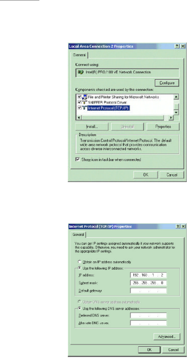
1. Change the TCP/IP setting of your managing computer. Select the TCP/IP line that has been
associated to your network card. Click the Properties button.
2. Make sure the IP address of your computer and the AP are in the same subnet. The default IP
address of the access point is 192.168.1.1 and the default subnet mask is 255.255.255.0.
3
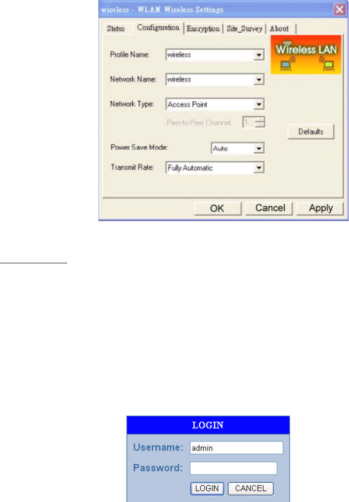
3. For WLAN, open the WLAN client utility. Click Configuration tab. Type default SSID (default
SSID: wireless) in the Network Name field. Choose “Access Point” for Network Type, then
click OK button.
Note: the default channel is 6.Configuring the Router through Web Browser
Chapter 4 Initial Software Installation and Configuration
The access point can be configured through your web browser with the Web-Based Utility.
Open your web browser and type the default IP address of the AP in the address field (default IP:
192.168.1.1) and press Enter. Make sure the IP address of AP and your computer are in the same
subnet.
After the connection is established, you will see the User Login page as shown below. Leave
the password field blank when the first time you open the Web-Based utility. You can change the
password on the “Administrator settings” page.
The system will be time out after idling about 1 minute. You have to login again to re-enter the
main setting page. You can change the idle time out period on the “Administrator settings” page.
On any page, you can click HELP to obtain more descriptions and explanations. To clear any
values you’ve entered on any page, click CANCEL and re-enter information.
4
There are three tabs on the upper right-corner of each page. To go back to the main setting page,
press HOME tab. To log out of the web management, press EXIT tab. To complete any change you
have made, press RESET tab after clicking APPLY button.
5
Chapter 5 Configuring the Access Point through web browser
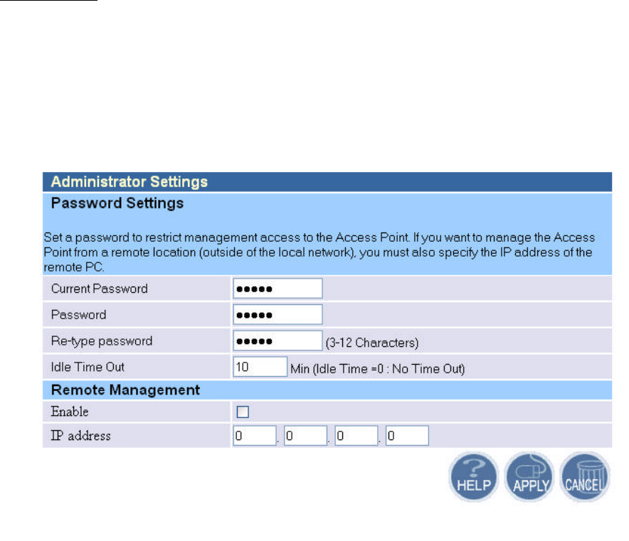
5.1.1 Administrator Settings
Set a password to restrict management access to the access point. If you want to manage the access
point from a remote location (outside of the local network), you must also specify the IP address of
the remote PC.
Password Settings:
To change your password, enter your current password in the “Current Password” box. Enter
new password in the “Password” box. Enter it again in the “Re-type password” box to confirm it.
Click APPLY to complete your change.
The “idle Time Out” is the amount of time of inactivity before the access point will
automatically close the Administrator session. Set this to zero to disable it.
Remote Management:
By default, management access is only available to users on your local network. However, you
can also manage the access point from a remote host. Just check the Enable check box and enter the
IP address of an administrator to this screen.
6
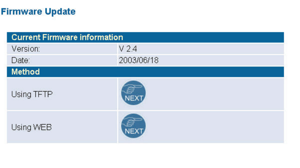
5.1.2 Firmware Upgrade
The firmware information is displayed on this page. You can find firmware version and firmware
date here. There are two ways to upgrade the firmware: “Using TFTP” and “Using WEB”. Click
“NEXT” button to choose the one you want.
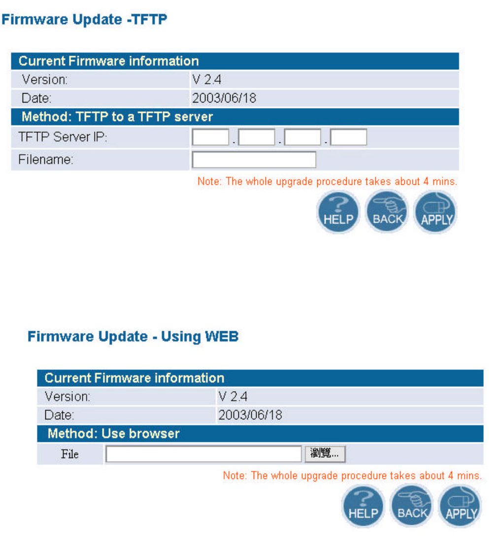
l Using TFTP
On the managed computer, run the TFTP Server utility. And specify the folder in which the
firmware file resides. After running the TFTP server, enter the TFTP server IP and the filename on
the following page. Click on APPLY to complete your change.
7
l Using WEB
Type the correct firmware file path and file name on the File field. You can click Browse to
select the file location. Click on APPLY to complete your change.
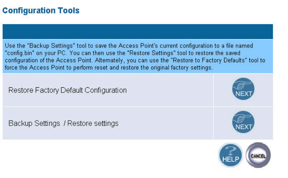
5.1.3 Configuration Tools
This tool can backup or restore the AP’s configuration. It can also restore the original factory
default settings.
l Restore Factory default configuration:
(1) Chick the “Restore Factory Default Configuration” button and then click NEXT.
8
(2) Click Restore button to force the access point to perform reset and restore the original
factory settings.
l Backup Setting/Restore Settings:
(1) Check the “Backup Settings/Restore Settings” radio button and click NEXT.
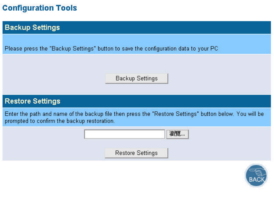
(2) To save the access point's current configuration to a file named "config.bin" on your PC, click
Backup Settings button.
(3) To restore configuration, you can use the "Restore Settings" tool to restore the saved
configuration of the access point.
(4) Enter the path and file name then click Restore Settings button. You can also click Browse to
locate and select the previously saved backup file.
9
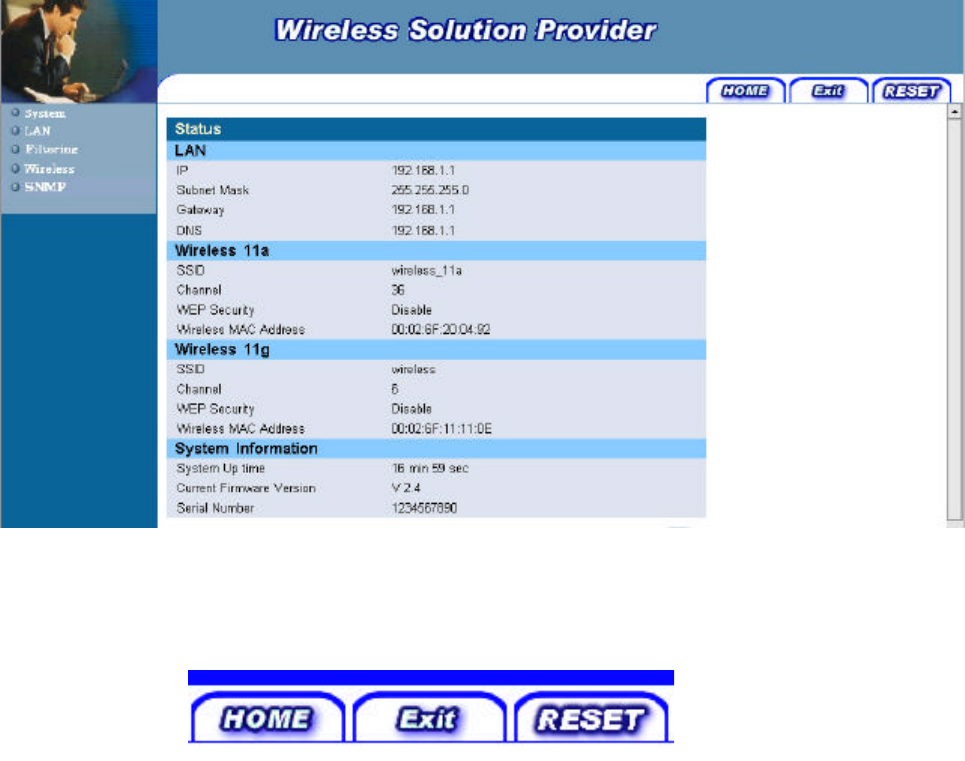
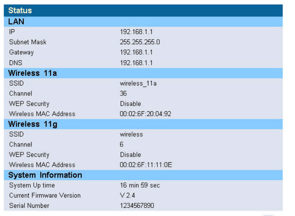
5.1.4 Status
The Status window displays current information and settings for your AP. It has five main
parts – LAN, Wireless 11a, Wireless 11g, System Information.
10
For LAN, it displays AP’s IP address, MAC address, and Subnet Mask. It also displays the IP
address of the DNS and the number of clients connected by DHCP server.
For Wireless 11a, it displays SSID, Channel, WEP security status, and wireless MAC address
of the 11a adapter.
For Wireless 11g, it displays SSID, Channel, WEP security status, and wireless MAC address
of the 11g adapter.
For System Information, it displays system time, firmware version, firmware date, hardware
version, and serial number.
You can obtain the most up-to-date information by pressing the “Refresh” button.
5.1.5 Reset
In the event that the access point stops responding correctly or in some way stops functioning,
you can perform a reset. Your settings will not be changed. To perform the reset, click on the Reset
button below. You will be asked to confirm your decision. The reset will take about 18 seconds.

11
5.2 LAN Setting
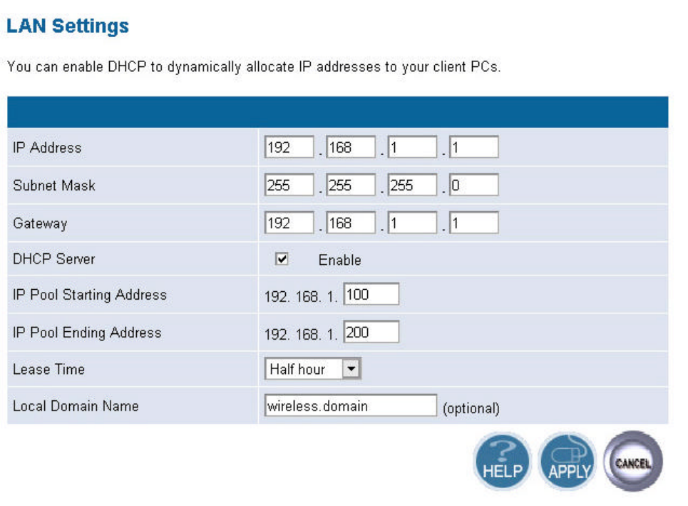
5.2.1 LAN Settings
You can change the basic settings of AP here, including IP address, Subnet mask, IP Pool
Address, Lease Time, and Local Domain Name. Click APPLY to complete your change.
12
(1) IP Address: The IP address of the AP. You should have a unique IP address to your network.
The default value is 192.168.1.1.
(2) Subnet Mask: The Subnet Mask of your access point. The default value is 255.255.255.0.
(3) DHCP Server: By default, the AP can function as a DHCP server. The AP can automatically
assign an IP address to a client. To enable this function, clear the “Enable” check box.
(4) IP Pool Starting Address & IP Pool Ending Address: The first and the last address in the IP
address pool.
(5) Lease Time: The period client can have the IP address assigned by DHCP server.
(6) Local Domain Name: It’s optional.
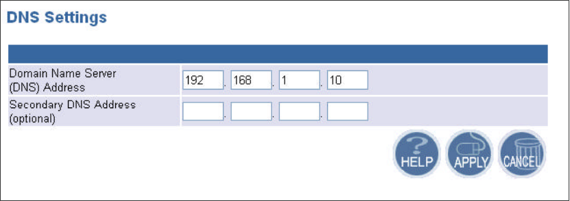
5.2.2 DNS Settings
Domain Name Servers are used to map an IP address to the equivalent domain name. Your ISP
should provide the IP address for one or more domain name servers. The access point can be a DNS
relay to send clients’ request to the Domain Name Server. You can do a DNS lookup to find the IP
address of some specific servers. Click APPLY to complete your change.
13
5.2.3 MAC Control
You can block certain clients PCs accessing the internet based on MAC address.
When you enable “MAC Address Control” without allowing unspecified MAC address
connect to internet, you will block all client PCs accessing the internet. The clients whose MAC
addresses listed in the “MAC Address Control List” can access the internet only if the “Allow
Connect to Internet is checked.
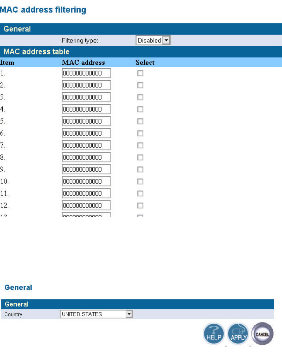
5.2.4 MAC address filtering
The maximum number of items is 64. Check the select check box to include or exclude
corresponding items. The wireless clients whose MAC addresses listed in the “MAC address table”
cannot get associations to the AP while the “Filtering type” is chosen to “Include”. On the other
hand, only those wireless clients’ with MAC addresses listed in the “Exclude” filtering list can
associate to the AP. The MAC address filtering function can be disabled by choosing the “Filtering
type” to “Disable”. Click APPLY to complete your change.
14
5.3 Wireless Setting
General
Select the country regulatory domain which you belong to.
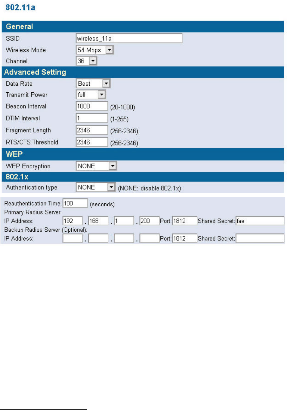
n 11a
In this window you can make changes to the default wireless settings. For communicating, all
computers on the network must be within the same IP Address range, and have the same settings for
the Radio channel and SSID. If you don’t want to utilize WEP Encryption, select “None” to disable
15
this function.
1. SSID: The SSID is a unique name shared among all points in your wireless network. The
SSID must be identical for all points in the network. It is case sensitive and must not exceed
32 characters. The default SSID for 11a Interface is wireless_11a.
2. Channel: The channel shared by all wireless devices. The range of channel is 1~14.
3. WEP: Short for Wired Equivalent Privacy, a security protocol for wireless local area
networks (WLANs) defined in the 802.11a standard. WEP is designed to provide the same
level of security as that of a wired LAN. Select None to disable this function.
There are two WEP Encryption key length: 64-bit(10 hex digits) 128 bit(26 hex digits) and
152 bit(32 hex digits).
n Data Rate: Specify the transmit and receive data rate. Select the desired rate from the
drop-down menu.
n Transmit Power: Specify the level of the transmit power. Use the drop-down menu to
specify the value of the transmit power.
n Beacon Interval (20~1000): Beacon transmissions announce the existence of 802.11
network at regular intervals. Enter a value between 20 and 1000 to specify the Beacon
Interval.
n Data Beacon Rate (1~16384): Specify the Data Beacon Rate. Enter a value between 1
and 16384 that specify the Delivery Traffic Indication Message (DTIM).
n Fragment Length (256~2346): Enter a value between 256 and 3346 to specify the
Fragment Length.
n RTS/CTS Threshold (256~2346): Packets large than the value are preceded by an
RTS/CTS handshake. Enter a value between 256 and 2346 to specify the value of the RTS
/CTS Threshold.
16
4. 802.1X: The 802.1X standard is designed to enhance the security of wireless local area networks
that follow the IEEE 802.11 standard. 802.1X uses an existing protocol, the Extensible
Authentication Protocol (EAP) for message exchange during the authentication process.
In a wireless LAN with 802.1X, a user requests access to an access point (known as the
authenticator). The access point forces the user into an unauthorized state that allows the client to
send only an EAP-start message. The AP replies with an EAP-request identify message to obtain
the clients identity. The clients EAP-response packet containing the clients identity is forwarded to
the authentication server. The authentication server is configured to authenticate clients with a
specific authentication algorithm. The result is an accept or reject packet from authentication server
to AP. Once authenticated, the AP opens the client’s port and traffic will be forwarded.
Authentication type: There are three EAP (Extensible Authentication Protocol) types supported.
You can choose between EAP-TLS1, EAP-MD52, and EAP -TTLS3. You can choose NONE to
disable the 802.1X.
1 TLS- Transport Layer Security (TLS) is a protocol that ensures privacy between communicating applications and their users on the

17
Re-authentication time: The time period that AP informs clients to re-authenticate.
Radius Server:
1. Primary Radius Server: The IP address and port number of Primary Radius Server. You
need to know the shared secret between AP and Radius Server. The default port number is 1812.
2. Backup Radius Server: The IP address, shared secret, and port number of backup Radius
Server. It is optional.
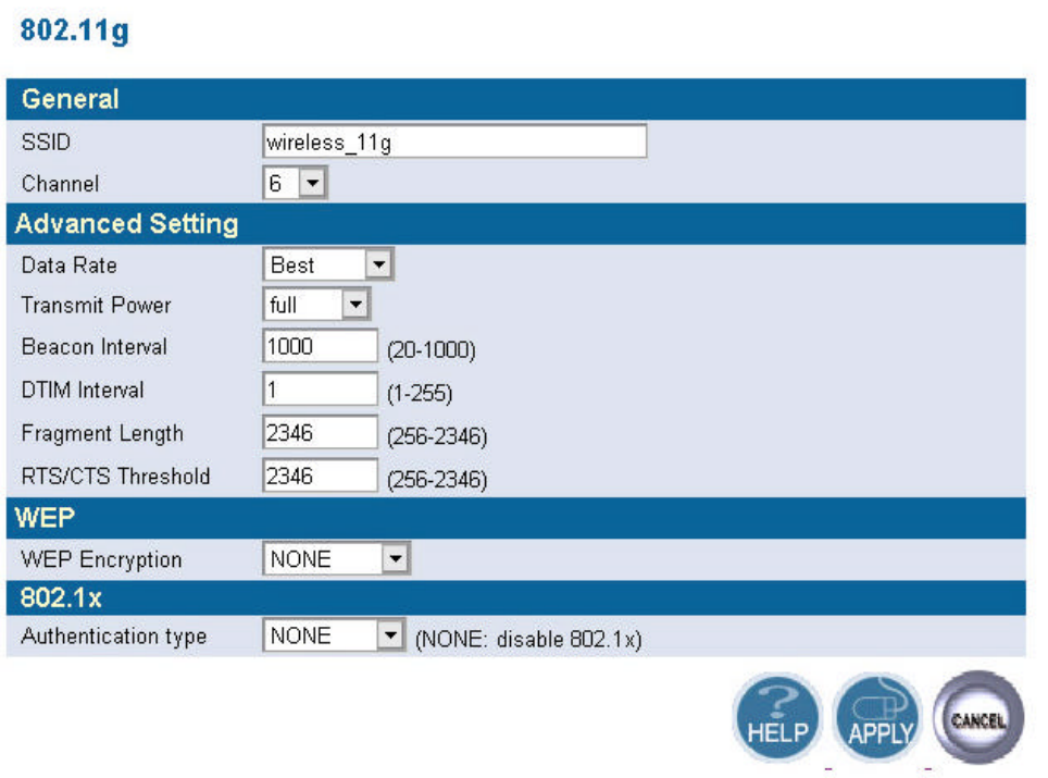
n 11g
In this window you can make changes to the default wireless settings. For communicating, all
computers on the network must be within the same IP Address range, and have the same settings for
the Radio channel and SSID. If you don’t want to utilize WEP Encryption, select “None” to disable
this function.
1. SSID: The SSID is a unique name shared among all points in your wireless network. The
SSID must be identical for all points in the network. It is case sensitive and must not
exceed 32 characters. The default SSID for 11g Interface is wireless_11g.
2. Channel: The channel shared by all wireless devices. The range of channel is 1~14.
3. WEP: Short for Wired Equivalent Privacy, a security protocol for wireless local area
networks (WLANs) defined in the 802.11a standard. WEP is designed to provide the same
level of security as that of a wired LAN. Select None to disable this function.
There are two WEP Encryption key length: 64-bit(10 hex digits) 128 bit(26 hex digits) and
152 bit(32 hex digits).
n Data Rate: Specify the transmit and receive data rate. Select the desired rate from the
drop-down menu.
n Transmit Power: Specify the level of the transmit power. Use the drop-down menu to
specify the value of the transmit power.
n Beacon Interval (20~1000): Beacon transmissions announce the existence of 802.11
network at regular intervals. Enter a value between 20 and 1000 to specify the Beacon
Interval.
n Data Beacon Rate (1~16384): Specify the Data Beacon Rate. Enter a value between 1
and 16384 that specify the Delivery Traffic Indication Message (DTIM).
n Fragment Length (256~2346): Enter a value between 256 and 3346 to specify the
Fragment Length.
Internet. When a server and client communicate, TLS ensures that no third party may eavesdrop or tamper with any message. TLS is the
successor to the Secure Sockets Layer.
2 MD5- provides basic security and is analogous to the challenge handshake authentication protocol (CHAP). MD5 is intended for use
with signal signature applications, which require that large files must be compressed by a secure method before being encrypted with a
secret key, under a public key cryptosystem.
3 TTLS- provides mutual authentication, supports legacy password protocols and does not require clients to have certificates. As a result,
enterprises can reduce the costs associated with operating a certificate authority to distribute and revoke user certificates.
18
n RTS/CTS Threshold (256~2346): Packets large than the value are preceded by an
RTS/CTS handshake. Enter a value between 256 and 2346 to specify the value of the RTS
/CTS Threshold.
4. 802.1X: The 802.1X standard is designed to enhance the security of wireless local area
networks that follow the IEEE 802.11 standard. 802.1X uses an existing protocol, the
Extensible Authentication Protocol (EAP) for message exchange during the authentication
process.
In a wireless LAN with 802.1X, a user requests access to an access point (known as the
authenticator). The access point forces the user into an unauthorized state that allows the
client to send only an EAP-start message. The AP replies with an EAP-request identify
message to obtain the clients identity. The clients EAP-response packet containing the
clients identity is forwarded to the authentication server. The authentication server is
configured to authenticate clients with a specific authentication algorithm. The result is an
accept or reject packet from authentication server to AP. Once authenticated, the AP opens
the client’s port and traffic will be forwarded.

19
Authentication type: There are three EAP (Extensible Authentication Protocol) types
supported. You can choose between EAP-TLS4, EAP-MD55, and EAP -TTLS6. You can
choose NONE to disable the 802.1X.
Re-authentication time: The time period that AP informs clients to re-authenticate.
Radius Server:
1. Primary Radius Server: The IP address and port number of Primary Radius Server.
You need to know the shared secret between AP and Radius Server. The default port number
is 1812.
2. Backup Radius Server: The IP address, shared secret, and port number of backup
Radius Server. It is optional.
4 TLS- Transport Layer Security (TLS) is a protocol that ensures privacy between communicating applications and their users on the
Internet. When a server and client communicate, TLS ensures that no third party may eavesdrop or tamper with any message. TLS is the
successor to the Secure Sockets Layer.
5 MD5- provides basic security and is analogous to the challenge handshake authentication protocol (CHAP). MD5 is intended for use
with signal signature applications, which require that large files must be compressed by a secure method before being encrypted with a
secret key, under a public key cryptosystem.
6 TTLS- provides mutual authentication, supports legacy password protocols and does not require clients to have certificates. As a result,
enterprises can reduce the costs associated with operating a certificate authority to distribute and revoke user certificates.
20
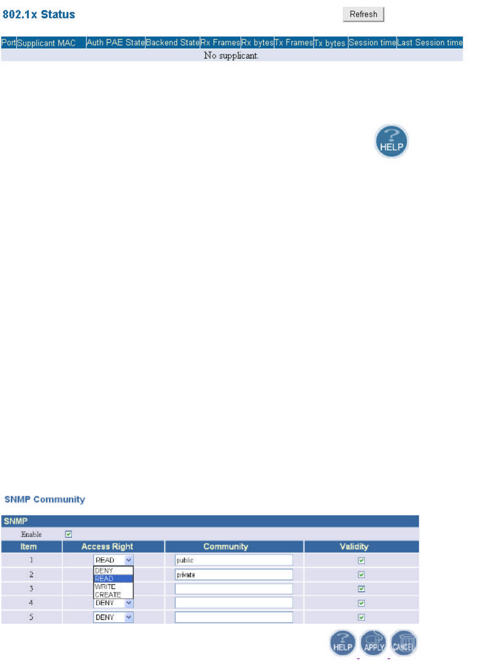
n 802.1x Status
In this window, it shows the 802.1x status information of the supplicants, including the
port number, MAC address, Authentication PAE state, Backend state, Rx bytes, Tx
Frames, Tx bytes, Session time, and Last Session time.
5.4 SNMP
Short for Simple Network Management Protocol, a set of protocols for managing complex
networks. SNMP works by sending messages, called protocol data units (PDUs), to different parts
of a network. SNMP-compliant devices, called agents, store data about themselves in Management
Information Bases (MIBs) and return this data to the SNMP requesters.
5.4.1 SNMP Community
SNMP Community provides a simple kind of password protection. Access to the SNMP
device is controlled through community names. The community name can be thought of as a
password. If you don’t have the correct community name you can’t retrieve any data (get) or make
any changes (sets). Multiple SNMP managers may be organized in a specified community. You can
change your SNMP community settings on this screen. Check the “Enable” check box to enable the
SNMP function. Click APPLY to complete your change.
Validity: You can enable or disable the SNMP function of the corresponding community item.
21
Access Right: Select a access right for the corresponding SNMP community
(Deny7/Read8/Write9).
Community: Specify the name of community for the SNMP manager( Private/Public). By
convention, “Public” community is with a read-only access right.
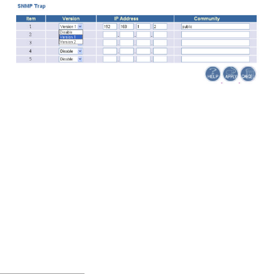
5.4.2 SNMP Trap
Traps can be used by network entities to signal abnormal conditions to management stations.
SNMP TRAP message can be sent to a host. Click APPLY to complete your settings.
Version: Select the SNMP Version.
Select “Disable” to disable the snmp trap function of the corresponding item.
Version1: SNMP Version1
Version2: SNMP Version2
IP Address: Specify the IP Address of the SNMP Manager for SNMP Trap Report.
Community: Specify the name of community ( public/Private) for SNMP manager.
Following are the traps supported in the access point:
Cold-start trap:
This trap indicates that the specified node’s power has just come on. The cold-start trap is
generated every time the access point is power-cycled. Cold-start traps are not generated
until three seconds after the access point is power-cycled. This allows time for the hardware
providing the low-level IP network interface to start up and stabilize before attempting to
send a packet.
7 Deny community will not allow a remote device to read information from a device or to modify settings on that
device.
8 Read-only community enables a remote device to retrieve "read-only" information from a device.
9 Read-Write community allows a remote device to read information from a device and to modify settings on that
device.
22
Federal Communication Commission Interference Statement
This equipment has been tested and found to comply with the limits for a Class B
digital device, pursuant to Part 15 of the FCC Rules. These limits are designed to
provide reasonable protection against harmful interference in a residential
installation. This equipment generates, uses and can radiate radio frequency
energy and, if not installed and used in accordance with the instructions, may cause
harmful interference to radio communications. However, there is no guarantee that
interference will not occur in a particular installation. If this equipment does cause
harmful interference to radio or television reception, which can be determined by
turning the equipment off and on, the user is encouraged to try to correct the
interference by one of the following measures:
-Reorient or relocate the receiving antenna.
-Increase the separation between the equipment and receiver.
-Connect the equipment into an outlet on a circuit different from that
to which the receiver is connected.
-Consult the dealer or an experienced radio/TV technician for help.
This device complies with Part 15 of the FCC Rules. Operation is subject to the
following two conditions: (1) This device may not cause harmful interference, and (2)
this device must accept any interference received, including interference that may
cause undesired operation.
FCC Caution: Any changes or modifications not expressly approved by the party
responsible for compliance could void the user's authority to operate this equipment.
IMPORTANT NOTE:
FCC Radiation Exposure Statement:
This equipment complies with FCC radiation exposure limits set forth for an
uncontrolled environment. This equipment should be installed and operated with
minimum distance 20cm between the radiator & your body.
If this device is going to be operated in 5.15 ~ 5.25GHz frequency range, then it is
restricted in indoor environment only.
This transmitter must not be co-located or operating in conjunction with any other
antenna or transmitter.