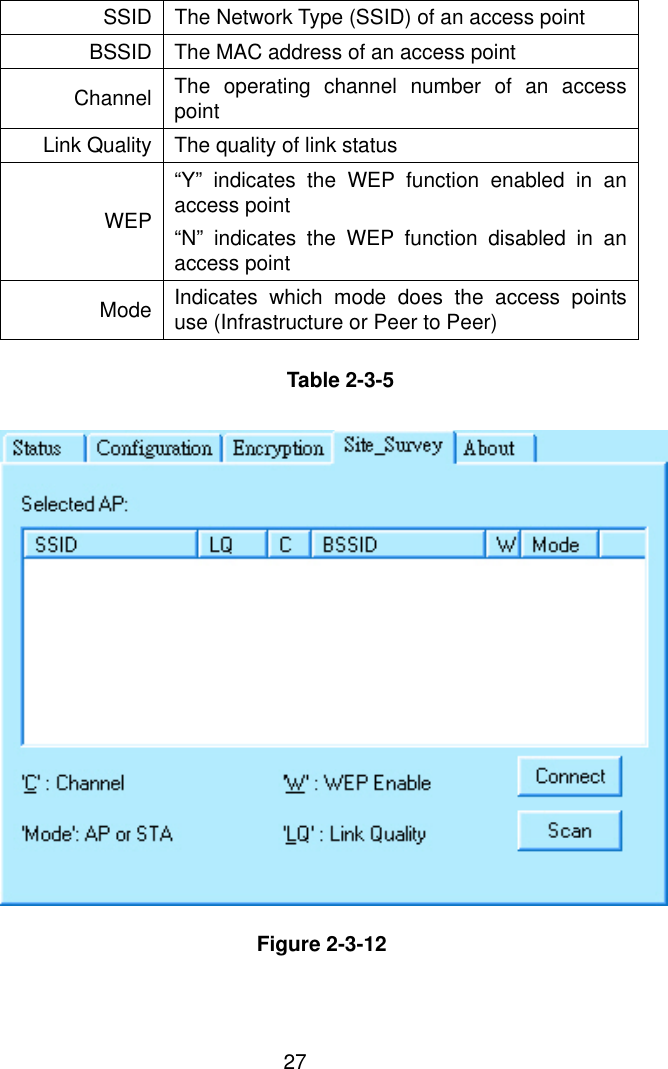
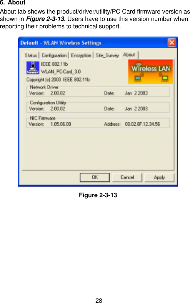
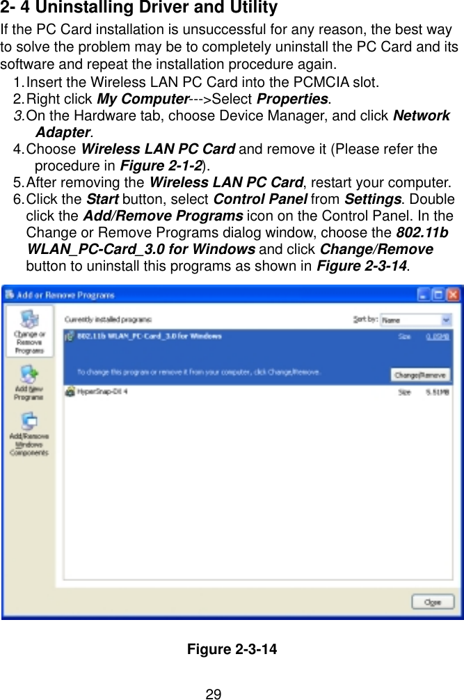
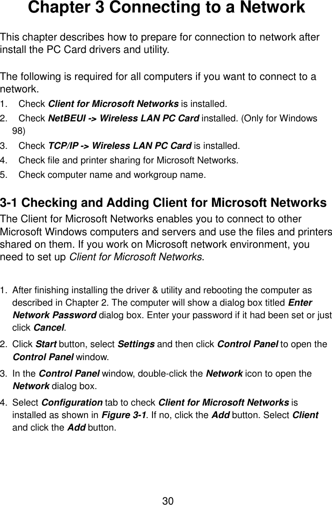
Senao Co IS20V311-PLUS Long Range Wireless PCMCIA Card User Manual Manual
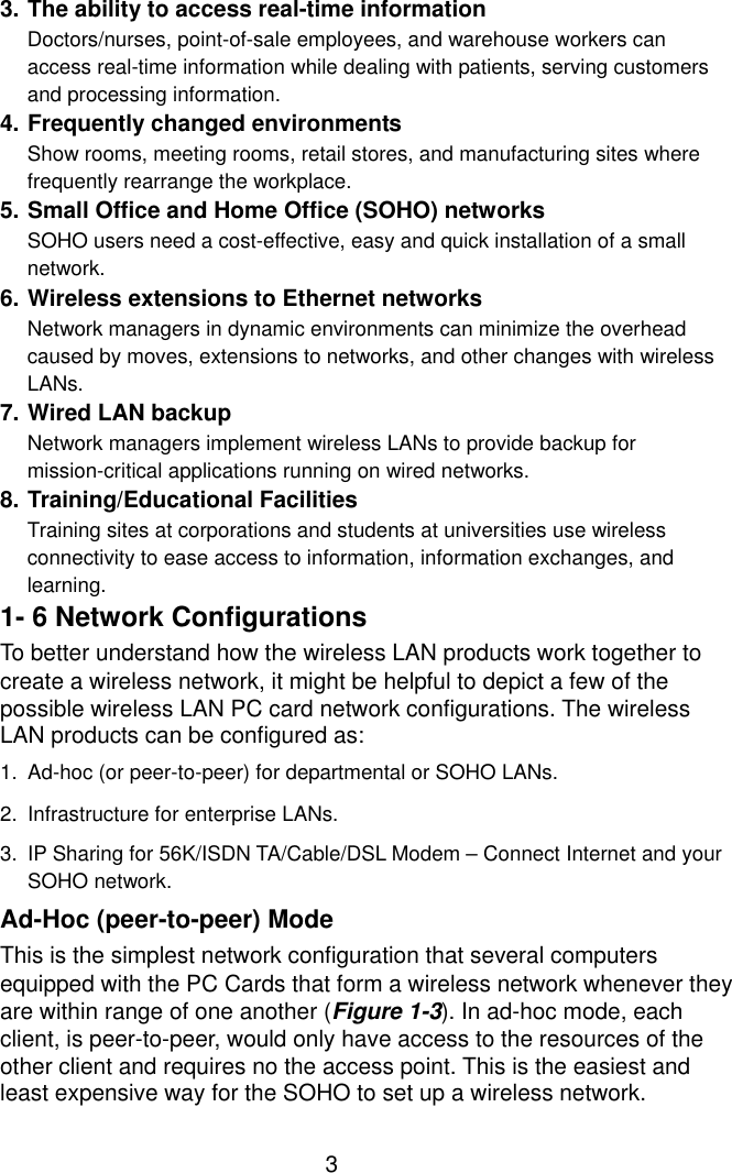
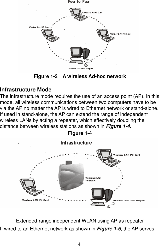
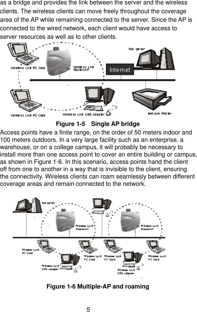
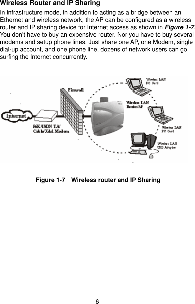
Senao International Co Ltd Long Range Wireless PCMCIA Card Manual
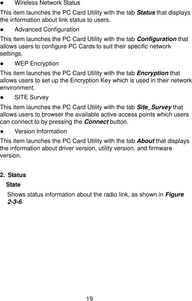
UserManual.wiki
>
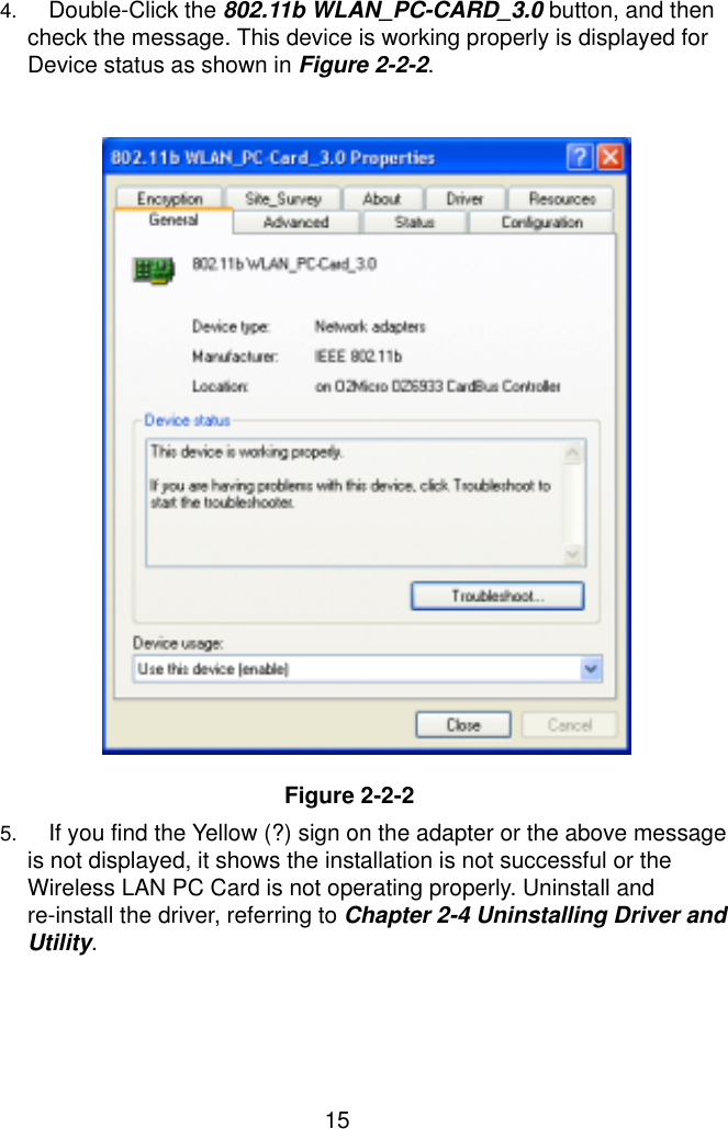
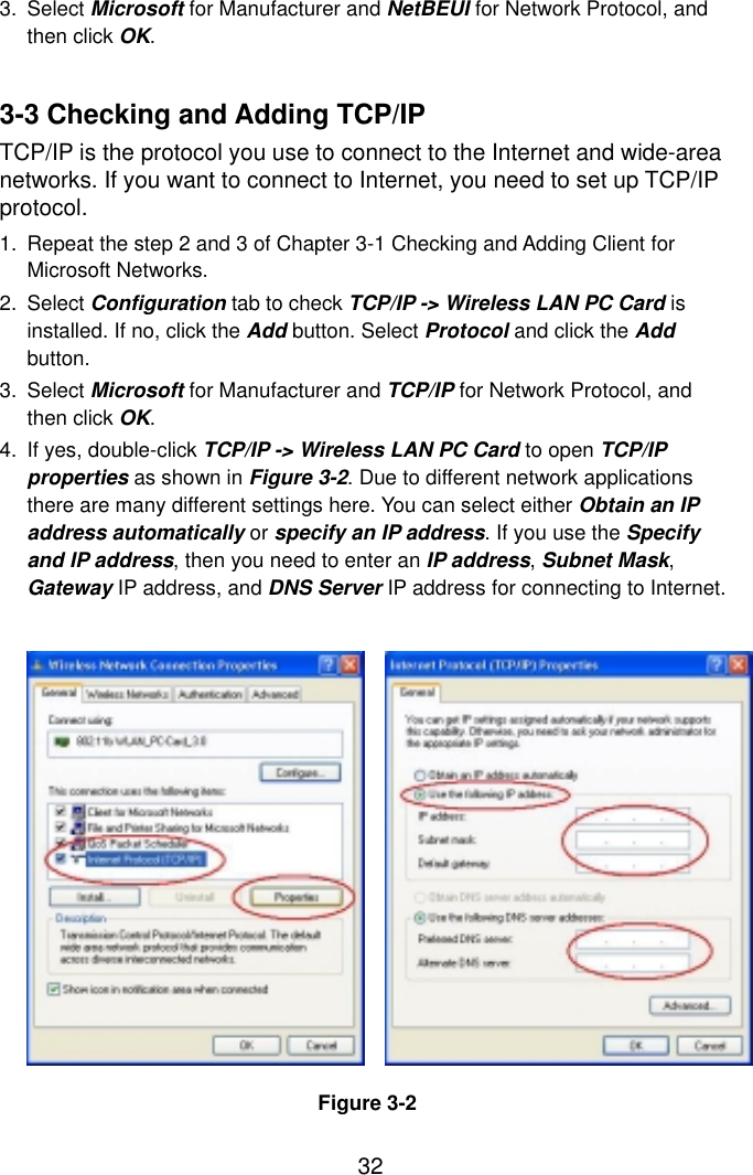
Senao Co
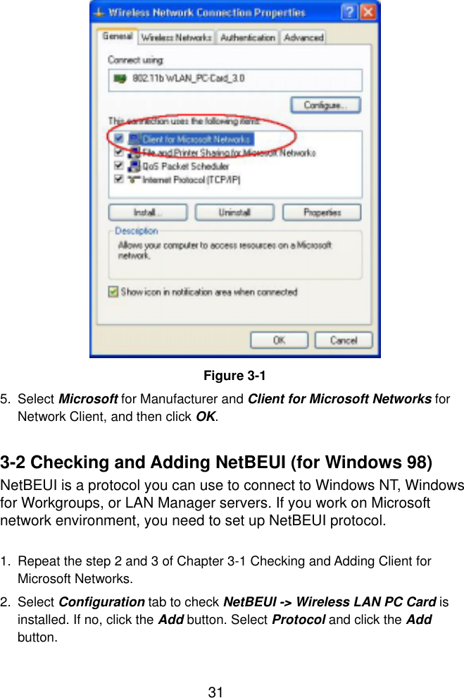
>
IS20V311 PLUS User Manual
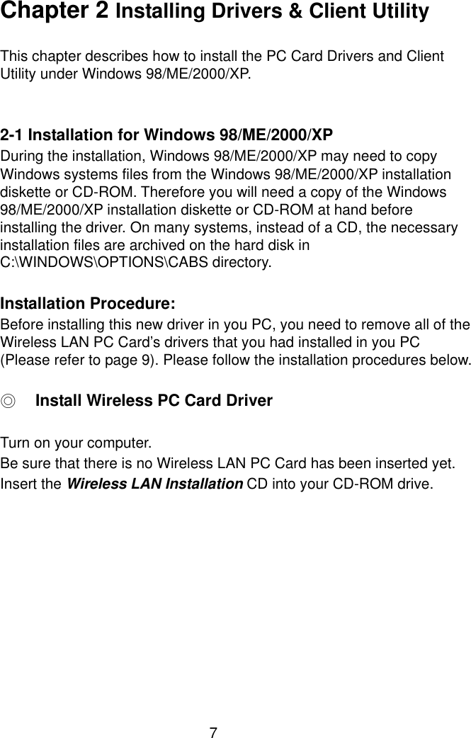
Manual
Navigation menu
Upload a User Manual
Namespaces
Wiki Guide
HTML
PDF
Info
Views
User Manual
Discussion / Help
Navigation