Senao Co RL30V114 Wireless 11g Cardbus Adapter User Manual WPC 3006 UsersManual V10
Senao International Co Ltd Wireless 11g Cardbus Adapter WPC 3006 UsersManual V10
UserManual.wiki
>
Senao Co
>
RL30V114 User Manual
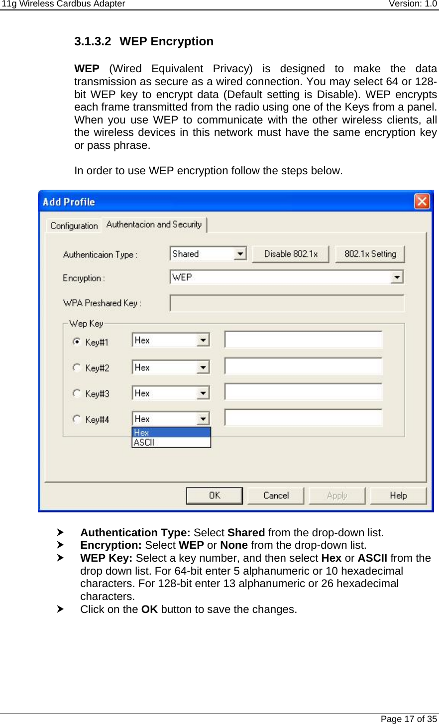
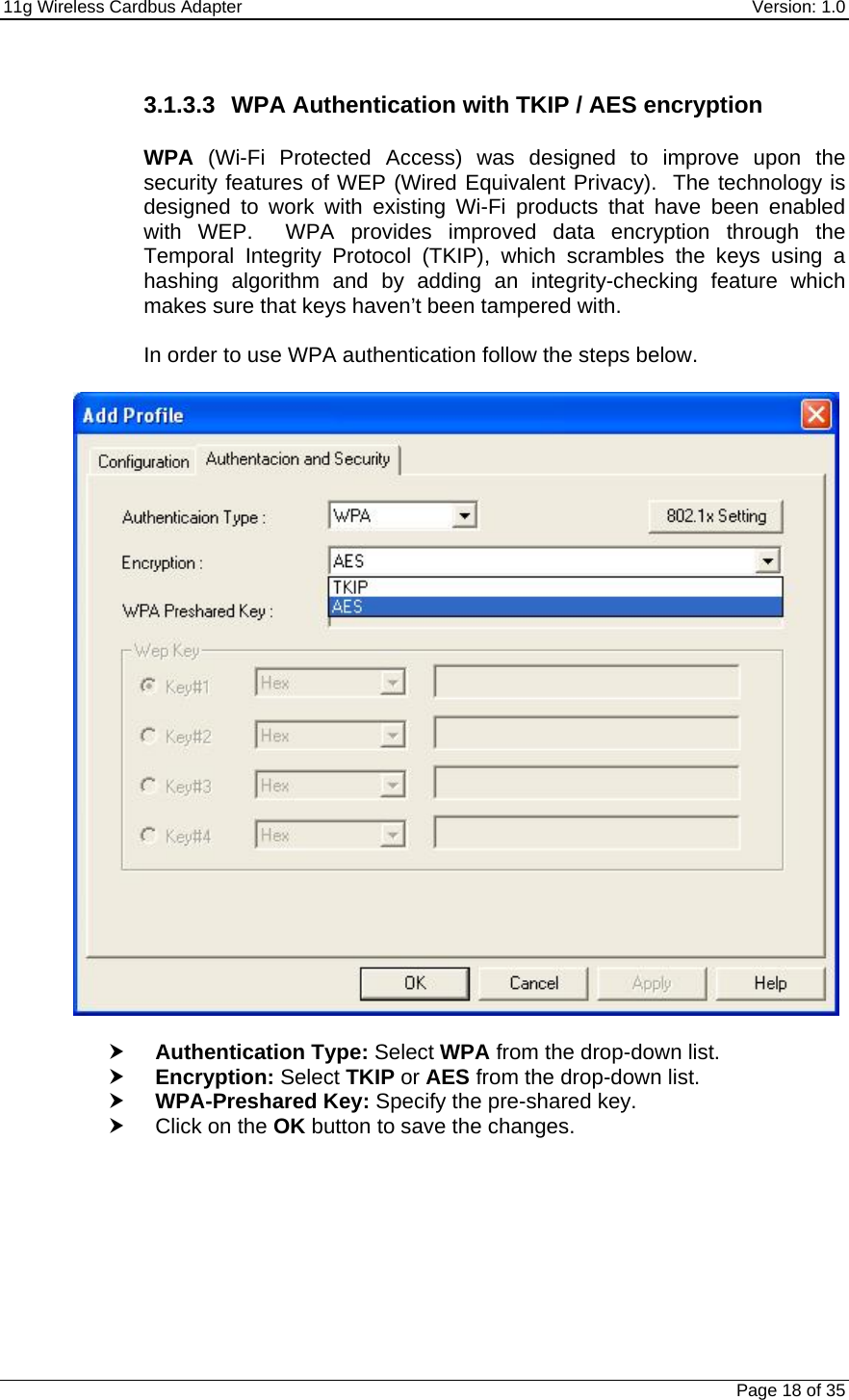
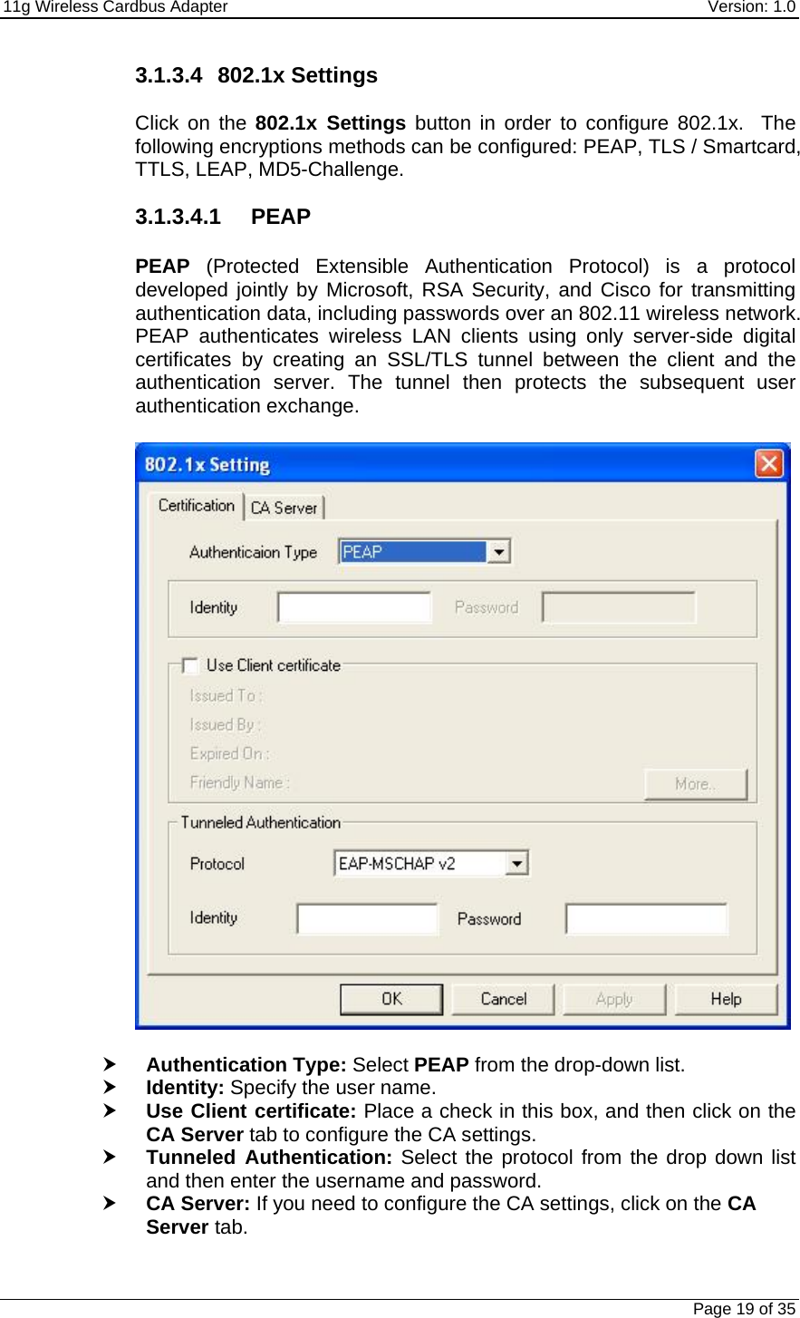
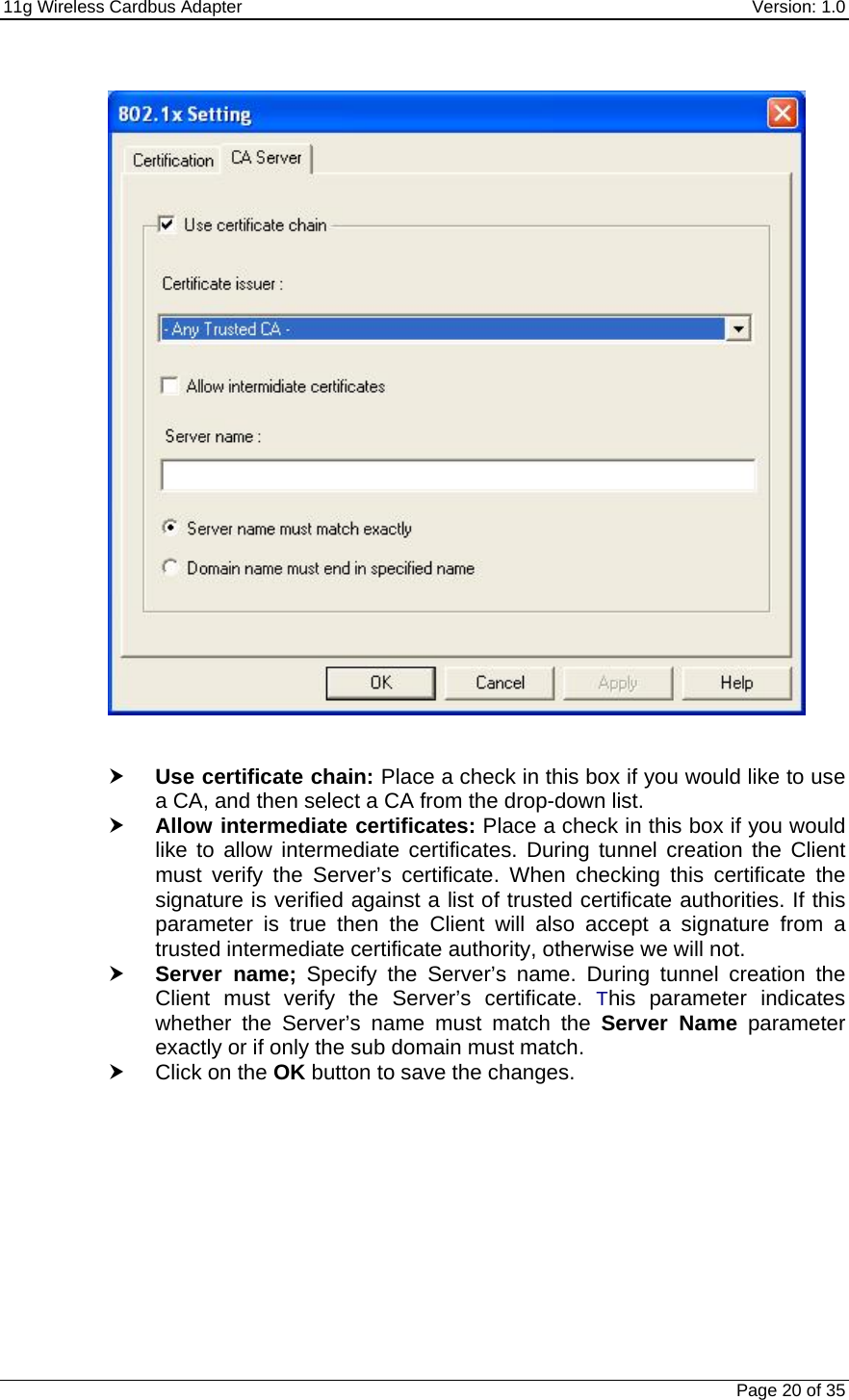
Users manual
Navigation menu
Upload a User Manual
Namespaces
Wiki Guide
HTML
PDF
Info
Views
User Manual
Discussion / Help
Navigation