Senao Co SL-2011CD-ANT Wireless LAN Card User Manual 2nd Revised Users Manual
Senao International Co Ltd Wireless LAN Card 2nd Revised Users Manual
Senao Co >
Contents
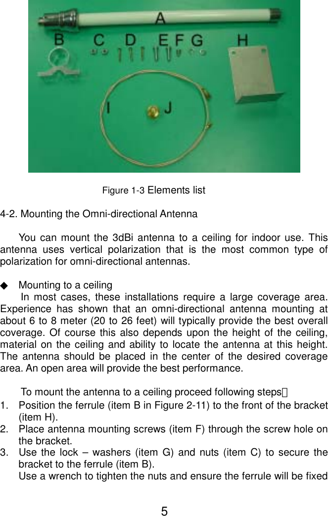
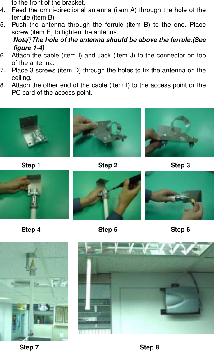
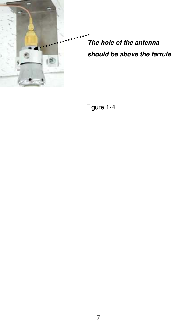
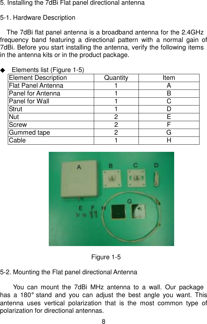
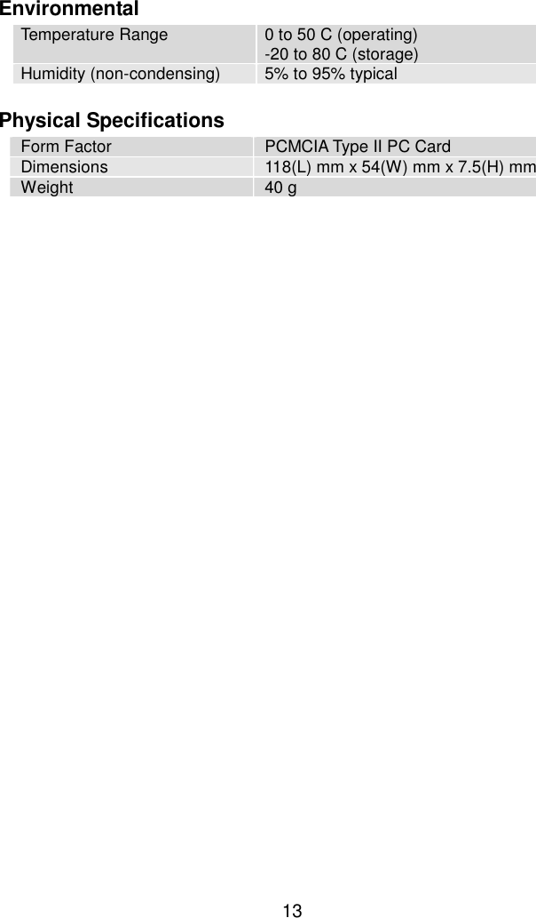
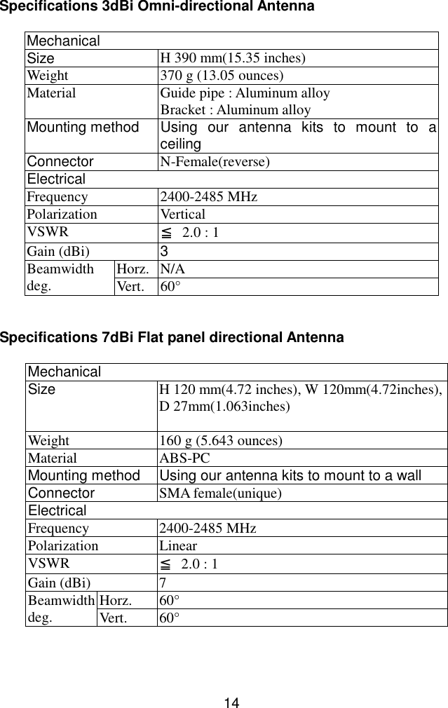
- 1. 2nd Revised Users Manual
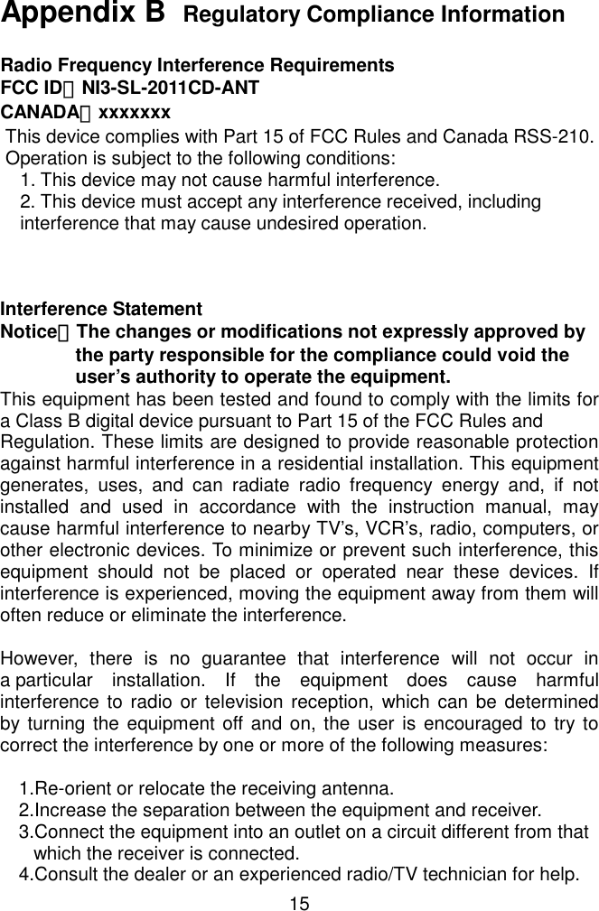
- 2. DoC Statement
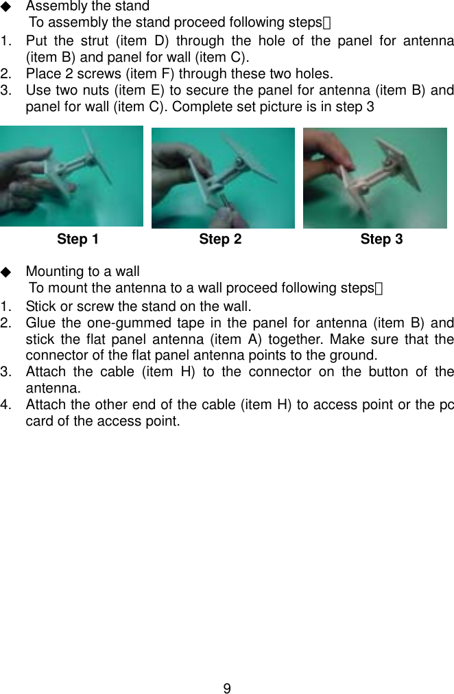
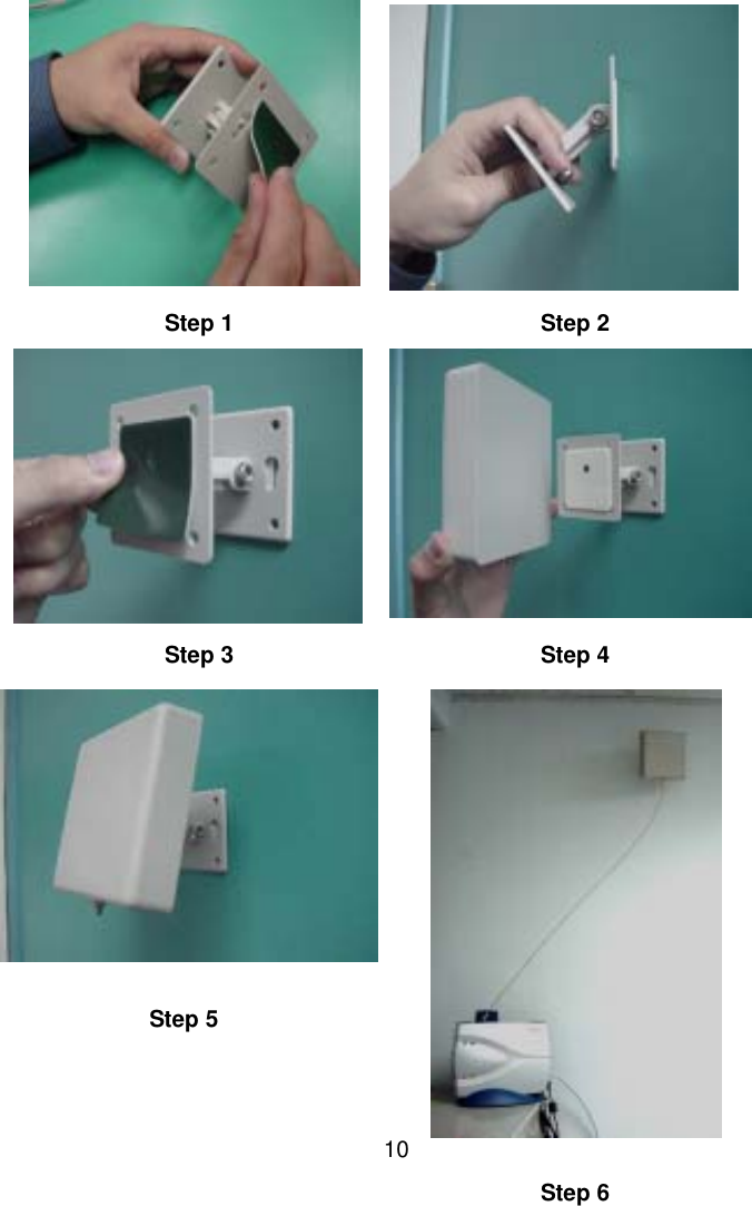
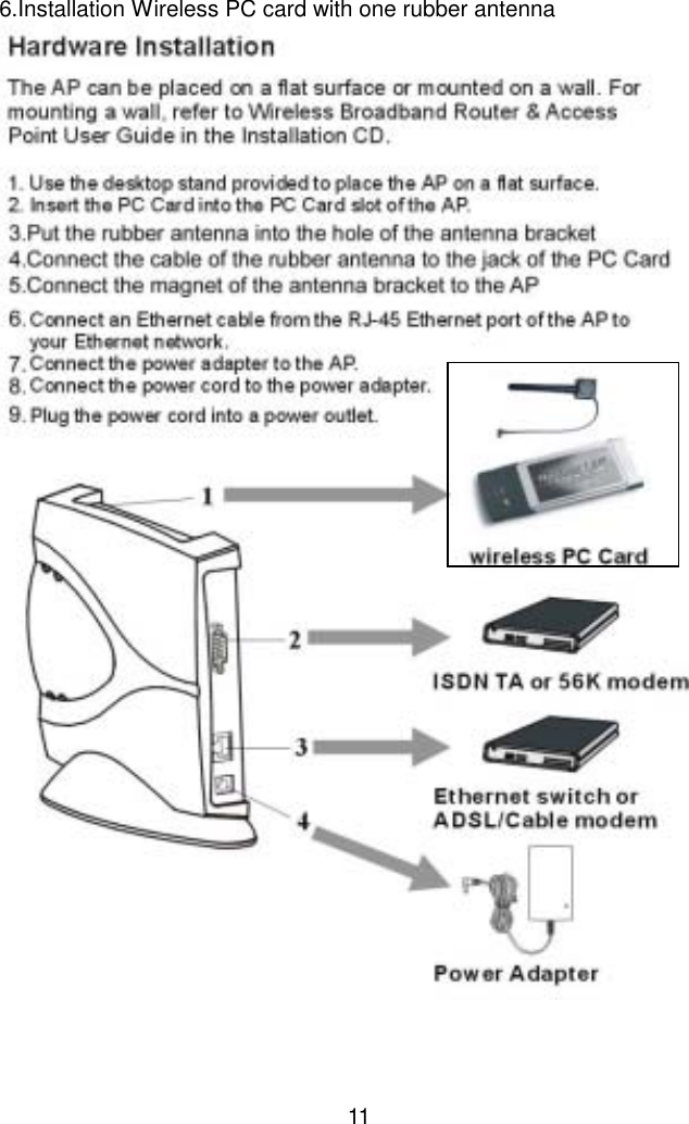
2nd Revised Users Manual