Senao Networks AN300APIN Araknis Networks 300-series Dual-Band Concurrent Wireless-N Indoor Access Point User Manual
Senao Networks, Inc. Araknis Networks 300-series Dual-Band Concurrent Wireless-N Indoor Access Point
Contents
- 1. User Manual (Statement).pdf
- 2. User Manual.pdf
User Manual.pdf
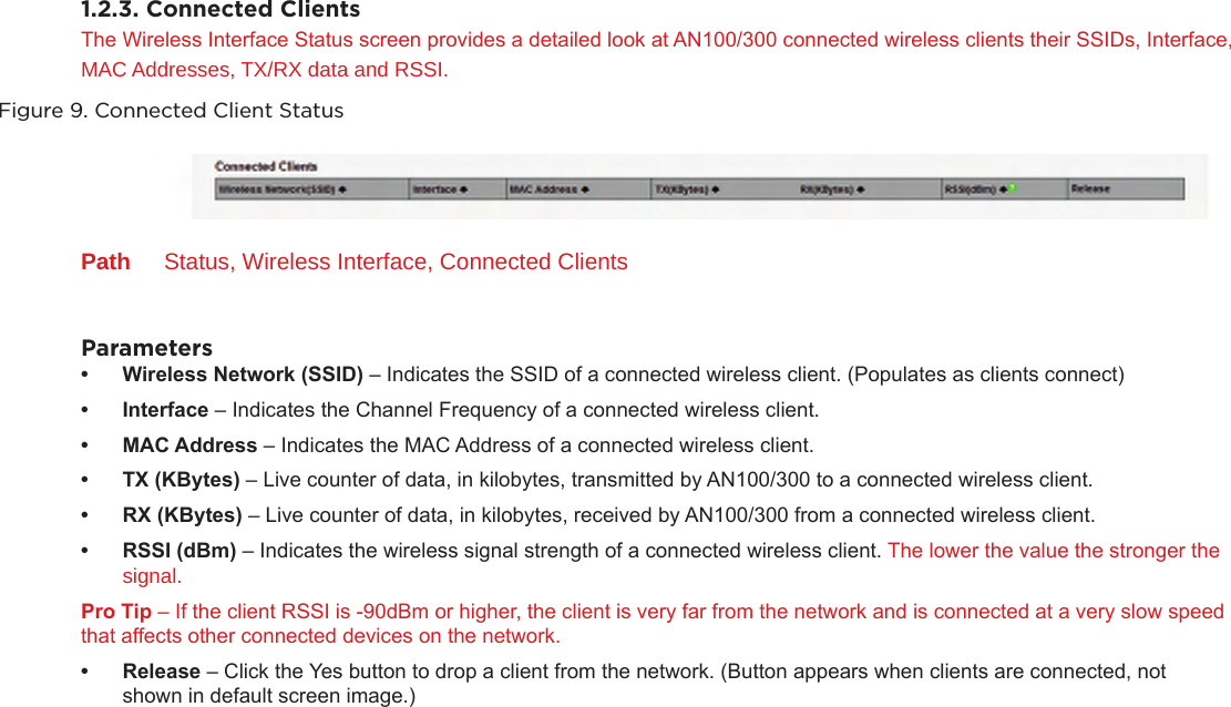
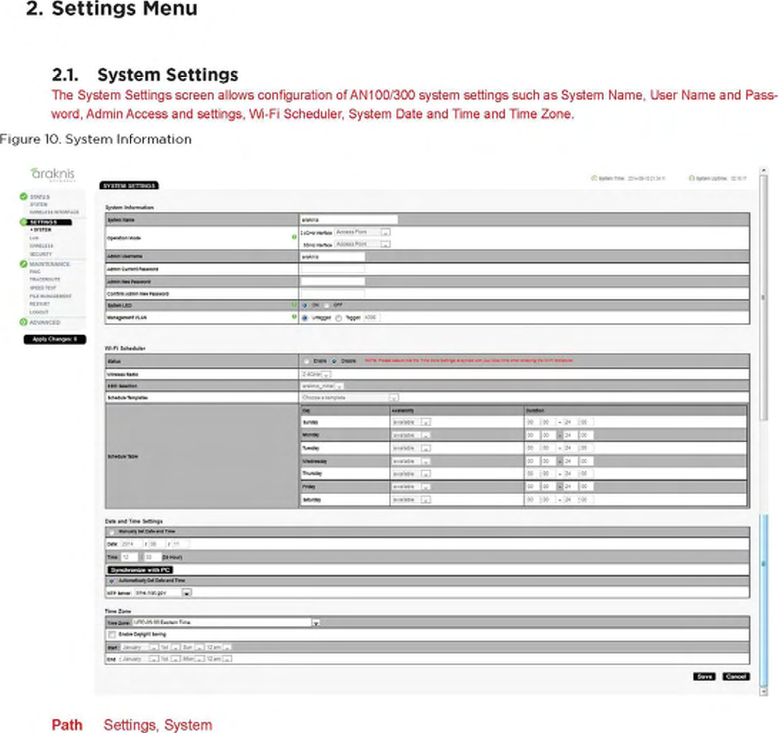
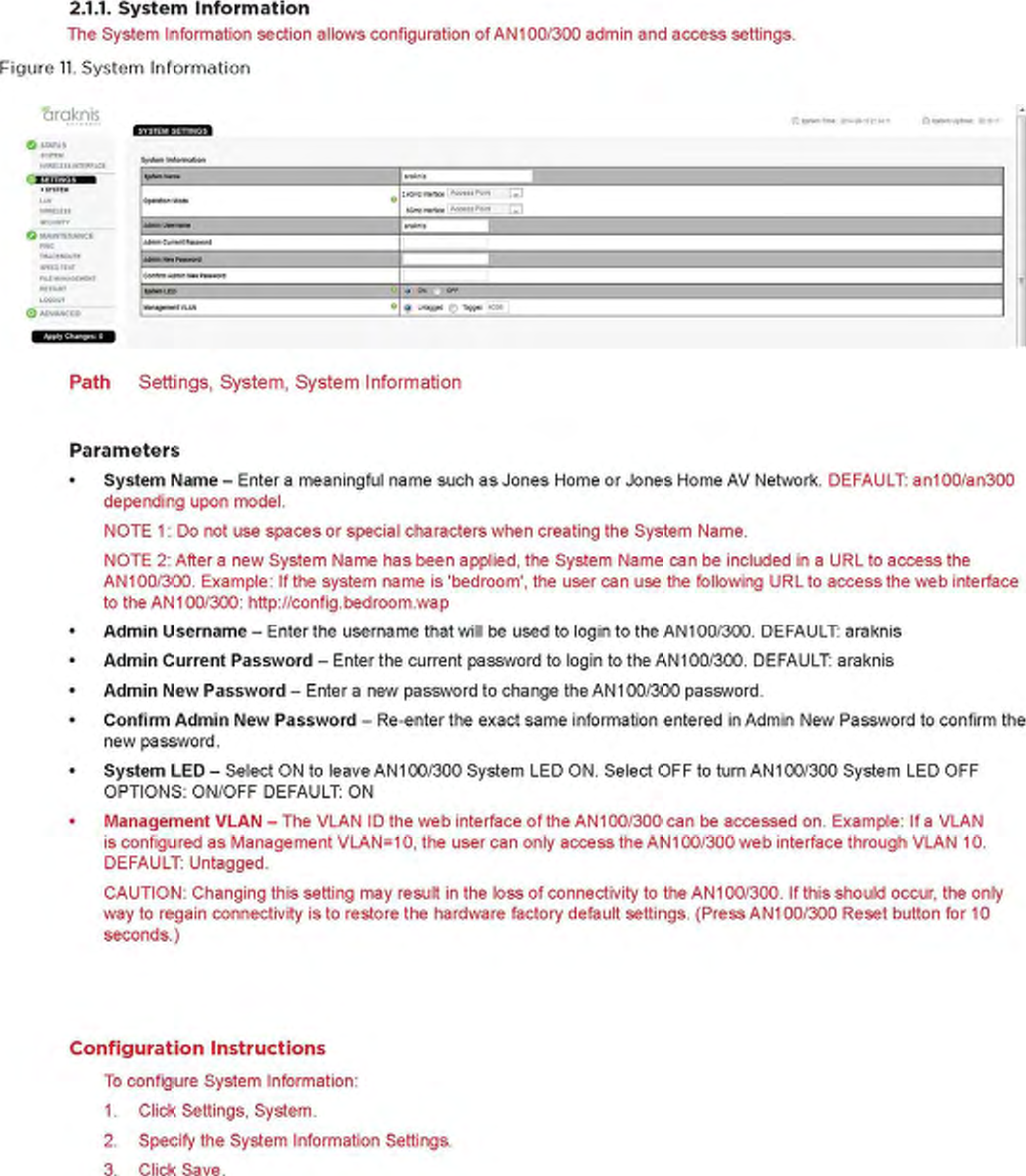
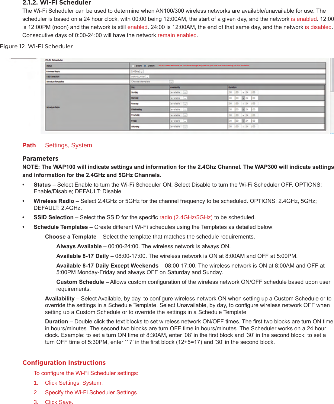
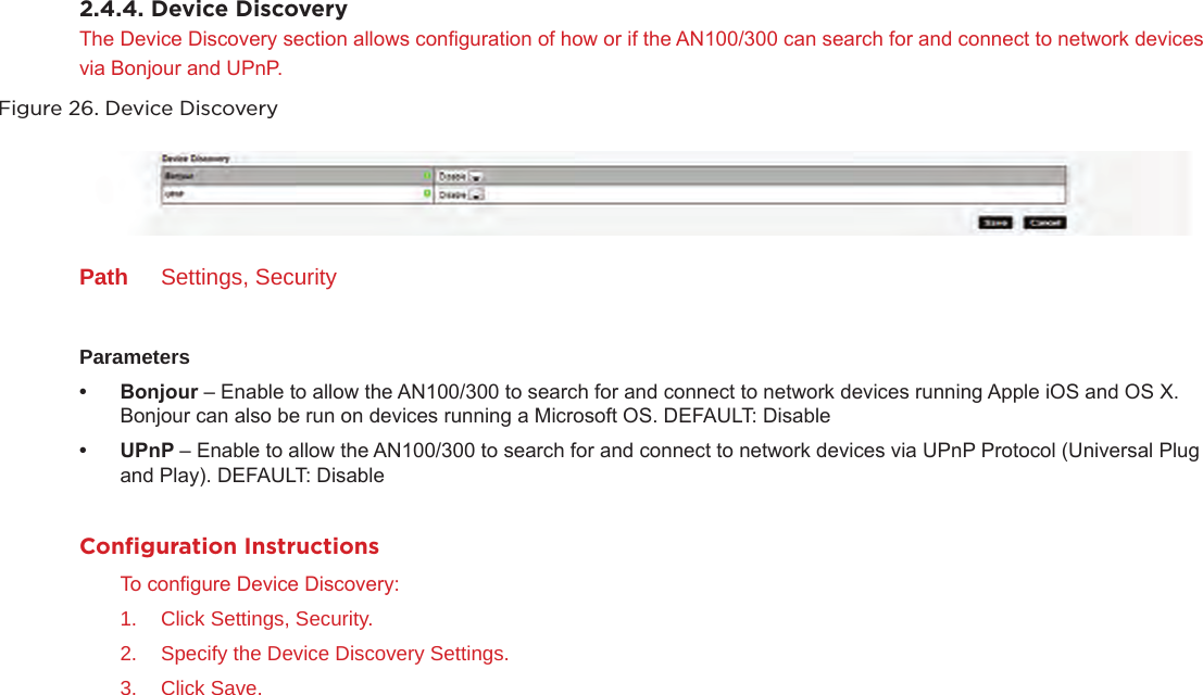
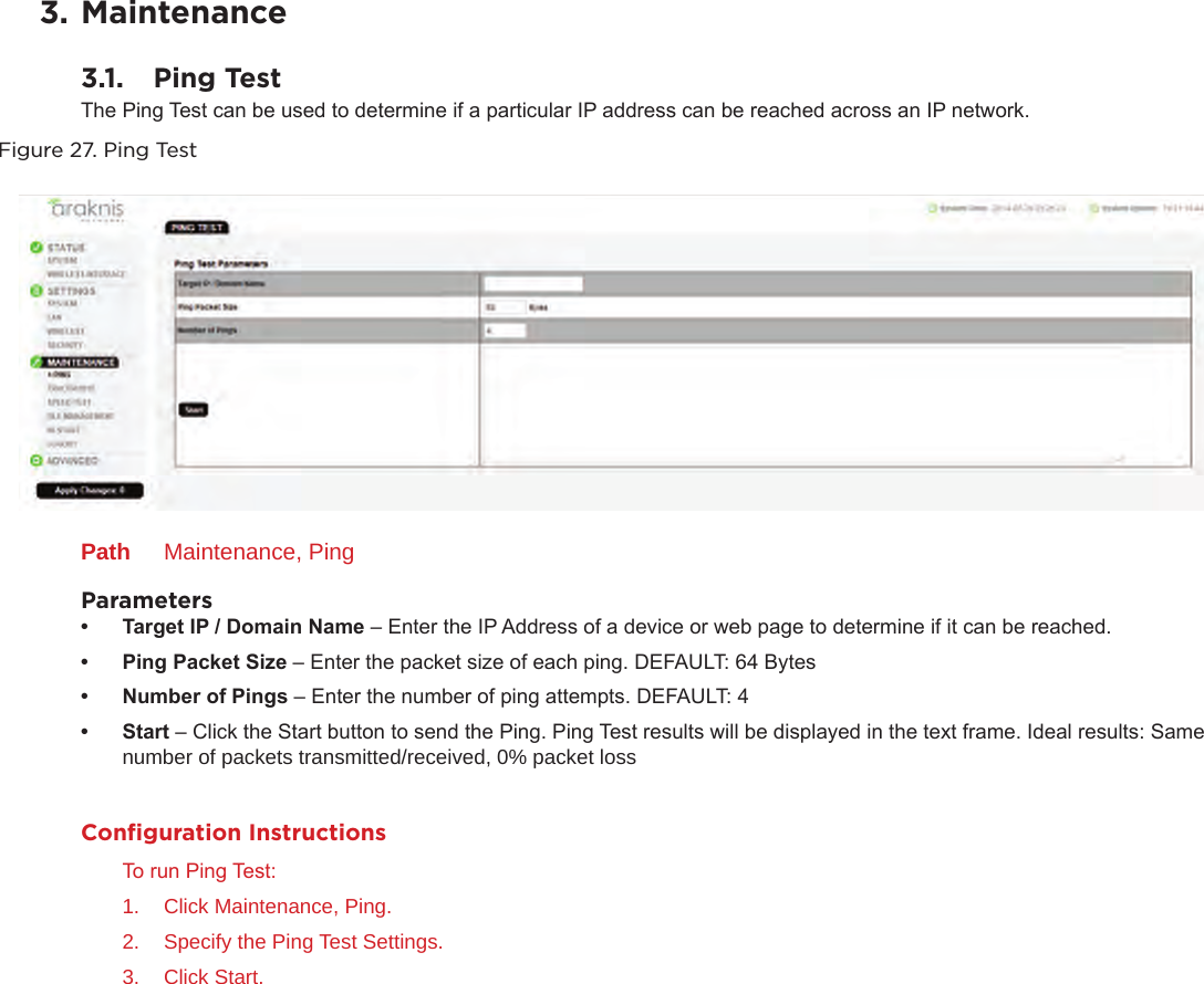
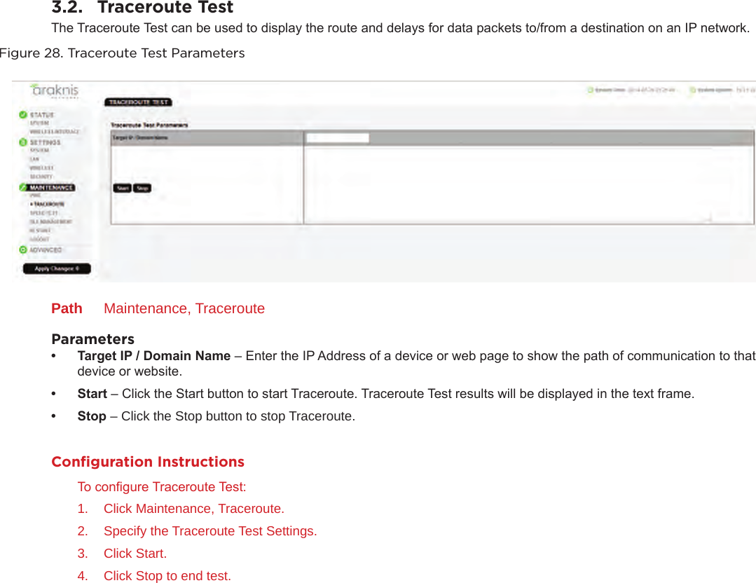
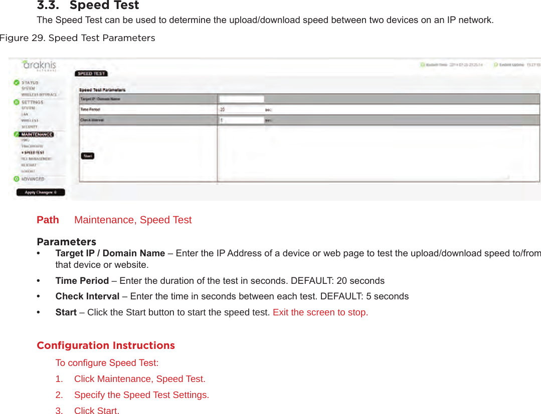
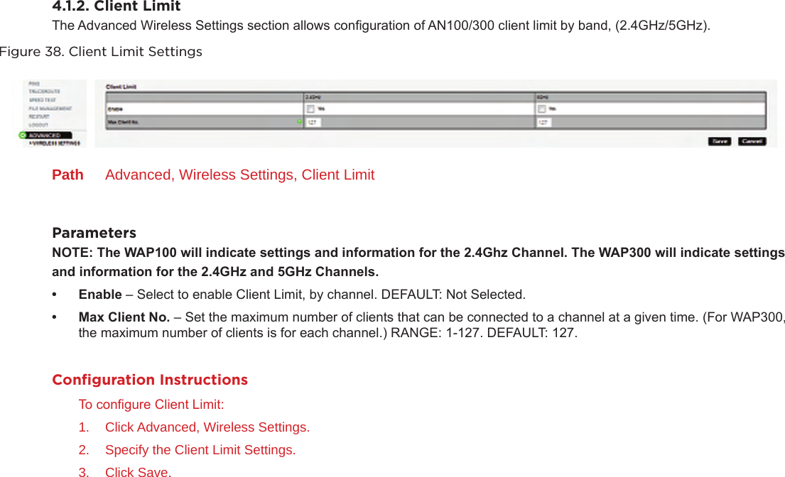
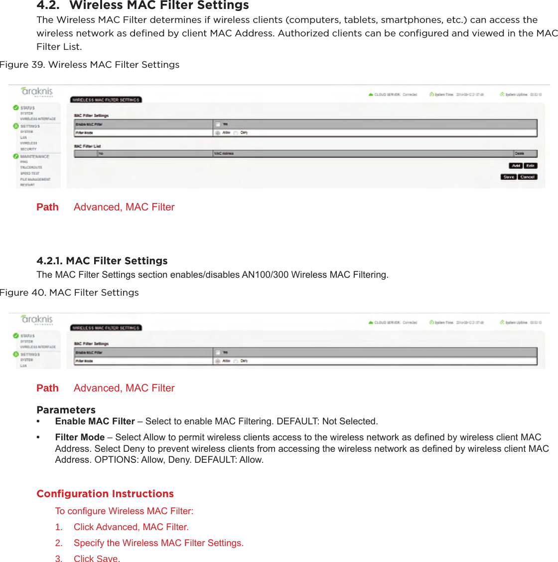
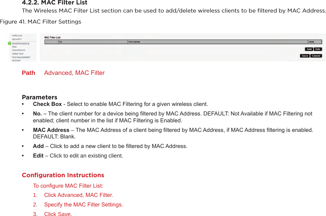
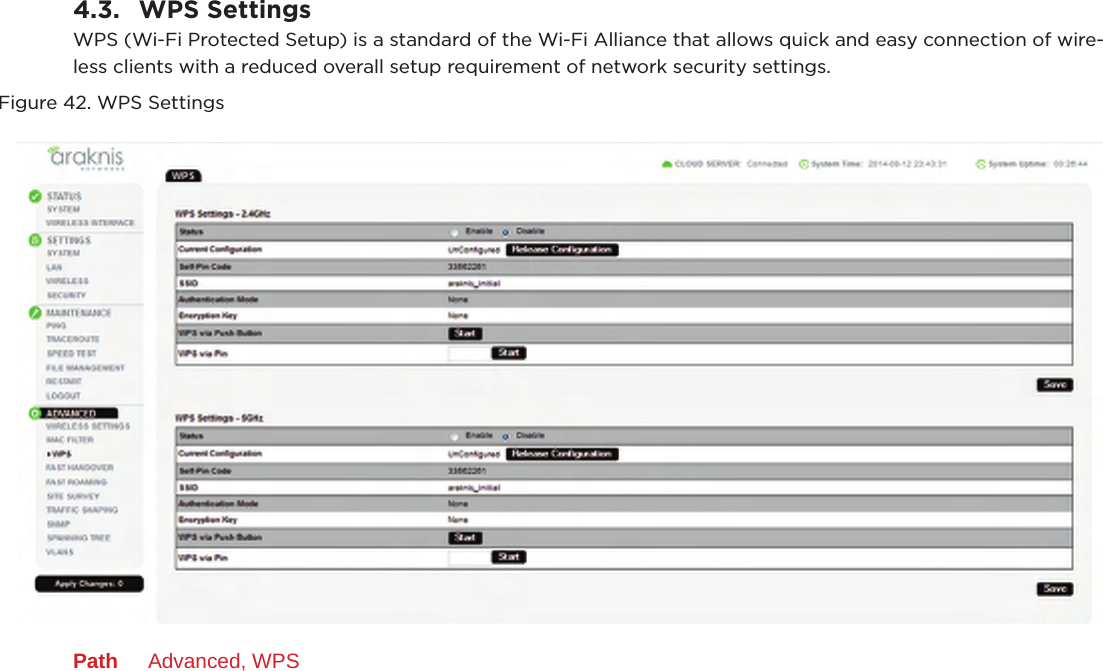
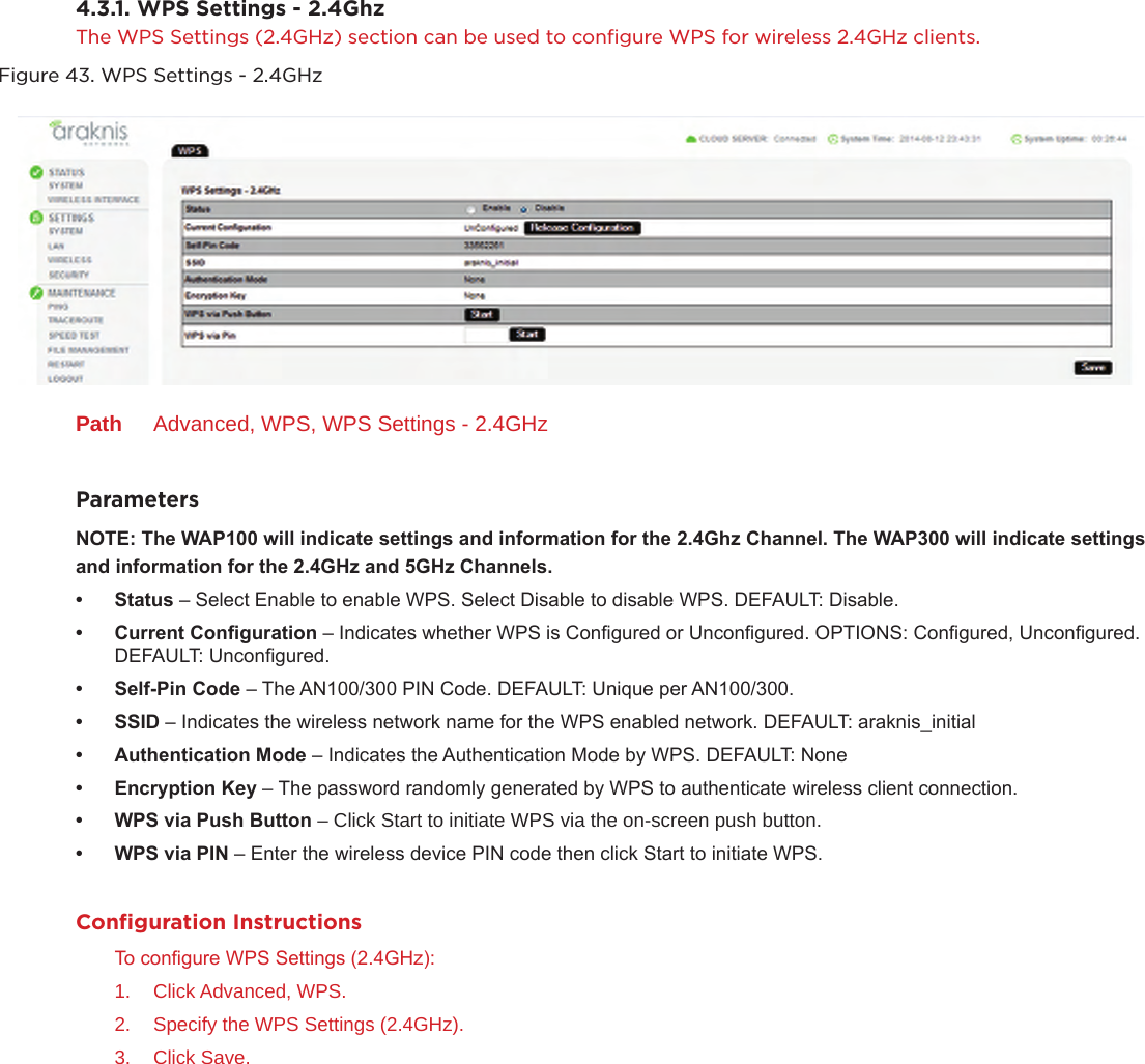
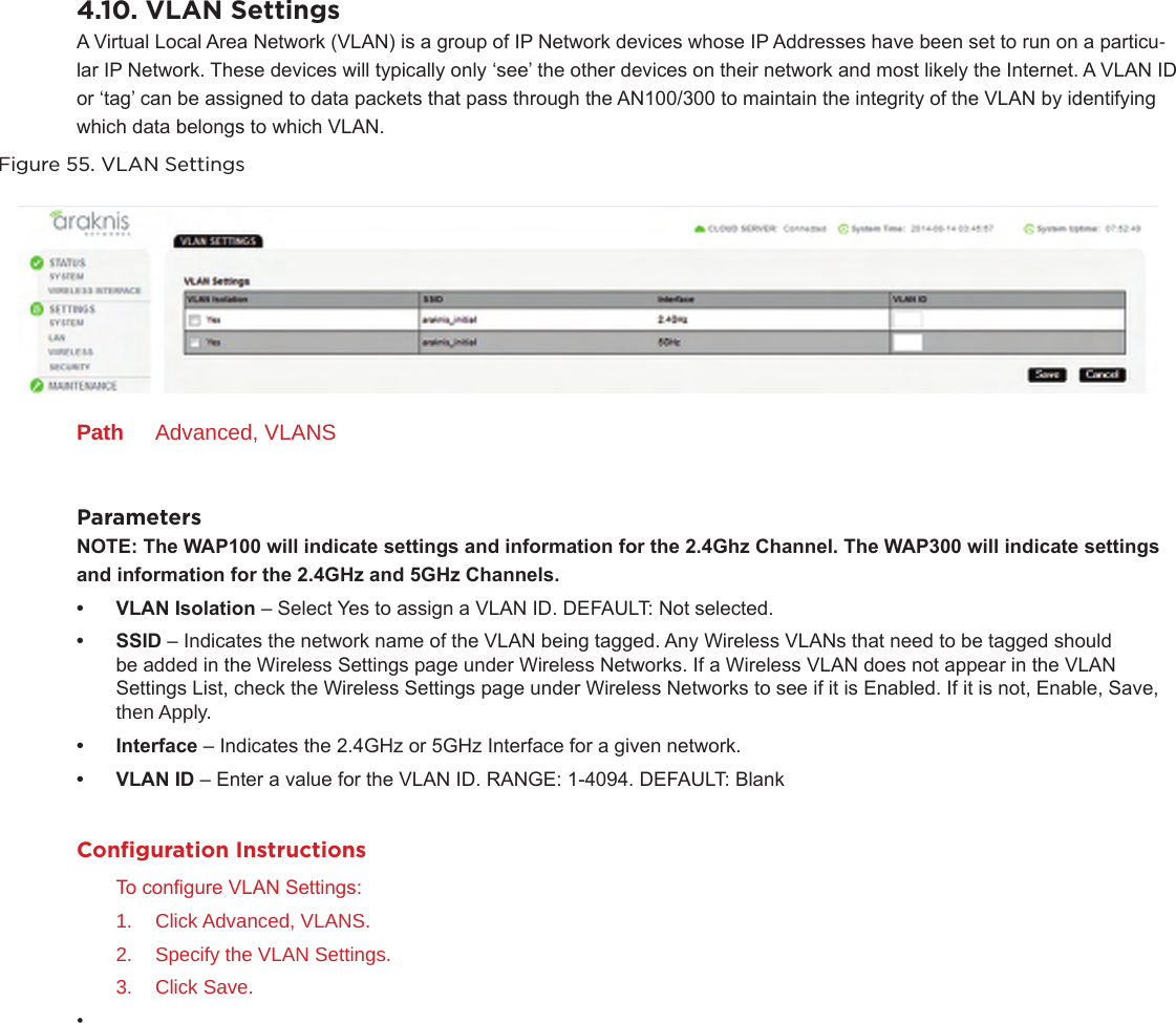
![2.4.3. Email AlertThe Email Alert section allows conguration of the AN100/300 email notication system for status and warnings. Figure 25. Email AlertPath Settings, SecurityParameters• Status– Select Enable to have the AN100/300 send notications to a specic email address in the event of certain abnormal conditions. DEFAULT: Not Selected• From– Enter the Email Address of the sender. DEFAULT: Blank• To– Enter the Email Address of the recipient. DEFAULT: Blank• Subject– Information regarding the nature of the system condition. DEFAULT: [Email-Alert][araknis][88:DC:96:1D:33:6B][Conguration Changed]• EmailAccountUserName– Enter the User Name for the Email Account (Outlook, Gmail, etc) to be used to send the Email Alert. DEFAULT: BlankPassword– Enter the Password for the Email Account (Outlook, Gmail, etc) to be used to send the Email Alert.DEFAULT: BlankSMTPServer– Enter the SMTP Server and Port Number of the Email Client (Outlook, Gmail, etc) to be used to send the Email Alert. DEFAULTS: SMTP Server Blank; Port: 25SecurityMode– Select a security mode for sending Email Alerts. OPTIONS: None, SSL/TLS, STARTTLS DEFAULT: NoneSendTestEmail– Click this button to send a test email to conrm Email Alert settings.Configuration InstructionsTo congure Email Alert:1. Click Settings, Security.2. Specify the Email Alert Settings.3. Click Save.](https://usermanual.wiki/Senao-Networks/AN300APIN.User-Manual-pdf/User-Guide-2391940-Page-26.png)