Senao Networks MP8603 802.11 a/b/g radio card User Manual Manual
Senao Networks, Inc. 802.11 a/b/g radio card Manual
Manual
IEEE 802.11a/
//
/b/g
Wireless MiniPCI Card
User’s Manual V1.0
1
U.S. Regulatory Wireless Notice
Federal Communication Commission Interference Statement
This equipment has been tested and found to comply with the limits for a Class B
digital device, pursuant to Part 15 of the FCC Rules. These limits are designed to
provide reasonable protection against harmful interference in a residential installation.
This equipment generates, uses and can radiate radio frequency energy and, if not
installed and used in accordance with the instructions, may cause harmful
interference to radio communications. However, there is no guarantee that
interference will not occur in a particular installation. If this equipment does cause
harmful interference to radio or television reception, which can be determined by
turning the equipment off and on, the user is encouraged to try to correct the
interference by one of the following measures:
- Reorient or relocate the receiving antenna.
- Increase the separation between the equipment and receiver.
- Connect the equipment into an outlet on a circuit different from that
to which the receiver is connected.
- Consult the dealer or an experienced radio/TV technician for help.
FCC Caution: Any changes or modifications not expressly approved by the party
responsible for compliance could void the user's authority to operate this equipment.
IMPORTANT NOTE:
FCC Radiation Exposure Statement:
This equipment complies with FCC radiation exposure limits set forth for an
uncontrolled environment. This equipment should be installed and operated with
minimum distance 20cm between the radiator & your body.
This transmitter must not be co-located or operating in conjunction with any other
antenna or transmitter.
IEEE 802.11b or 802.11g operation of this product in the U.S.A. is firmware-limited to
channels 1 through 11.

2
This device is intended only for OEM integrators under the following
conditions:
1) The antenna must be installed such that 20 cm is maintained between the
antenna and users, and
2) The transmitter module may not be co-located with any other transmitter or
antenna,
3) For all products market in US, OEM has to limit the operation channels in CH1
to CH11 for 2.4G band by supplied firmware programming tool. OEM shall not
supply any tool or info to the end-user regarding to Regulatory Domain
change.
As long as 3 conditions above are met, further transmitter test will not be required.
However, the OEM integrator is still responsible for testing their end-product for
any additional compliance requirements required with this module installed.
IMPORTANT NOTE: In the event that these conditions can not be met (for
example certain laptop configurations or co-location with another transmitter),
then the FCC authorization is no longer considered valid and the FCC ID can not
be used on the final product. In these circumstances, the OEM integrator will be
responsible for re-evaluating the end product (including the transmitter) and
obtaining a separate FCC authorization.

3
End Product Labeling
This transmitter module is authorized only for use in device where the antenna may
be installed such that 20 cm may be maintained between the antenna and users.
The final end product must be labeled in a visible area with the following: “Contains
FCC ID: U2M-MP8603”.

4
Manual Information To the End User
The OEM integrator has to be aware not to provide information to the end user
regarding how to install or remove this RF module in the user’s manual of the end
product which integrates this module.
The end user manual shall include all required regulatory information/warning as
show in this manual.
CE Declaration of Conformity
For the following equipment: Wireless Adapter
Is herewith confirmed to comply with the requirements set out in the Council Directive on the
Approximation of the Laws of the Member States relating to Electromagnetic Compatibility
(89/336/EEC), Low-voltage Directive (73/23/EEC) and the Amendment Directive (93/68/EEC),
the procedures given in European Council Directive 99/5/EC and 89/3360EEC.
The equipment was passed. The test was performed according to the following European
standards:
EN 300 328 V.1.6.1 (2004-11)
EN 301 893-1 V.1.2.3 (2003-08)
OJ 2005/513/EC
5
Federal Communication Commission Interference Statement............................................1
End Product Labeling ..........................................................................................................3
Manual Information To the End User...................................................................................4
Package Contents................................................................................................................6
Chapter 1: Introduction ........................................................................................................7
1.1 Overview of the product .........................................................................................7
1.2 Features..................................................................................................................7
Chapter 2: Installation Guide...............................................................................................8
2.1 Hardware Installation..............................................................................................8
2.1.1 54/108M Wireless MINIPCI Adapter Hardware Installation.........................8
2.2 Software Installation ...............................................................................................8
2.2.1 Overview ......................................................................................................8
2.2.2 Software Installation for Windows 2000.......................................................8
Chapter 3: Configuration....................................................................................................14
3.1 Current Status.......................................................................................................14
3.2 Profile Management .............................................................................................15
3.2.1 Add or Modify a Configuration Profile ........................................................16
3.2.2 Remove a profile........................................................................................19
3.2.3 Switch another Profile ................................................................................19
3.2.4 Import a Profile...........................................................................................19
3.2.5 Export a Profile...........................................................................................20
3.2.6 Scan Available Networks............................................................................20
3.2.7 Auto Profile Selection Management...........................................................21
3.3 Diagnostics...........................................................................................................22
3.3.1 Check Driver Information ...........................................................................22
3.3.2 Check Receive and Transmit Statistical Information .................................23
Appendix A: Glossary ........................................................................................................24
Appendix B: Economize on power consumption design–.................................................26
6
Package Contents
The following contents should be found in your box:
One 54/108M Wireless MiniPCI Adapter in Bulk Pack
7
Chapter 1: Introduction
1.1 Overview of the product
The Wireless Adapter gives you the flexibility to install in Notebook PC in the most convenient
location available, without the cost of running network cables.
The adapter's auto-sensing capability allows high packet transfer rate of up to 54/108Mbps for
maximum throughput, or dynamic range shifting to lower speeds due to distance or operating
limitations in an environment with a lot of electromagnetic interference. It can also interoperate
with all 11Mbps wireless (802.11b) products. Your wireless communications are protected by up
to 152-bit WEP and WPA encryption for high security.
It adopts 2x to 3x eXtended Range
TM
WLAN transmission technology so that transmission
distance is 2-3 times of traditional 11g/b solutions, up to 855.36m tested in China. Transmission
range is extended to 4-9 times.
It adopts 108M Super G
TM
WLAN Transmission Technology, which offers the highest
throughput performance available on the market today, link rates of up to 108Mbps. In dynamic
108M mode, the device can attach 802.11b, 802.11g and 108Mbps Super G
TM
devices at the
same time in an integrated environment. (Only for 108M Wireless MINIPCI Adapter)
1.2 Features
Complies with IEEE802.11g, IEEE802.11b standards
Adopts 108M Super G
TM
and 2x to 3x eXtended Range
TM
wireless LAN transmission
technologies (108M Super G
TM
only for 108M Wireless MINIPCI Adapter)
Supports WPA data security, IEEE802.1x authentication, TKIP/AES encryption,
64/128/152-bit WEP encryption
Supports 108/54/48/36/24/18/12/9/6/11/5.5/3/2/1Mbps wireless LAN data transfer rates
(108M only for 108M Wireless MINIPCI Adapter)
Provides 32-bit PCI interface (54/108M Wireless MINIPCI Adapter) Supports Ad-Hoc and
Infrastructure modes
Supports roaming between access points when configured in Infrastructure mode
Eases to configure and provides monitoring information
Supports Windows 98, Me, 2000, XP
8
Chapter 2: Installation Guide
2.1 Hardware Installation
2.1.1 54/108M Wireless MINIPCI Adapter Hardware Installation
To install the adapter, follow these steps listed below:
1. Turn off your desktop PC and disconnect the power.
2. Open your PC case and locate an available MINIPCI slot on the motherboard. Remove the
metal slot cover on the back of the PC. Check with your computer manufacturer for
instructions if needed.
3. Slide the MINIPCI Adapter into the PCI slot. Make sure that all of its pins are touching the
slot's contacts. Once the adapter is firmly in place, secure its fastening tab to your PC's
chassis with a mounting screw. Then, close your PC case.
4. Reconnect your PC’s power and turn on your desktop PC.
2.2 Software Installation
2.2.1 Overview
The Adapter’s Setup Wizard will guide you through the Installation procedure for Windows 2000,
XP. The Setup Wizard will install the Wireless Client Utility (WCU) and drivers.
When you install the hardware before installing the software, the system will prompt “Found
New Hardware Wizard” window, click Cancel, and run the Setup Wizard program on the
CD-ROM.
The Setup steps for Windows 2000 and Windows XP are very similar. The following setup steps
are for Windows 2000.
2.2.2 Software Installation for Windows 2000
1. Insert the Resource CD into your CD-ROM drive, click Start and choose Run. In the field
that appears, enter F:\WCU\Win2000_XP\Setup.exe (if “F” is the letter of your CD-ROM
drive), figure 2-1 should then appear.
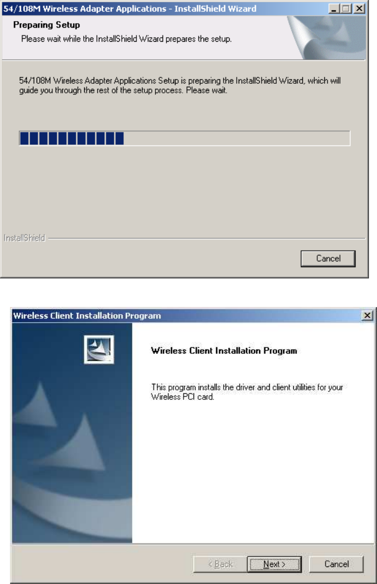
2. You can click Cancel to end the installation on the Preparing Setup screen, figure 2-1.
Otherwise, the Setup Wizard will display a screen similar to that shown in figure 2-2 after a
moment.
9
Figure 2-1 Wireless Client Utility – Install Shield Wizard
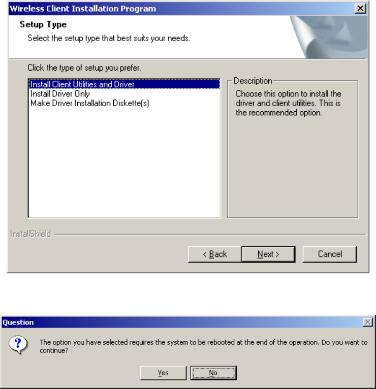
3. To continue, click Next on the screen, figure 2-2. Click Cancel to end the Installation.
Figure 2-2 Wireless Client Utility Installation Program
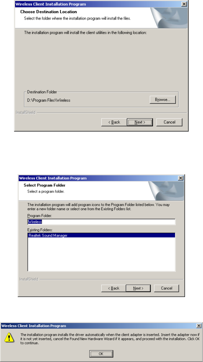
4. The Setup Wizard will ask you to choose a Setup type in figure 2-3. It is recommended that
you select Install Client Utilities and Driver. Select Install Driver Only to install driver
only, select Make Driver Installation Diskette(s) to make the diskette(s) as the installation
driver. Select Install Client Utilities and Driver and click Next to continue the Installation.
10
Click Back to return to the previous page, or click Cancel to end the Installation.
Figure 2-3 Select the setup type
5. Figure 2-4 should appear. Click Yes to continue the Installation, or click No to end the
Installation.
Figure 2-4 Question
6. Click Browse to change the destination location for the software in figure 2-5. Click Next to
continue the Installation. Click Back to return to the previous page, or click Cancel to end
the Installation.
11
Figure 2-5 Choose Destination Location
7. The Setup Wizard will ask you to create a new folder name or select one from the Existing
Folders list shown in figure 2-6. It is recommended that you keep the default value. Click
Next to continue the Installation. Click Back to return to the previous page, or click Cancel
to end the Installation.
Figure 2-6 Select a Program Folder
8. The Setup Wizard will notify you of how to proceed with the installation, shown in figure 2-7.
Click OK to continue the Installation.
Figure 2-7 Information prompt
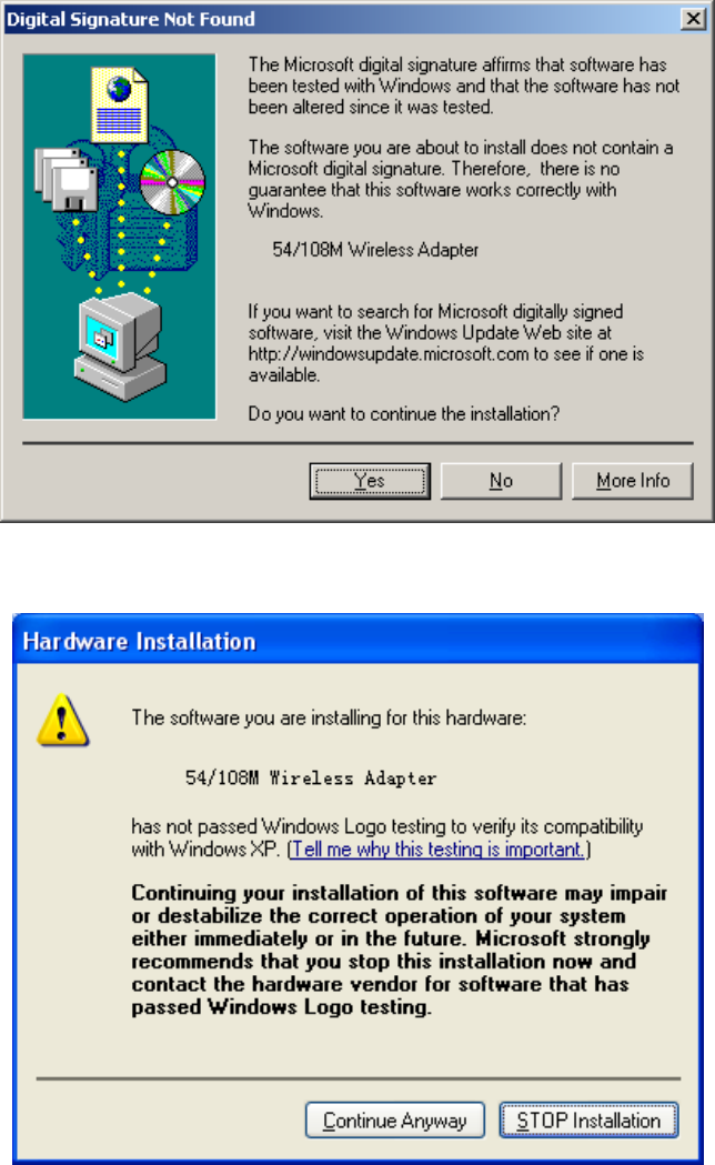
9. While files are copying, you will see a warning box, shown in figure 2-8. Please select YES
to continue installation. Our drivers have been tested thoroughly, and are able to work with
the operating system.
12
Figure 2-8 Windows 2000 Warning Box
Note: In Windows XP, the warning box is similar to that shown figure 2-8a. Please select
Continue Anyway to continue installation.
Figure 2-8a Windows XP Warning Box
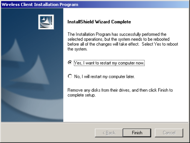
10. After the files have been successfully copied, the screen in figure 2-9 will appear. Click
Finish to reboot the system.
13
Figure 2-9 Finish
14
Chapter 3: Configuration
The Wireless Adapter can be configured by Wireless Client Utility (WCU). This chapter
describes how to configure your Wireless Adapter for wireless connectivity on your Wireless
Local Area Network (WLAN) and use the data security encryption features.
After Installing the Adapter, the Adapter’s tray icon will appear in your system tray. It
appears at the bottom of the screen, and shows the signal strength using color and the received
signal strength indication (RSSI).
If the icon is gray, there is no connection.
If the icon is red, there is poor signal strength and the RSSI is less than 5dB.
If the icon is yellow, there is poor signal strength and the RSSI is between 5dB and
10dB.
If the icon is green, there is good signal strength and the RSSI is between 10dB and
20dB.
If the icon is green, there is excellent signal strength and the RSSI is more than 20dB.
Double-click the icon and the WCU utility will run. You can also run the utility by clicking the
Start>Program>Wireless>Wireless Client Utility. The WCU utility provides a complete and
easy to use set of tools to:
Display current status information
Edit and add configuration profiles
Display current diagnostics information
The section below introduces these above capabilities.
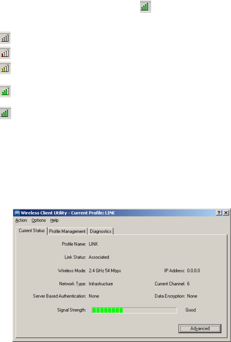
3.1 Current Status
The Current Status tab contains general information about the program and its operations. The
Current Status tab does not require any configurations.
Figure 3-1 Current Status
15
The following table describes the items found on the Current Status screen.
Profile Name - The name of current selected configuration profile. Set up the configuration
name on the General tab of Profile Management.
Link Status - Shows whether the station is associated to the wireless network.
Wireless Mode - Displays the wireless mode. Configure the wireless mode on the
Advanced tab of Profile Management.
Network Type - The type of network and the station currently connected. The options
include:
• Infrastructure (access point)
• Ad Hoc
Configure the network type on the Advanced tab of Profile Management.
IP Address - Displays the computer’s IP address.
Current Channel - Shows the currently connected channel.
Data Encryption - Displays the encryption type the driver is using. Configure the
encryption type on the Security tab of Profile Management.
Server Based Authentication - Shows whether server based authentication is used.
Signal Strength - Shows the strength of the signal.
Note: In the WCU utility, access the General tab, Security tab and Advanced tab by clicking
New or Modify on the Profile Management tab.
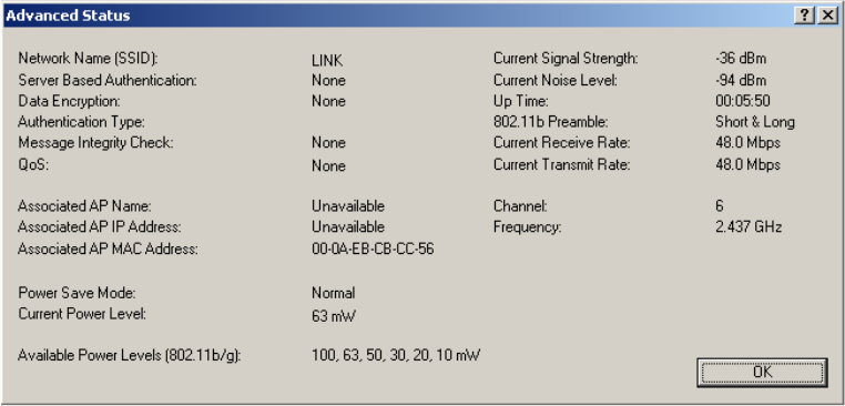
Click Advanced to see advanced information about the program and its operations. For more
information, please refer to the help file of the utility.
Figure 3-2 Advance Status
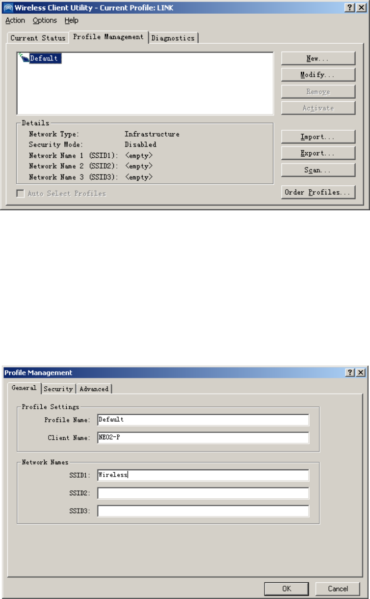
3.2 Profile Management
Click the Profile Management tab of the WCU Utility and the Profile Management screen will
appear, figure 3-3. The Profile Management screen provides tools to:
Add a profile
Edit a profile
Remove a profile
Switch to another Profile
Import a Profile
Export a Profile
Scan Available Networks
Order profiles
16
Figure 3-3 Profile Management tab
3.2.1 Add or Modify a Configuration Profile
To add a new configuration profile, click New on the Profile Management tab. To modify a
configuration profile, select the configuration from the Profile list and click Modify.
The Profile Management dialog box will display a screen similar to that shown in Figure 3-4.
1. Edit the General tab
Profile Name - Identifies the configuration profile. This name must be unique. Profile
names are not case-sensitive.
Client Name - Identifies the client machine.
Network Names (SSIDs) - The IEEE 802.11 wireless network name. This field has a
maximum limit of 32 characters.
Figure 3-4 General Tab of Profile Management
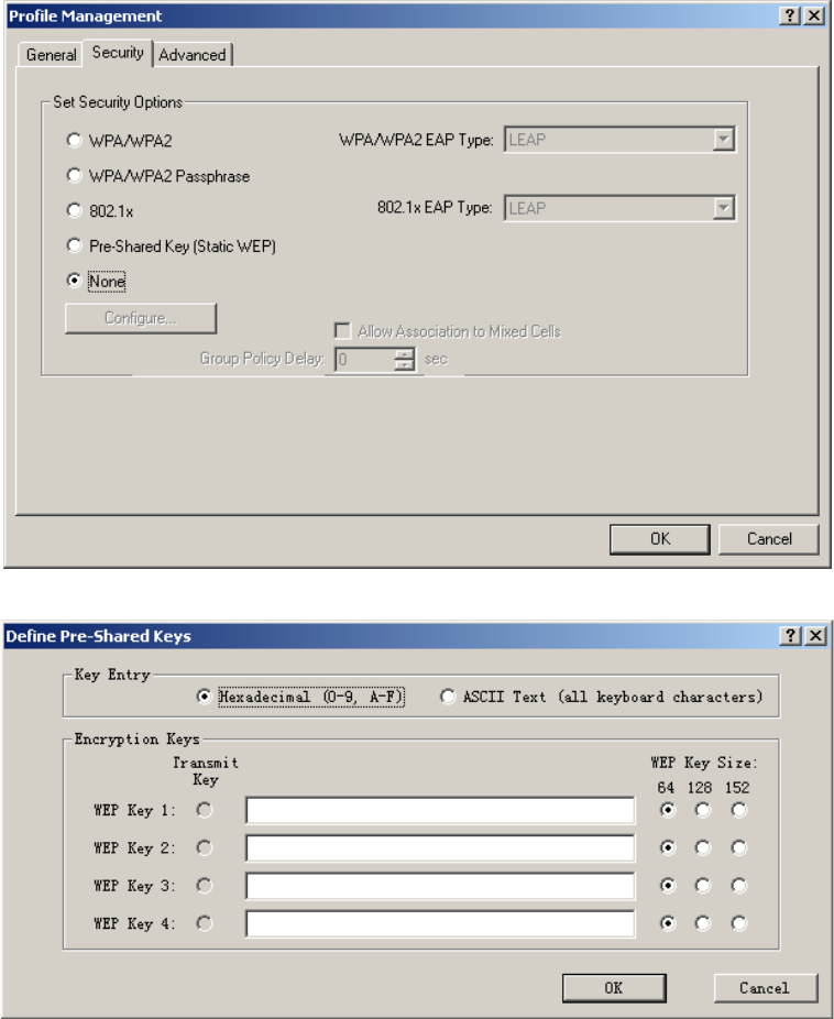
2. Edit the Security tab
17
Edit the fields in the Security tab of Profile Management to configure the profile. To define the
security mode, select the radio button of the desired security mode.
WPA - Wi-Fi Protected Access
WPA Passphrase - Wi-Fi Protected Access Passphrase
802.1x - Enables 802.1x security.
Shared Key (Static WEP) - Enables the use of shared keys that are defined on both the
access point and the station. To define shared encryption keys, choose the Shared Key
radio button and click Configure to fill in the Define Shared Keys window.
None: No security (not recommended).
Note: If the access point that the wireless adapter is associating to has WEP set to Optional
and the client has WEP enabled, make sure that Allow Association to Mixed Cells is checked on
the Security Tab to allow association. To complete WEP encryption configuration, you must
select the 802.11 Authentication Mode as appropriate on the Advanced tab of this Profile
Management dialog.
Figure 3-5 Security tab of Profile Management
Figure 3-6 Define Shared Keys
18
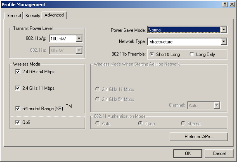
3. Edit the Advanced tab
Transmit Power Level - Selects the transmit power level for 802.11b/g in mW. Actual
transmit power may be limited by regulatory domain or hardware limitations.
Power Save Mode -
• Maximum - Selects maximum mode to let the access point buffer incoming messages
for the wireless adapter. The adapter will detect the access point if any messages are
waiting periodically.
• Normal - In Normal mode, the adapter will be switched to maximum mode
automatically when no large packets are retrieved.
• Off - turns power saving off, thus powering up the wireless adapter continuously for a
short message response time.
802.11b Preamble - Specifies the preamble setting in 802.11b. The default setting is
Short & Long (access point mode), which allows both short and long headers in the
802.11b frames. The adapter can only use short radio headers if the access point supports
and uses them. Set to Long Only to override allowing short frames.
Wireless Mode - Specifies 2.4 GHz 54 Mbps, 2.4 GHz 11 Mbps, or Super G (Only for
108M Wireless MINIPCI Adapter) operation in an access point network. The wireless
adapter must match the wireless mode of the access point with which it associates
Wireless Mode when Starting an Ad Hoc Network - Specifies Super G (Only for 108M
Wireless MINIPCI Adapter) or 2.4 GHz 54/11Mbps to start an Ad Hoc network if no
matching network name is found after scanning all available modes. This mode also allows
the selection of the channel the wireless adapter uses. The channels available depend on
the regulatory domain. If the adapter finds no other ad hoc adapters, the channel that the
adapter starts the ad hoc network with will be selected automatically. The wireless adapter
must match the wireless mode and channel of the clients it associates.
802.11 Authentication Mode - Select which mode the wireless adapter uses to
authenticate to an access point:
• Automatic causes the adapter to attempt authentication using shared, but switches it to open
authentication if shared fails.
• Open System enables an adapter to attempt authentication regardless of its WEP settings. It will
only associate with the access point if the WEP keys on both the adapter and the access point
match.
•
Shared-key only allows the adapter to associate with access points that have the same WEP key.
For infrastructure (access point) networks, click Preferred APs… to specify up to four access
points to the client adapter that attempts to be associated to the access points.
19
Figure 3-7 Advanced tab of Profile Management
3.2.2 Remove a profile
1. Go to the Profile Management tab.
2. Select the profile name to remove in the Profiles List.
3. Click Remove.
3.2.3 Switch another Profile
1. Go to the Profile Management tab.
2. Click on the profile name in the Profiles List.
3. Click Activate.
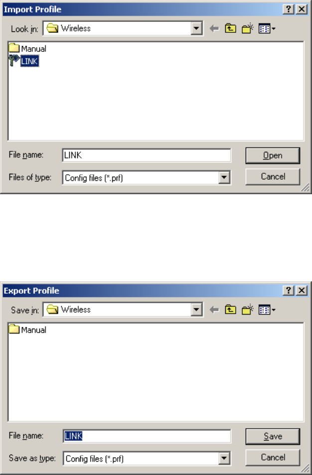
3.2.4 Import a Profile
1. From the Profile Management tab, click Import…. The Import Profile will then appear.
2. Browse to the directory where the profile is located.
3. Highlight the profile name.
4. Click Open, the imported profile will then appear in the Profiles List.
20
Figure 3-8 Import Profile Dialog
3.2.5 Export a Profile
1. From the Profile Management tab, highlight the profile to export.
2. Click Export…, the Export Profile window will then appear.
3. Browse the directory to export the profile to.
4. Click Save. The profile should then be exported to the specified location.
Figure 3-9 Export Profile Dialog
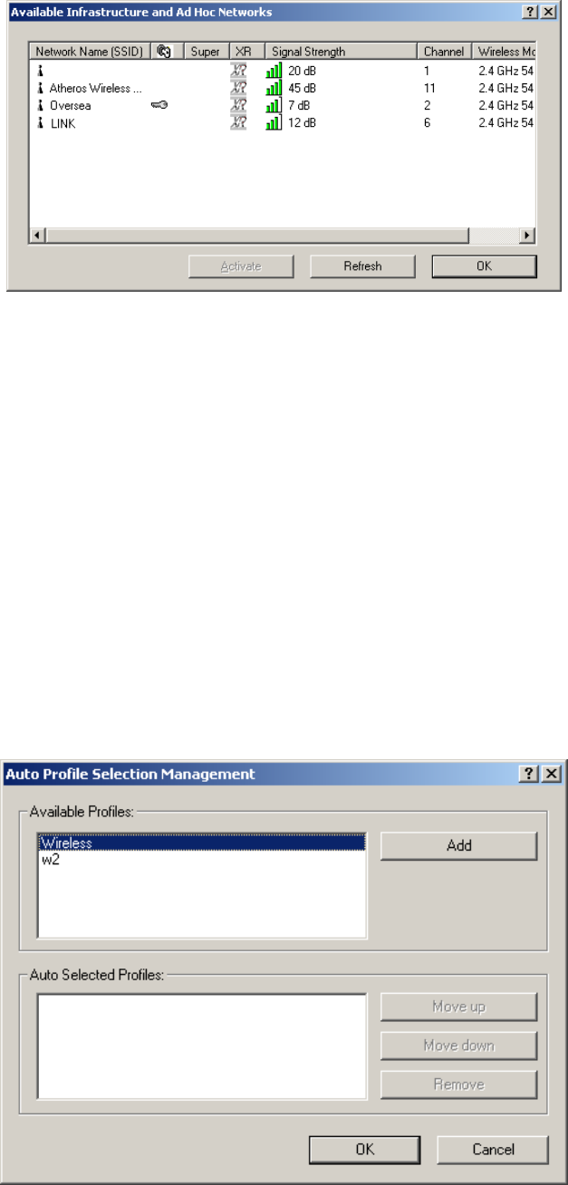
3.2.6 Scan Available Networks
1. Click Scan on the Profile Management, the Available Infrastructure and Ad Hoc Networks
window will appear.
2. Click Refresh to refresh the list at any time.
3. Highlight a network name and click Activate to connect an available network. If no
configuration profile exists for that network, the Profile Management window will open the
General tab. Fill in the Profile name and click OK to create the configuration profile for that
network.
21
Figure 3-10 Scan Available Networks Dialog
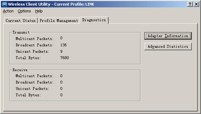
3.2.7 Auto Profile Selection Management
The auto selection feature allows the wireless adapter to automatically select a profile from the
list of profiles and use it to connect to the network. To add a new profile into the Auto Selected
Profiles list, please follow these steps.
1. On the Profile Management tab, click Order Profiles….
2. The Auto Profiles Selection management window will appear, with a list of all created
profiles in the Available Profiles box.
3. Highlight the profiles to add to auto profile selection, and click Add. The profile will appear
in the Auto Selected Profiles box.
4. Highlight a profile in the Auto Selected Profiles box.
5. Click Move Up or Move Down as appropriate. Note: The first profile in the Auto Selected
Profiles box has highest priority, and the last profile has lowest priority.
6. Click OK.
7. Check the Auto Select Profiles checkbox on the Profile Management tab.
Note: When auto profile selection is enabled by checking Auto Select Profiles on the Profile
Management tab, the client adapter will scan for an available network. The profile with the
highest priority and the same SSID as one of the found networks will be used to connect to the
network. If the connection fails, the client adapter will try the next highest priority profile that
matches the SSID until an available network is found.
22
Figure 3-11 Auto Profile Selection Management Dialog
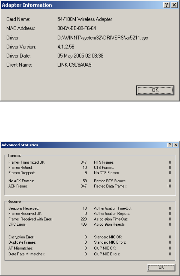
3.3 Diagnostics
The Diagnostics tab of the Wireless Client Utility (WCU) provides buttons used to retrieve
receiving and transmitting statistics. The Diagnostics tab does not require any configuration.
The Diagnostics tab lists the following receive and transmit diagnostics for frames received or
transmitted by the wireless network adapter:
Multicast frames transmitted and received
Broadcast frames transmitted and received
Unicast frames transmitted and received
Total bytes transmitted and received
Figure 3-12 Diagnostics tab
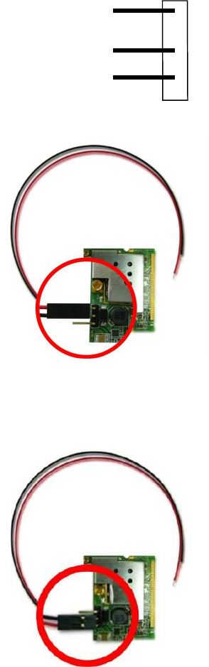
3.3.1 Check Driver Information
The Adapter Information contains general information about the wireless network adapter and
the Network Driver Interface Specification (NDIS) driver. Access the adapter information from
the Diagnostics tab.
Card Name - The name of the wireless network adapter.
MAC Address - The MAC address of the wireless network adapter.
Driver - The driver name and path of the wireless network adapter driver.
Driver Version - The version of the wireless network adapter driver.
Driver Date - The creation date of the wireless network adapter driver.
Client Name - The name of the client computer.
23
Figure 3-13 Adapter Information
3.3.2 Check Receive and Transmit Statistical Information
The Advanced Statistics show receiving and transmitting statistical information for the
following receive and transmit diagnostics for frames received by or transmitted to the wireless
network adapter.
Figure 3-14 Advanced Statistics
24
Appendix A: Glossary
108M Super G
TM
WLAN Transmission Technology - 108M Super G
TM
WLAN
Transmission Technology employs multiple performance-enhancing techniques including
packet bursting, fast frames, data compression, and dynamic turbo mode that combine to
improve the throughput and range of wireless networking products. Users can experience
link rates of up to 108Mbps, twice the industry-standard maximum data link rate of 54Mbps,
while preserving full compatibility with traditional 802.11g or 802.11b networks. 108M
Super G
TM
products offer the highest throughput performance available on the market
today. In dynamic 108M mode, the device can attach 802.11b, 802.11g and 108Mbps
Super G
TM
devices at the same time in an integrated environment.
2x to 3x eXtended Range
TM
WLAN Transmission Technology - The WLAN device with
2x to 3x eXtended Range
TM
WLAN transmission technology make its sensitivity up to 105 dB,
which gives users the ability to have robust, longer-range wireless connections. With this
range-enhancing technology, a 2x to 3x eXtended Range
TM
based client and access point can
maintain a connection at as much as three times the transmission distance of traditional 802.11b
and 802.11g products, for a coverage area that is up to nine times greater. A traditional 802.11b
and 802.11g product transmission distance is about 300m, A 2x to 3x eXtended Range
TM
based
client and access point can maintain a connection transmission distance may be up to 830m.
802.11b - The 802.11b standard specifies a wireless product networking at 11 Mbps using
direct-sequence spread-spectrum (DSSS) technology and operating in the unlicensed
radio spectrum at 2.4GHz, and WEP encryption for security. 802.11b networks are also
referred to as Wi-Fi networks.
802.11g - specification for wireless networking at 54 Mbps using direct-sequence
spread-spectrum (DSSS) technology, using OFDM modulation and operating in the
unlicensed radio spectrum at 2.4GHz, and backward compatibility with IEEE 802.11b
devices, and WEP encryption for security.
Ad-hoc Network - An ad-hoc network is a group of computers, each with a wireless
adapter, connected as an independent 802.11 wireless LAN. Ad-hoc wireless computers
operate on a peer-to-peer basis, communicating directly with each other without the use of
an access point. Ad-hoc mode is also referred to as an Independent Basic Service Set
(IBSS) or as peer-to-peer mode, and is useful at a departmental scale or SOHO operation.
DSSS (Direct-Sequence Spread Spectrum) - DSSS generates a redundant bit pattern for
all data transmitted. This bit pattern is called a chip (or chipping code). Even if one or more
bits in the chip are damaged during transmission, statistical techniques embedded in the
receiver can recover the original data without the need for retransmission. To an
unintended receiver, DSSS appears as low power wideband noise and is rejected (ignored)
by most narrowband receivers. However, to an intended receiver (i.e. another wireless
LAN endpoint), the DSSS signal is recognized as the only valid signal, and interference is
inherently rejected (ignored).
FHSS (Frequency Hopping Spread Spectrum) - FHSS continuously changes (hops) the
carrier frequency of a conventional carrier several times per second according to a
pseudo-random set of channels. Because a fixed frequency is not used, and only the transmitter
and receiver know the hop patterns, interception of FHSS is extremely difficult.
Infrastructure Network - An infrastructure network is a group of computers or other
devices, each with a wireless adapter, connected as an 802.11 wireless LAN. In
infrastructure mode, the wireless devices communicate with each other and to a wired
network by first going through an access point. An infrastructure wireless network
connected to a wired network is referred to as a Basic Service Set (BSS). A set of two or
more BSS in a single network is referred to as an Extended Service Set (ESS).
Infrastructure mode is useful at a corporation scale, or when it is necessary to connect the
25
wired and wireless networks.
Spread Spectrum - Spread Spectrum technology is a wideband radio frequency technique
developed by the military for use in reliable, secure, mission-critical communications
systems. It is designed to trade off bandwidth efficiency for reliability, integrity, and security.
In other words, more bandwidth is consumed than in the case of narrowband transmission,
but the trade off produces a signal that is, in effect, louder and thus easier to detect,
provided that the receiver knows the parameters of the spread-spectrum signal being
broadcast. If a receiver is not tuned to the right frequency, a spread-spectrum signal looks
like background noise. There are two main alternatives, Direct Sequence Spread Spectrum
(DSSS) and Frequency Hopping Spread Spectrum (FHSS).
SSID - A Service Set Identification is a thirty-two character (maximum) alphanumeric key
identifying a wireless local area network. For the wireless devices in a network to
communicate with each other, all devices must be configured with the same SSID. This is
typically the configuration parameter for a wireless PC card. It corresponds to the ESSID in
the wireless Access Point and to the wireless network name.
WEP (Wired Equivalent Privacy) - A data privacy mechanism based on a 64-bit or 128-bit
or 152-bit shared key algorithm, as described in the IEEE 802.11 standard.
Wi-Fi - A trade name for the 802.11b wireless networking standard, given by the Wireless
Ethernet Compatibility Alliance (WECA, see http://www.wi-fi.net), an industry standards
group promoting interoperability among 802.11b devices.
WLAN (Wireless Local Area Network) - A group of computers and associated
devices communicate with each other wirelessly, which network serving users
are limited in a local area.
WPA (Wi-Fi Protected Access) - A wireless security protocol use TKIP (Temporal Key Integrity
Protocol) encryption, which can be used in conjunction with a RADIUS server.
26
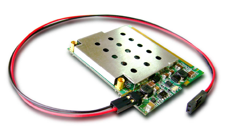
Appendix B: Economize on power consumption design–
Auto-switching mechanism with a jump wire (Plug and Play)
PIN assignment of the PIN Header on mini-PCI
Selection A: External DC power in, support V+ 5V
a. Red pin connects to V+ 5V, Max power < 5W
b. Black pin connects to GND
Selection B: External DC power in, support V+ 9 ~ 24V
a. Red pin connects to V+ 9 ~ 24V , Max power < 5W
b. Black pin connects to GND
Selection C: No power saving mode. Remove the Jump wire
Power supply from mini-PCI
slot (3.3 V) only.
V+ 5V
GND
V+ 9 ~24V