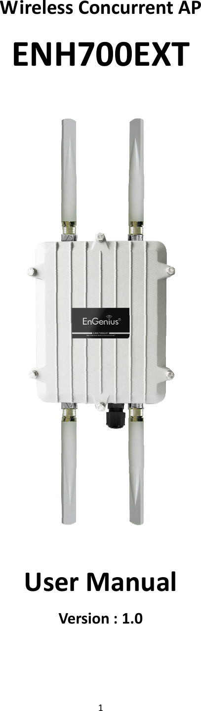
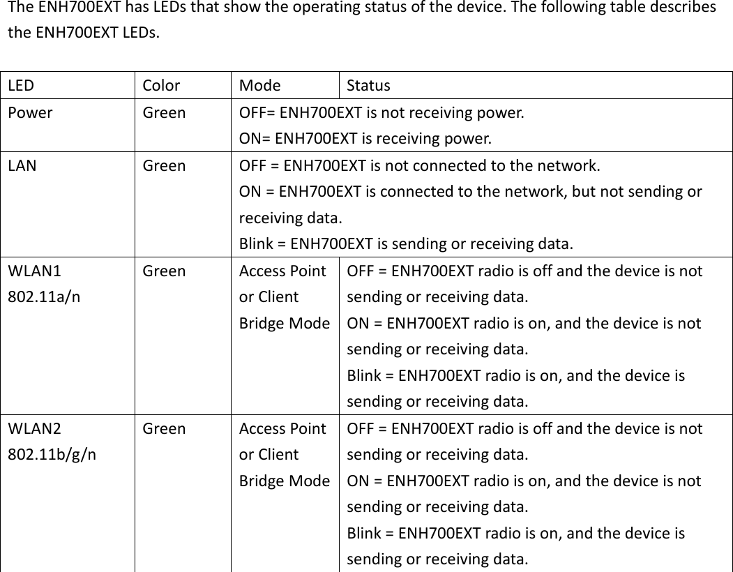
Senao Networks NH700EXT Wireless Concurrent AP User Manual User s manual
Senao Networks, Inc. Wireless Concurrent AP User s manual
UserManual.wiki
>
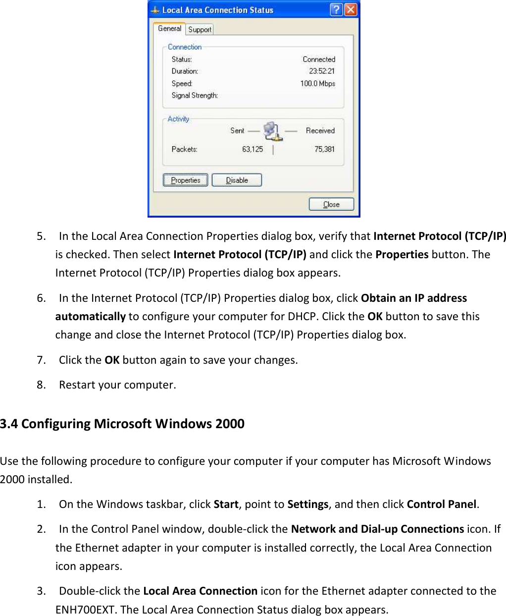
Senao Networks
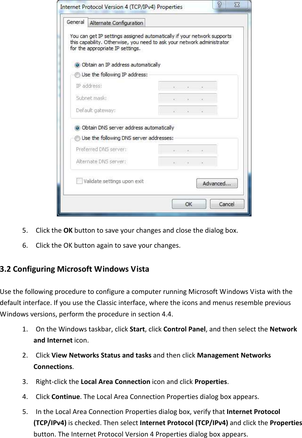
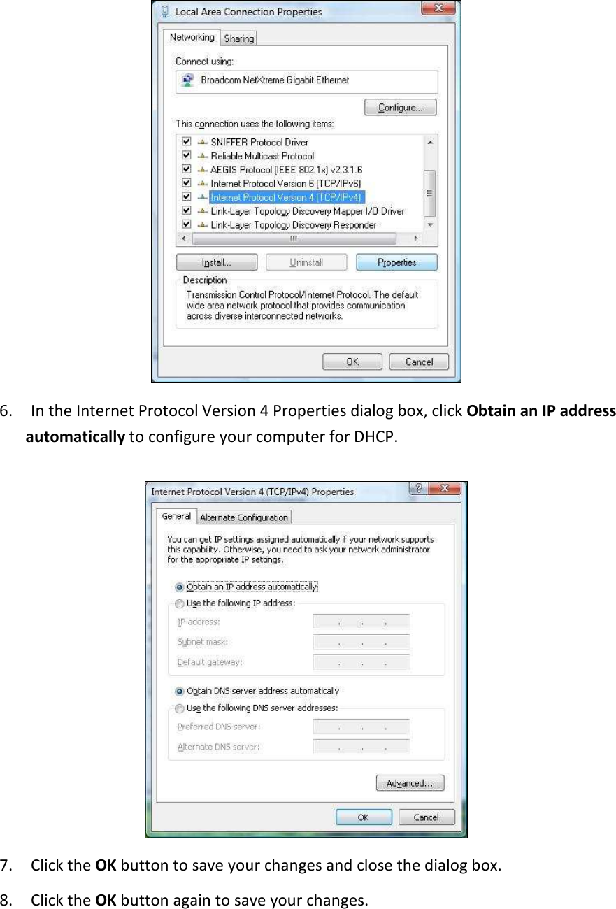
>
NH700EXT User Manual
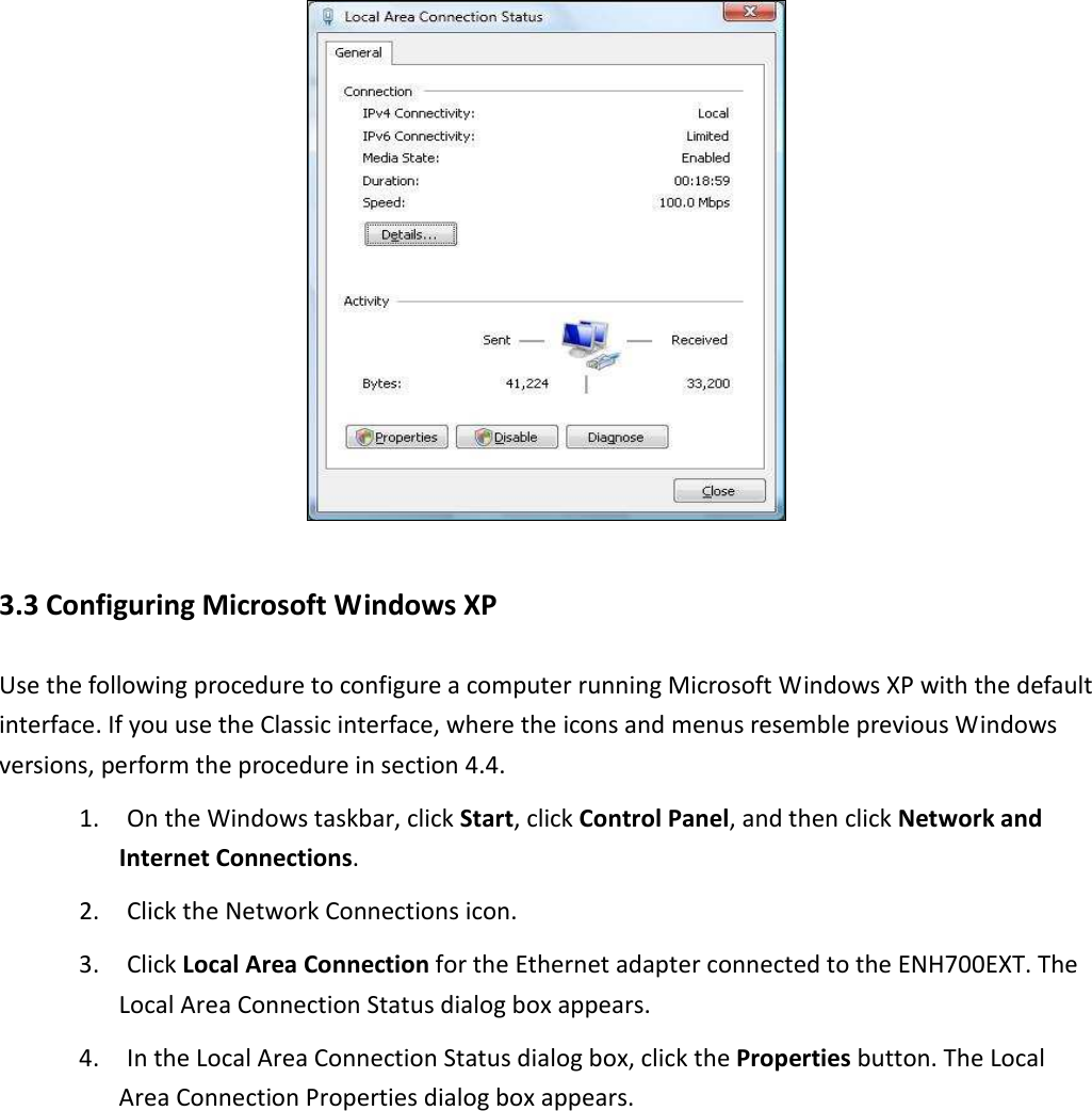
User Manual
Navigation menu
Upload a User Manual
Namespaces
Wiki Guide
HTML
PDF
Info
Views
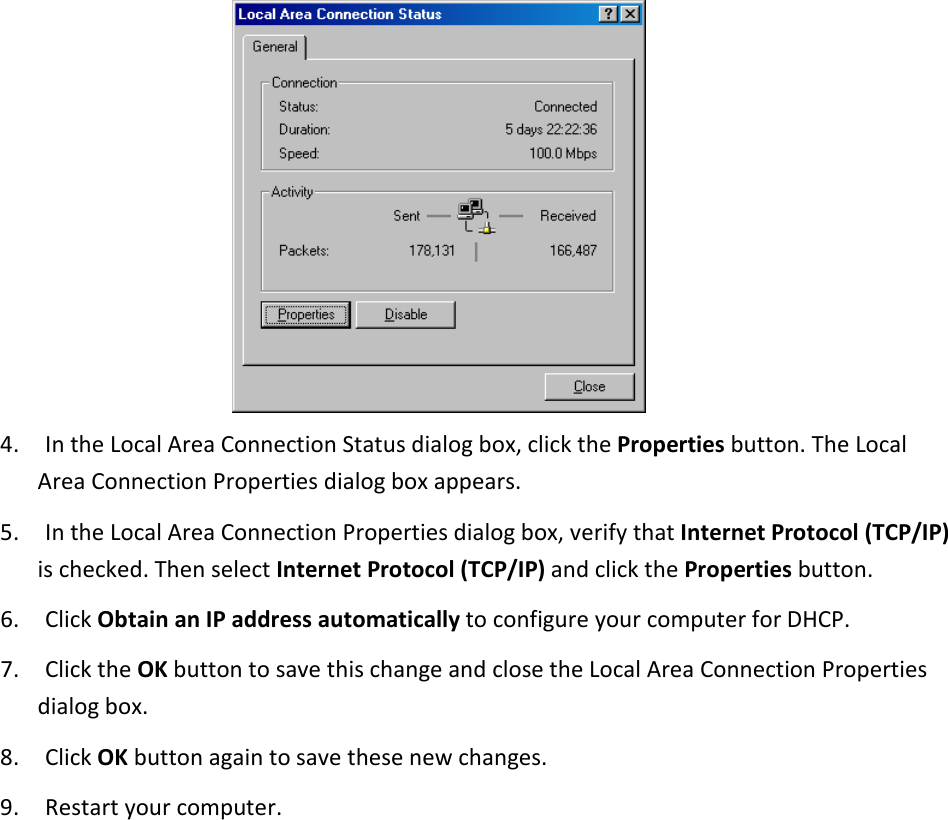
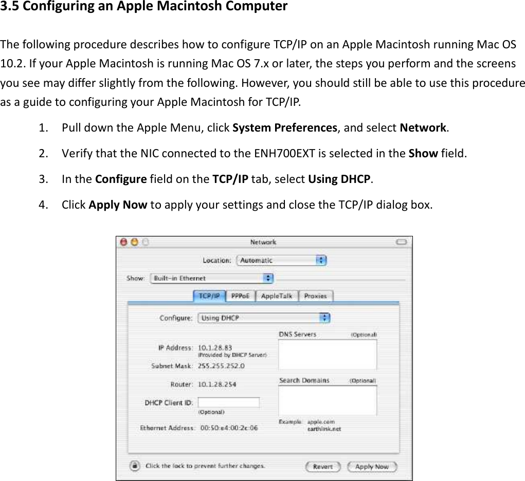
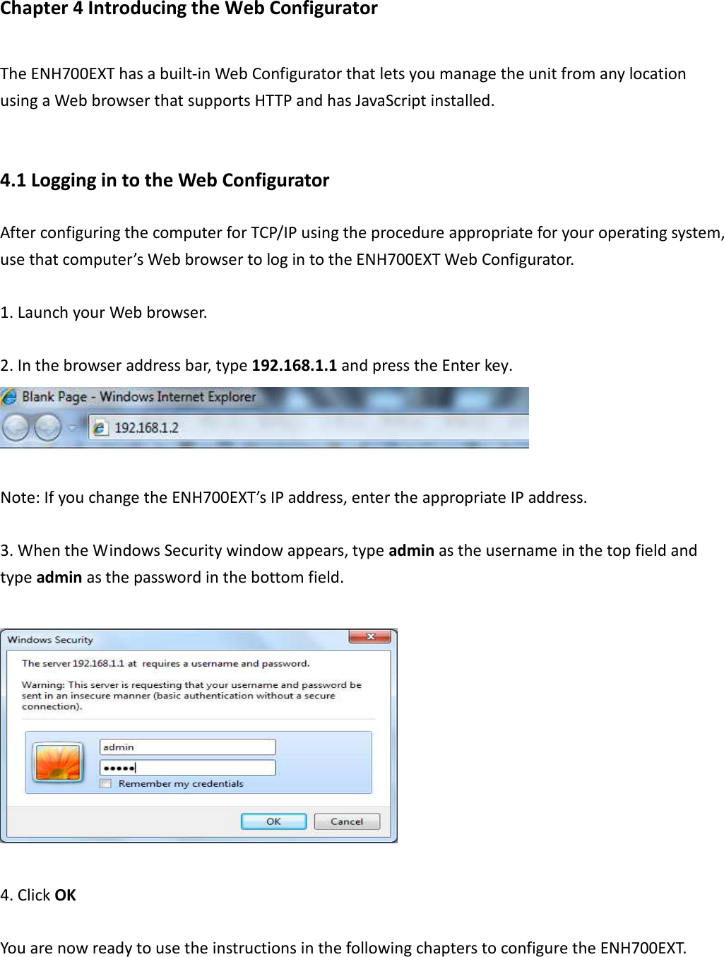
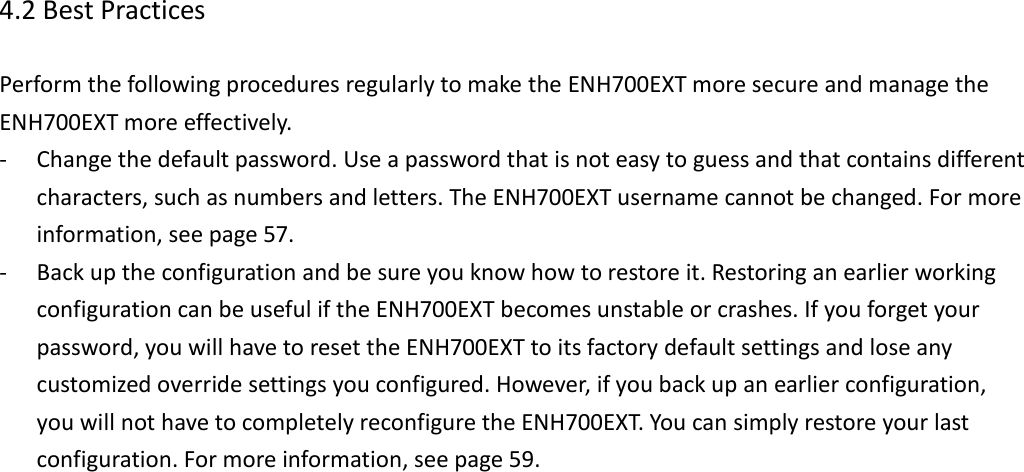
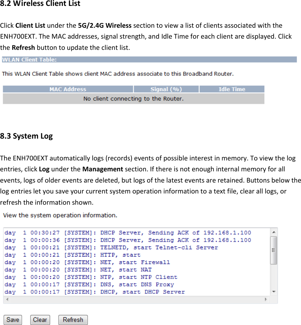
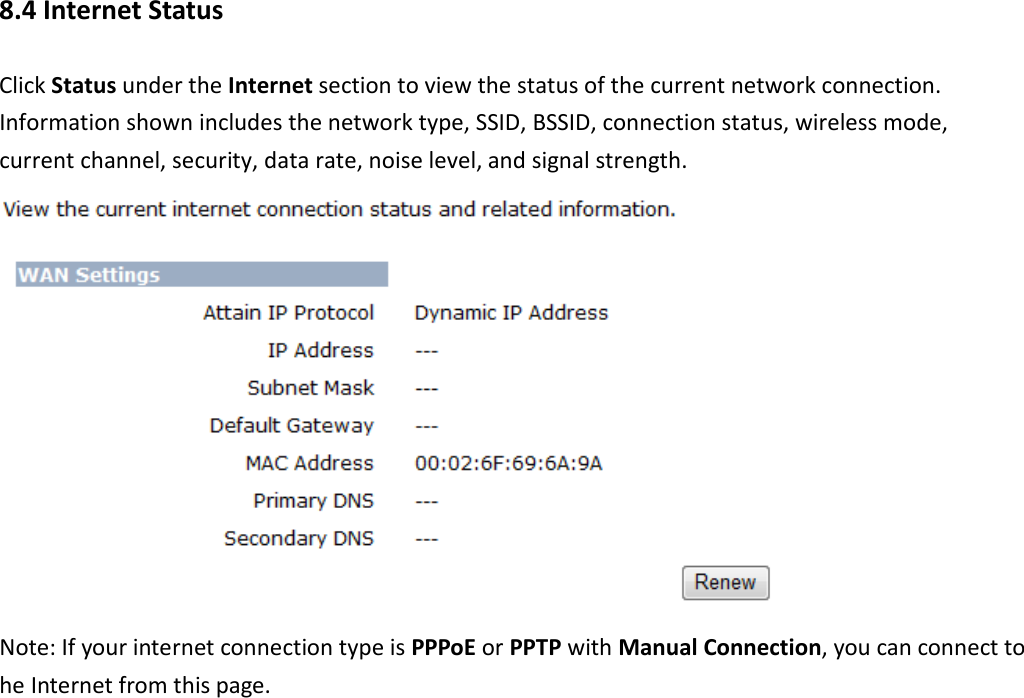
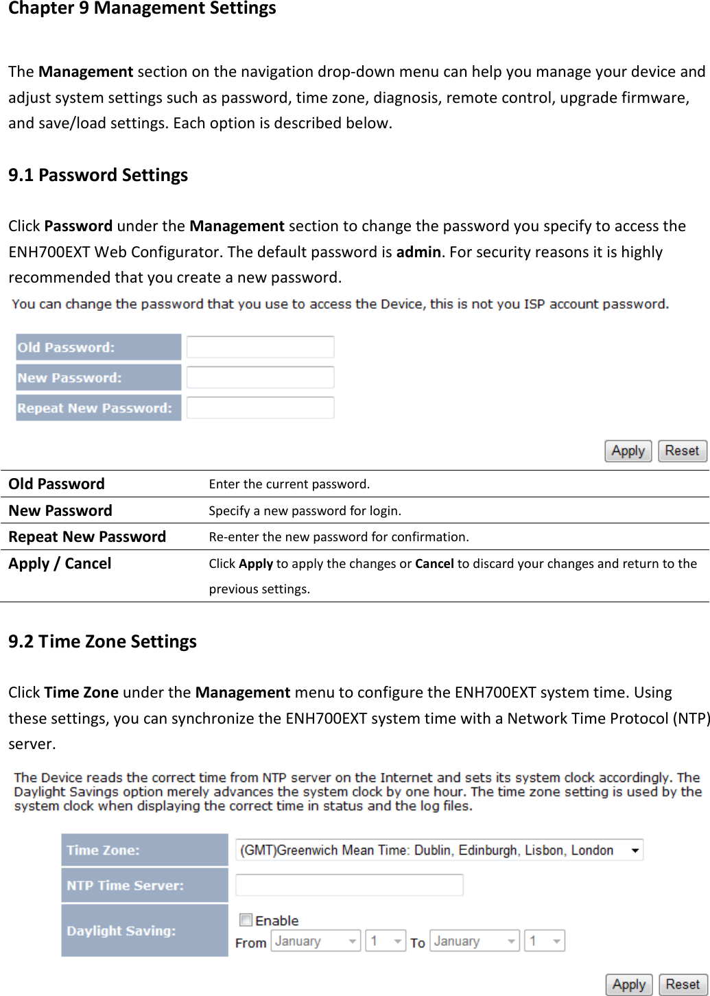
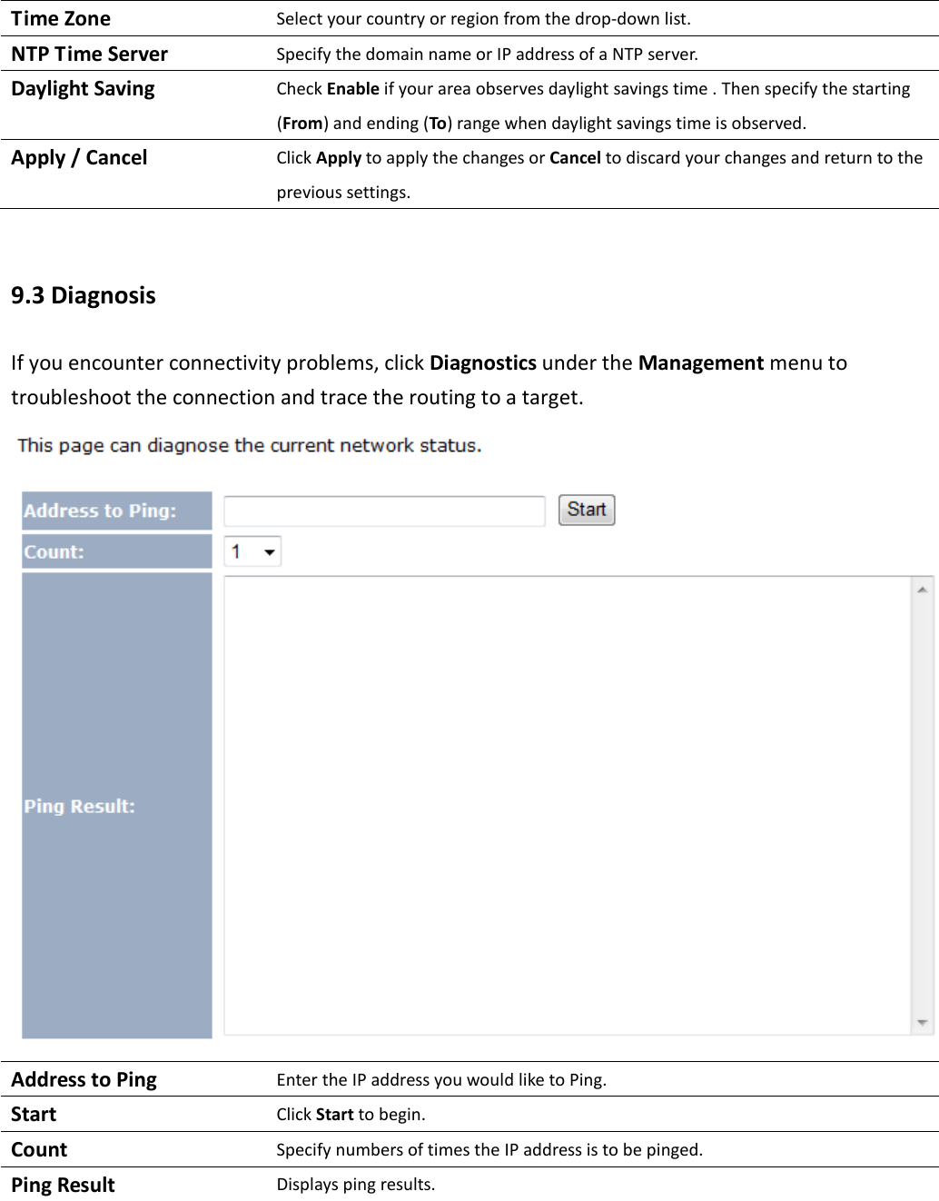
User Manual
Discussion / Help
Navigation