Senao Networks OC5510 Wireless Multi-Function AP User Manual EOC5510 UserManual v1 0 20100317C
Senao Networks, Inc. Wireless Multi-Function AP EOC5510 UserManual v1 0 20100317C
UserManual.wiki
>
Senao Networks
>
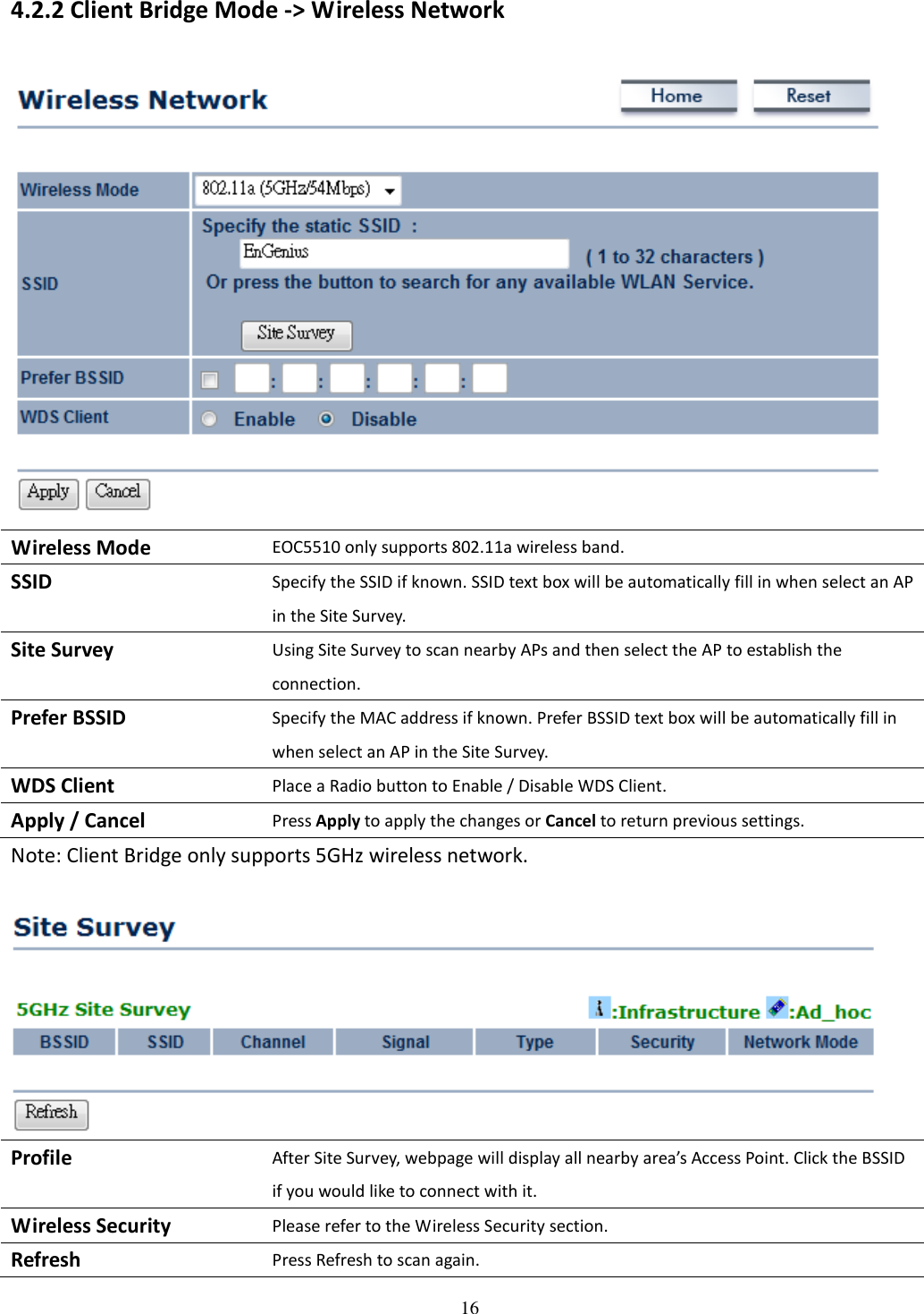
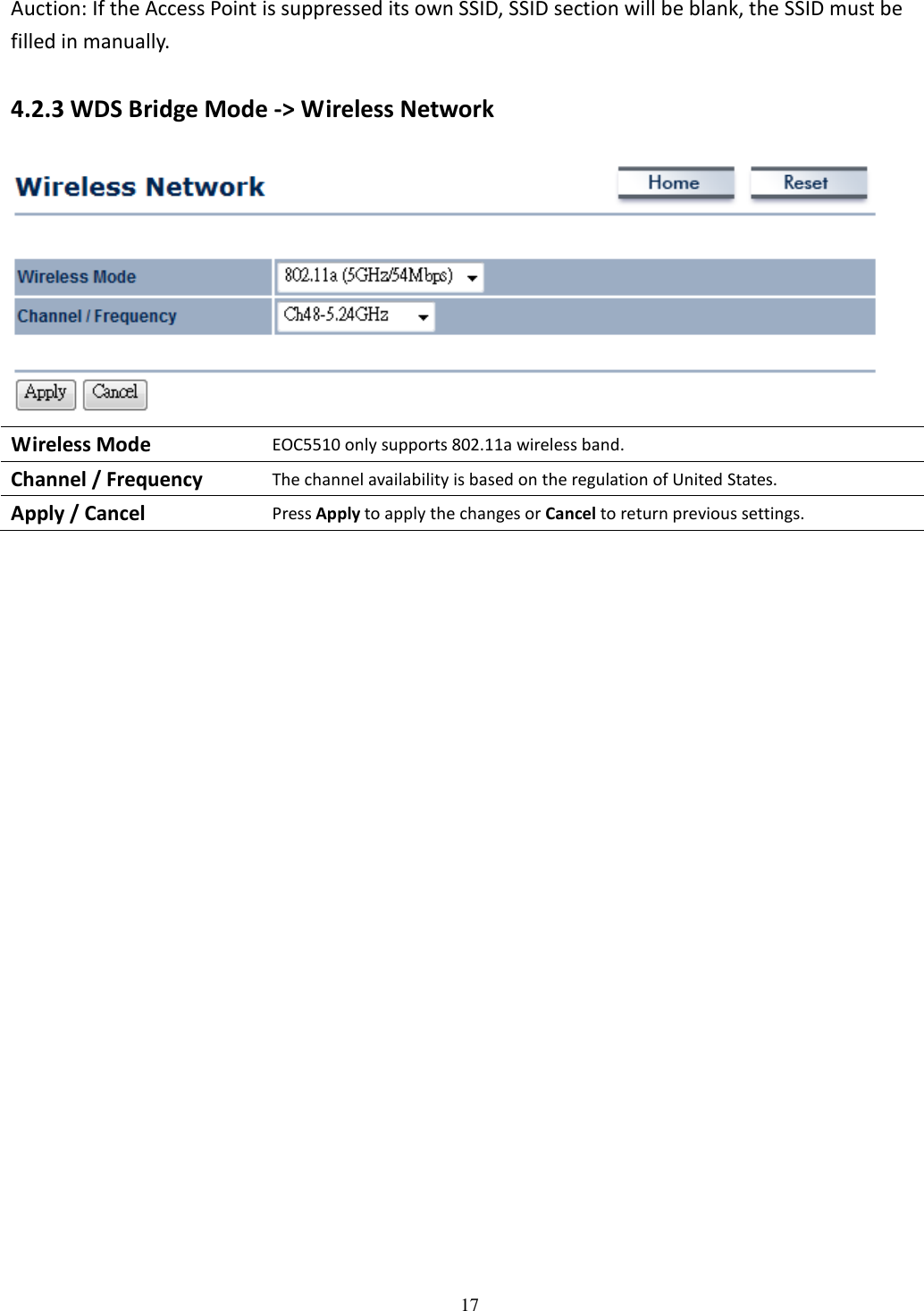
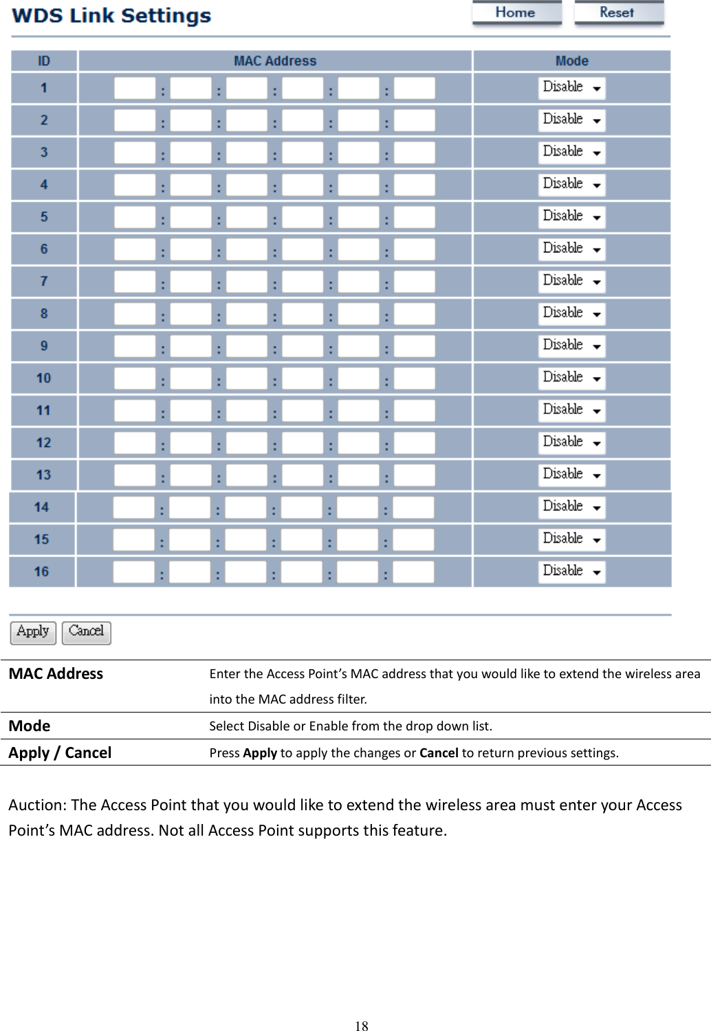
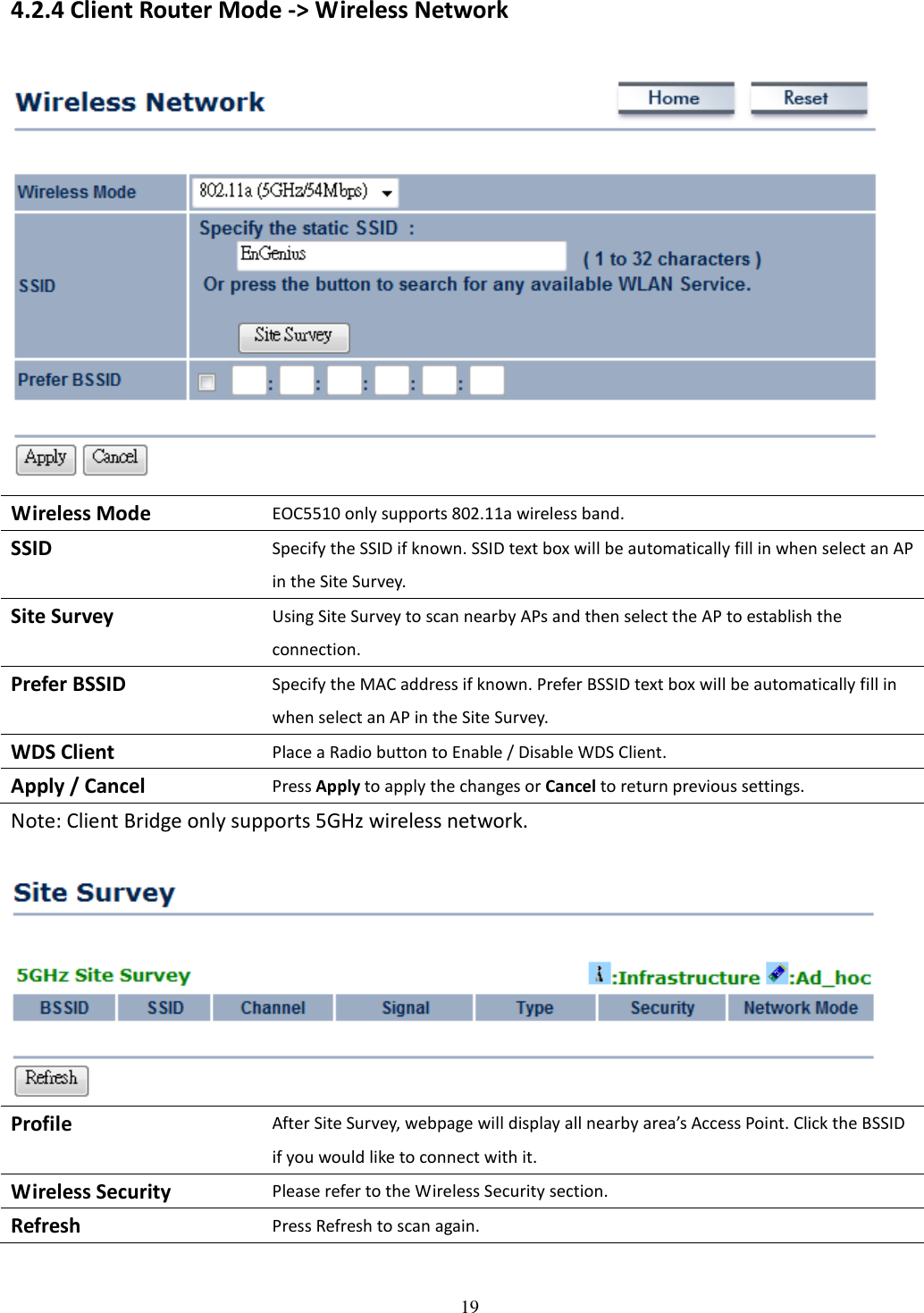
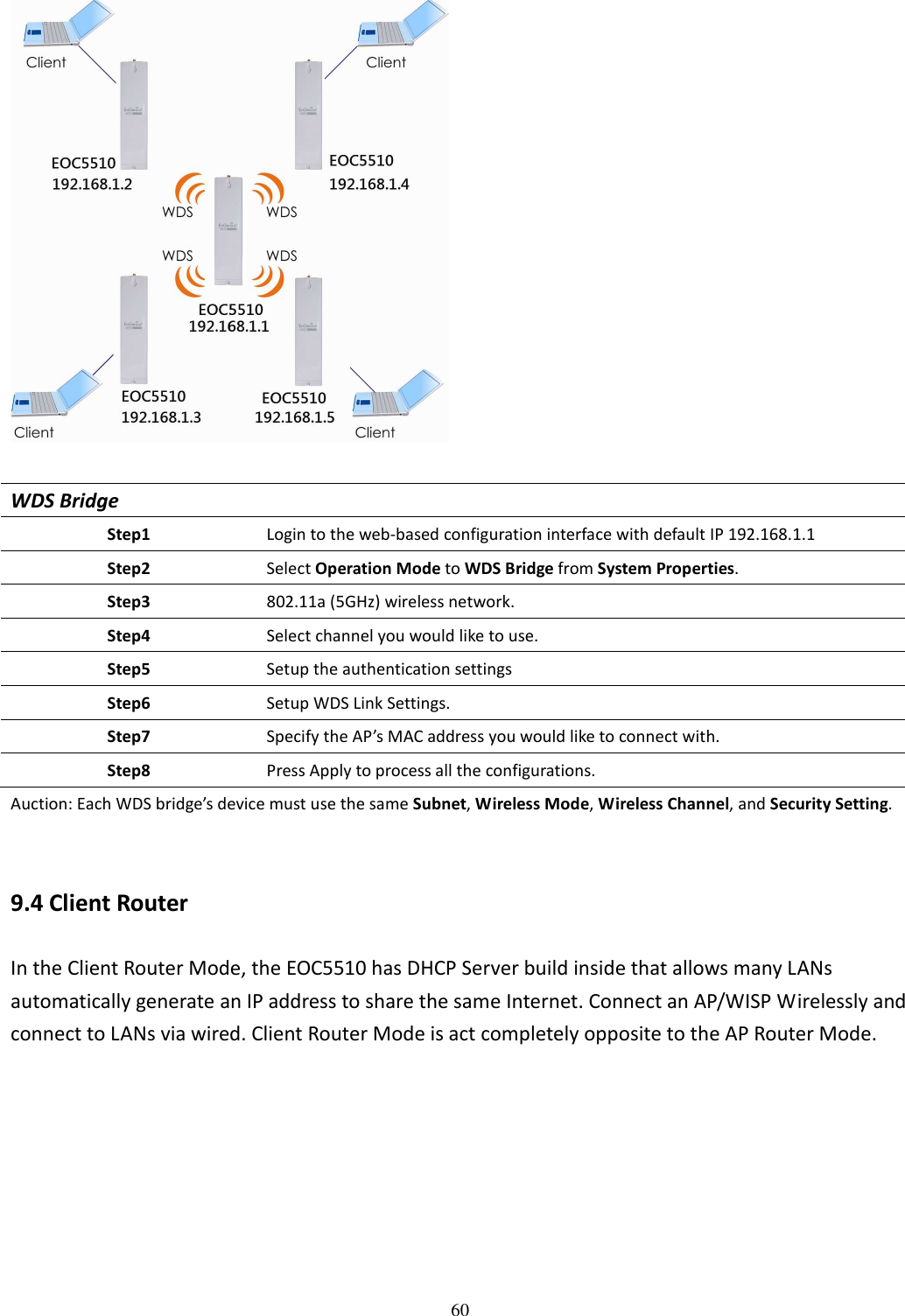
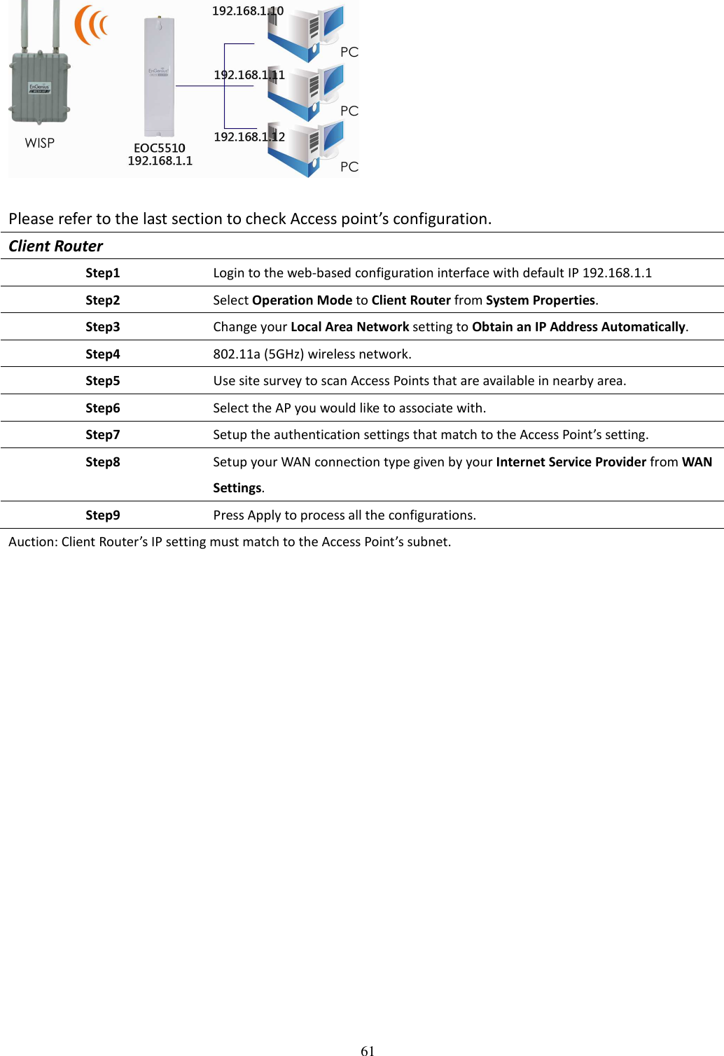
OC5510 User Manual
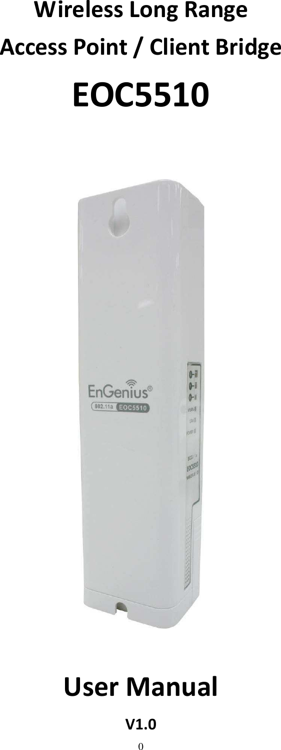
User Manual
Navigation menu
Upload a User Manual
Namespaces
Wiki Guide
HTML
PDF
Info
Views
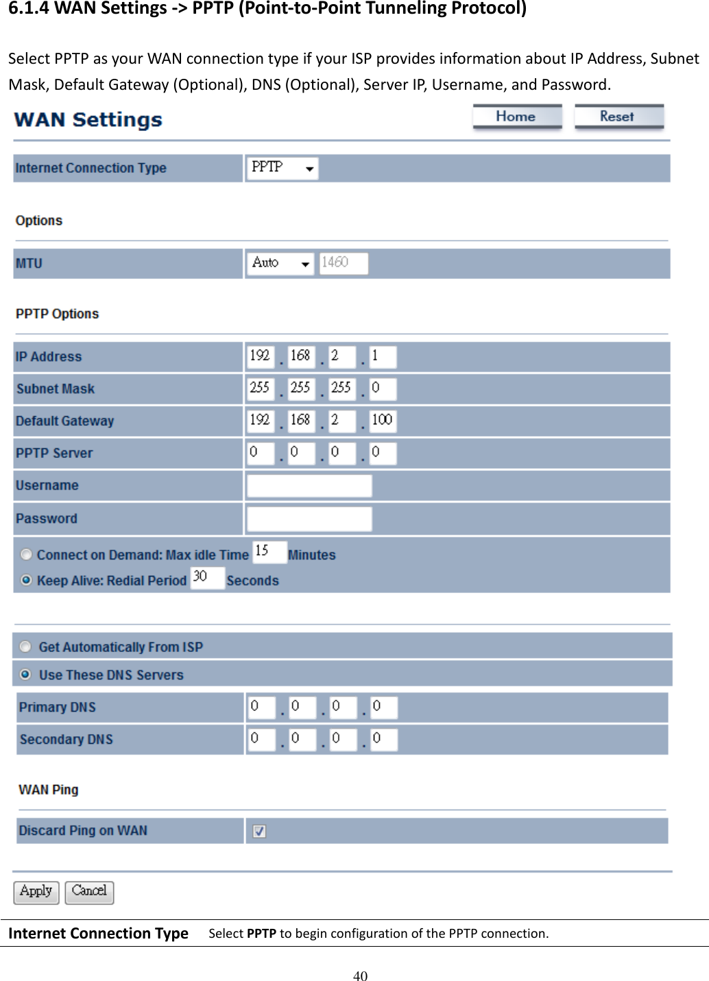
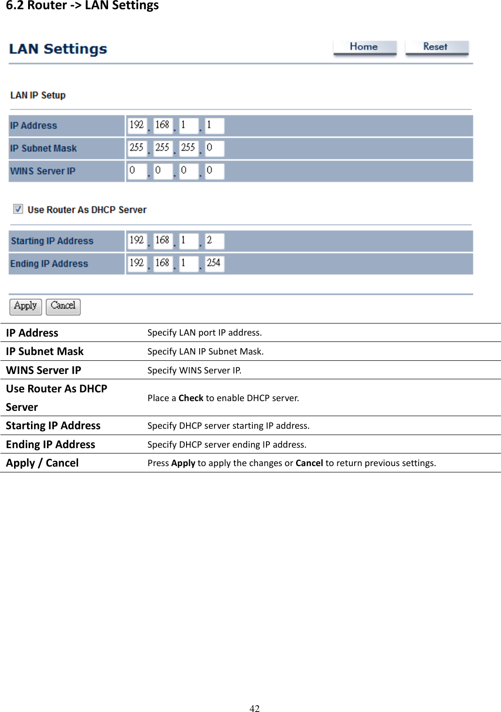
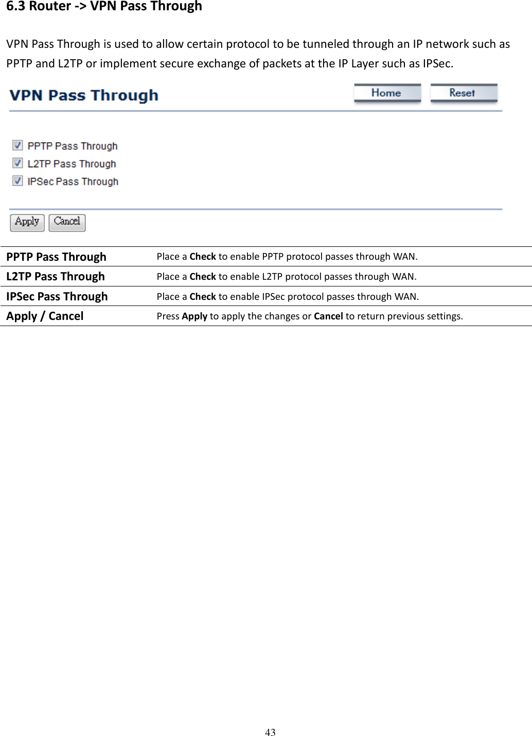
User Manual
Discussion / Help
Navigation