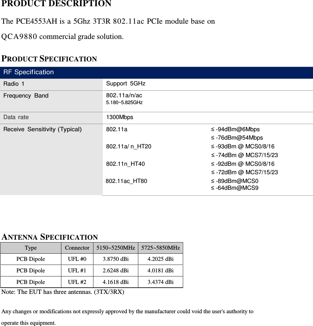
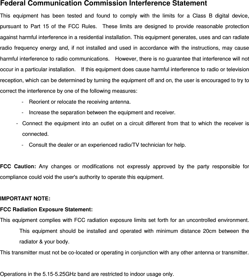
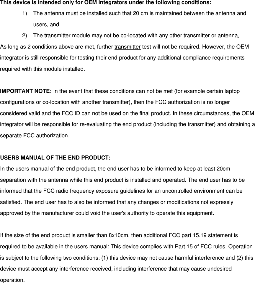
Senao Networks PCE4553AH 802.11 3T3R a/n/ac module User Manual WUG2650 MNL

Senao Networks, Inc. 802.11 3T3R a/n/ac module WUG2650 MNL

User Manual

    802.11 a/n/ac Module   PCE4553AH User’s Manual
PRODUCT DESCRIPTION  The PCE4553AH is a 5Ghz 3T3R 802.11ac PCIe module base on QCA9880 commercial grade solution.  PRODUCT SPECIFICATION  RF Specification Radio 1 Support 5GHz Frequency Band 802.11a/n/ac 5.180~5.825GHz Data rate 1300Mbps Receive Sensitivity (Typical) 802.11a  ≤ -94dBm@6Mbps  ≤ -76dBm@54Mbps 802.11a/ n_HT20 ≤ -93dBm @ MCS0/8/16 ≤ -74dBm @ MCS7/15/23 802.11n_HT40 ≤ -92dBm @ MCS0/8/16 ≤ -72dBm @ MCS7/15/23 802.11ac_HT80 ≤ -89dBm@MCS0  ≤ -64dBm@MCS9    ANTENNA SPECIFICATION Type Connector 5150~5250MHz 5725~5850MHz PCB Dipole UFL #0 3.8750 dBi 4.2025 dBi PCB Dipole UFL #1 2.6248 dBi 4.0181 dBi PCB Dipole UFL #2 4.1618 dBi 3.4374 dBi Note: The EUT has three antennas. (3TX/3RX)  Any changes or modifications not expressly approved by the manufacturer could void the user's authority to operate this equipment.
Federal Communication Commission Interference Statement This equipment has been tested and found to comply with the limits for a Class B digital device, pursuant to Part 15 of the FCC Rules.  These limits are designed to provide reasonable protection against harmful interference in a residential installation. This equipment generates, uses and can radiate radio frequency energy and, if not installed and used in accordance with the instructions, may cause harmful interference to radio communications.    However, there is no guarantee that interference will not occur in a particular installation.    If this equipment does cause harmful interference to radio or television reception, which can be determined by turning the equipment off and on, the user is encouraged to try to correct the interference by one of the following measures: -  Reorient or relocate the receiving antenna. -  Increase the separation between the equipment and receiver. -  Connect the equipment into an outlet on a circuit different from that to which the receiver is connected. -  Consult the dealer or an experienced radio/TV technician for help.  FCC Caution: Any changes or modifications not expressly approved by the party responsible for compliance could void the user's authority to operate this equipment.  IMPORTANT NOTE: FCC Radiation Exposure Statement: This equipment complies with FCC radiation exposure limits set forth for an uncontrolled environment. This equipment should be installed and operated with minimum distance 20cm between the radiator & your body. This transmitter must not be co-located or operating in conjunction with any other antenna or transmitter.  Operations in the 5.15-5.25GHz band are restricted to indoor usage only.
This device is intended only for OEM integrators under the following conditions: 1) The antenna must be installed such that 20 cm is maintained between the antenna and users, and   2) The transmitter module may not be co-located with any other transmitter or antenna,   As long as 2 conditions above are met, further transmitter test will not be required. However, the OEM integrator is still responsible for testing their end-product for any additional compliance requirements required with this module installed.  IMPORTANT NOTE: In the event that these conditions can not be met (for example certain laptop configurations or co-location with another transmitter), then the FCC authorization is no longer considered valid and the FCC ID can not be used on the final product. In these circumstances, the OEM integrator will be responsible for re-evaluating the end product (including the transmitter) and obtaining a separate FCC authorization.  USERS MANUAL OF THE END PRODUCT: In the users manual of the end product, the end user has to be informed to keep at least 20cm separation with the antenna while this end product is installed and operated. The end user has to be informed that the FCC radio frequency exposure guidelines for an uncontrolled environment can be satisfied. The end user has to also be informed that any changes or modifications not expressly approved by the manufacturer could void the user's authority to operate this equipment.    If the size of the end product is smaller than 8x10cm, then additional FCC part 15.19 statement is required to be available in the users manual: This device complies with Part 15 of FCC rules. Operation is subject to the following two conditions: (1) this device may not cause harmful interference and (2) this device must accept any interference received, including interference that may cause undesired operation.
End Product Labeling The final end product must be labelled in a visible area with the following   "Contains FCC ID: U2M-PCE4553AH"  If the size of the end product is larger than 8x10cm, then the following FCC part 15.19 statement has to also be available on the label: This device complies with Part 15 of FCC rules. Operation is subject to the following two conditions:  (1) this device may not cause harmful interference and (2) this device must accept any interference received, including interference that may cause undesired operation.
Manual Information to the End User The OEM integrator has to be aware not to provide information to the end user regarding how to install or remove this RF module in the user’s manual of the end product which integrates this module.   The end user manual shall include all required regulatory information/warning as show in this manual.
Configuration The Wireless Adapter can be configured by Wireless Client Utility (WCU). This chapter describes how to configure your Wireless Adapter for wireless connectivity on your Wireless Local Area Network (WLAN) and use the data security encryption features. After Installing the Adapter, the Adapter’s tray icon   will appear in your system tray. It appears at the bottom of the screen, and shows the signal strength using color and the received signal strength indication (RSSI).   If the icon is gray, there is no connection.  If the icon is red, there is poor signal strength and the RSSI is less than 5dB.  If the icon is yellow, there is poor signal strength and the RSSI is between 5dB and 10dB.  If the icon is green, there is good signal strength and the RSSI is between 10dB and 20dB.  If the icon is green, there is excellent signal strength and the RSSI is more than 20dB. Double-click the icon and the WCU utility will run. You can also run the utility by clicking the Start>Program>Wireless>Wireless Client Utility. The WCU utility provides a complete and easy to use set of tools to:  Display current status information  Edit and add configuration profiles  Display current diagnostics information The section below introduces these above capabilities. Current Status The Current Status tab contains general information about the program and its operations. The Current Status tab does not require any configurations.   The following table describes the items found on the Current Status screen.  Profile Name - The name of current selected configuration profile. Set up the configuration name on the General tab of Profile Management.    Link Status - Shows whether the station is associated to the wireless network.
 Wireless Mode - Displays the wireless mode. Configure the wireless mode on the Advanced tab of Profile Management.  Network Type - The type of network and the station currently connected. The options include: • Infrastructure (access point) • Ad Hoc Configure the network type on the Advanced tab of Profile Management.  IP Address - Displays the computer’s IP address.  Current Channel - Shows the currently connected channel.  Data Encryption - Displays the encryption type the driver is using. Configure the encryption type on the Security tab of Profile Management.  Server Based Authentication - Shows whether server based authentication is used.  Signal Strength - Shows the strength of the signal. Note: In the WCU utility, access the General tab, Security tab and Advanced tab by clicking New or Modify on the Profile Management tab. Click Advanced to see advanced information about the program and its operations. For more information, please refer to the help file of the utility.  Profile Management Click the Profile Management tab of the WCU Utility and the Profile Management screen will appear. The Profile Management screen provides tools to:  Add a profile  Edit a profile  Remove a profile  Switch to another Profile  Import a Profile  Export a Profile  Scan Available Networks  Order profiles
 Add or Modify a Configuration Profile To add a new configuration profile, click New on the Profile Management tab. To modify a configuration profile, select the configuration from the Profile list and click Modify. 1. Edit the General tab  Profile Name - Identifies the configuration profile. This name must be unique. Profile names are not case-sensitive.  Client Name - Identifies the client machine.  Network Names (SSIDs) - The IEEE 802.11 wireless network name. This field has a maximum limit of 32 characters.
2. Edit the Security tab Edit the fields in the Security tab of Profile Management to configure the profile. To define the security mode, select the radio button of the desired security mode.    WPA - Wi-Fi Protected Access  WPA Passphrase - Wi-Fi Protected Access Passphrase  802.1x - Enables 802.1x security.  Shared Key (Static WEP) - Enables the use of shared keys that are defined on both the access point and the station. To define shared encryption keys, choose the Shared Key radio button and click Configure to fill in the Define Shared Keys window. None: No security (not recommended). Note: If the access point that the wireless adapter is associating to has WEP set to Optional and the client has WEP enabled, make sure that Allow Association to Mixed Cells is checked on the Security Tab to allow association. To complete WEP encryption configuration, you must select the 802.11 Authentication Mode as appropriate on the Advanced tab of this Profile Management dialog.
 3. Edit the Advanced tab  Transmit Power Level - Selects the transmit power level for in mW. Actual transmit power may be limited by regulatory domain or hardware limitations.  Power Save Mode - • Maximum - Selects maximum mode to let the access point buffer incoming messages for the wireless adapter.   The adapter will detect the access point if any messages are waiting periodically. • Normal  - In Normal mode, the adapter will be switched to maximum mode automatically when no large packets are retrieved. • Off - turns power saving off, thus powering up the wireless adapter continuously for a short message response time.  802.11 Authentication Mode - Select which mode the wireless adapter uses to authenticate to an access point: • Automatic causes the adapter to attempt authentication using shared, but switches it to open authentication if shared fails. • Open System enables an adapter to attempt authentication regardless of its WEP settings. It will only associate with the access point if the WEP keys on both the adapter and the access point match. • Shared-key only allows the adapter to associate with access points that have the same WEP key. For infrastructure (access point) networks, click Preferred APs… to specify up to four access points to the client adapter that attempts to be associated to the access points.
Scan Available Networks 1. Click Scan on the Profile Management, the Available Infrastructure and Ad Hoc Networks window will appear. 2. Click Refresh to refresh the list at any time. 3. Highlight a network name and click Activate to connect an available network. If no configuration profile exists for that network, the Profile Management window will open the General tab. Fill in the Profile name and click OK to create the configuration profile for that network.  Auto Profile Selection Management The auto selection feature allows the wireless adapter to automatically select a profile from the list of profiles and use it to connect to the network. To add a new profile into the Auto Selected Profiles list, please follow these steps. 1. On the Profile Management tab, click Order Profiles…. 2. The Auto Profiles Selection management window will appear, with a list of all created profiles in the Available Profiles box. 3. Highlight the profiles to add to auto profile selection, and click Add. The profile will appear in the Auto Selected Profiles box. 4. Highlight a profile in the Auto Selected Profiles box. 5. Click Move Up or Move Down as appropriate. Note: The first profile in the Auto Selected Profiles box has highest priority, and the last profile has lowest priority. 6. Click OK. 7. Check the Auto Select Profiles checkbox on the Profile Management tab. Note: When auto profile selection is enabled by checking Auto Select Profiles on the Profile Management tab, the client adapter will scan for an available network. The profile with the highest priority and the same SSID as one of the found networks will be used to connect to the network. If the connection fails, the client adapter will try the next highest priority profile that matches the SSID until an available network is found.

Navigation menu