Senao Networks RB9260 300Mbps Wireless N Range Extender User Manual ECB 9750
Senao Networks, Inc. 300Mbps Wireless N Range Extender ECB 9750
UserManual.wiki
>
Senao Networks
>
RB9260 User Manual
UserMan_U2M-RB9260_R1
Navigation menu
Upload a User Manual
Namespaces
Wiki Guide
HTML
PDF
Info
Views
User Manual
Discussion / Help
Navigation

![9 Windows XP, click [Network Connection] Windows Vista, click [View Network Status and Tasks] then [Manage Network Connections] Windows 7, click [View Network Status and Tasks] then [Change adapter settings]](https://usermanual.wiki/Senao-Networks/RB9260/User-Guide-1713496-Page-10.png)
![10 Right click on [Local Area Connection] and select [Properties]. Check “Client for Microsoft Networks”, “File and Printer Sharing for Microsoft Networks”, and “Internet Protocol (TCP/IP)” is ticked. If not, please install them.](https://usermanual.wiki/Senao-Networks/RB9260/User-Guide-1713496-Page-11.png)
![11 Select “Internet Protocol (TCP/IP)” and click [Properties] Select “Obtain an IP Address automatically” and “Obtain DNS server address automatically” then click [OK].](https://usermanual.wiki/Senao-Networks/RB9260/User-Guide-1713496-Page-12.png)
![19 7.2 One-Touch Setup (WPS) 1. Click [WPS] button on ERB9260](https://usermanual.wiki/Senao-Networks/RB9260/User-Guide-1713496-Page-20.png)
![20 2. Click [WPS] button on the Access Point. Note: It may take up to 60 seconds for ERB9260 to clone the AP. Please wait until WPS led stops blinking and stay ON. If the connection is successful. There will be TWO HomeAP in the environment.](https://usermanual.wiki/Senao-Networks/RB9260/User-Guide-1713496-Page-21.png)
![34 8.6 Monitor This page shows a histogram of the Ethernet and Wireless LAN traffic. Click on [Detail] to get the detail information.](https://usermanual.wiki/Senao-Networks/RB9260/User-Guide-1713496-Page-35.png)
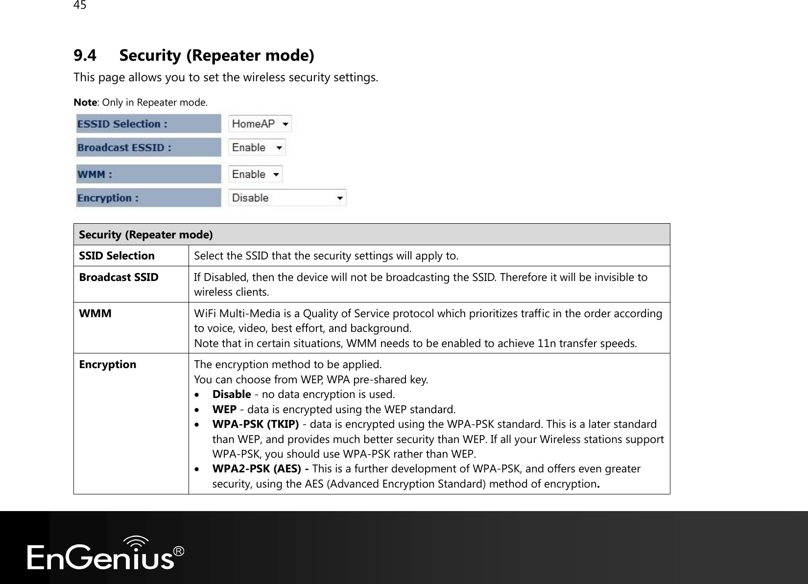
![37 9.2 Basic This page shows the current status of the device’s Wireless settings. Repeater mode: Basic (Repeater mode) Radio Enable or Disable the device’s wireless signal. Band Select the types of wireless clients that the device will accept. eg: 2.4 Ghz (B+G) Only 802.11b and 11g clients will be allowed. ESSID1 Enter the name of your wireless network. You can use up to 32 characters. Site Survey Click on [Site Survey] to search the existing AP.](https://usermanual.wiki/Senao-Networks/RB9260/User-Guide-1713496-Page-38.png)
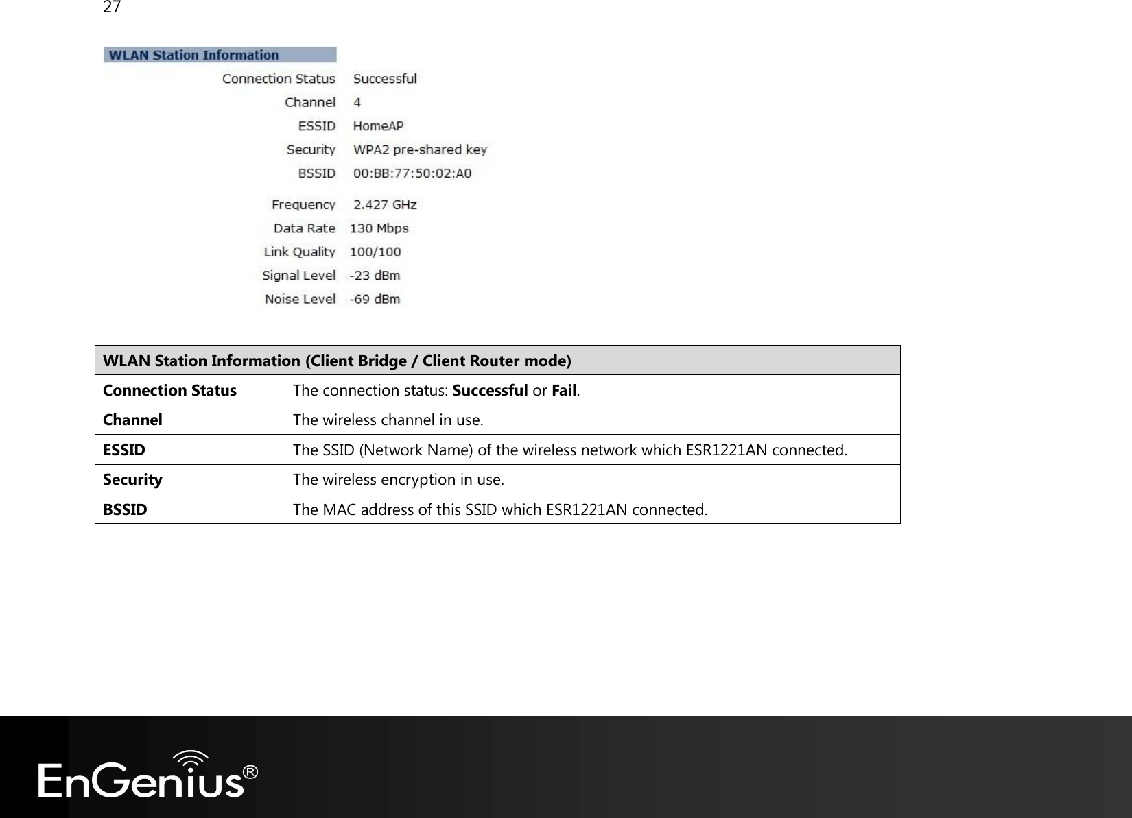
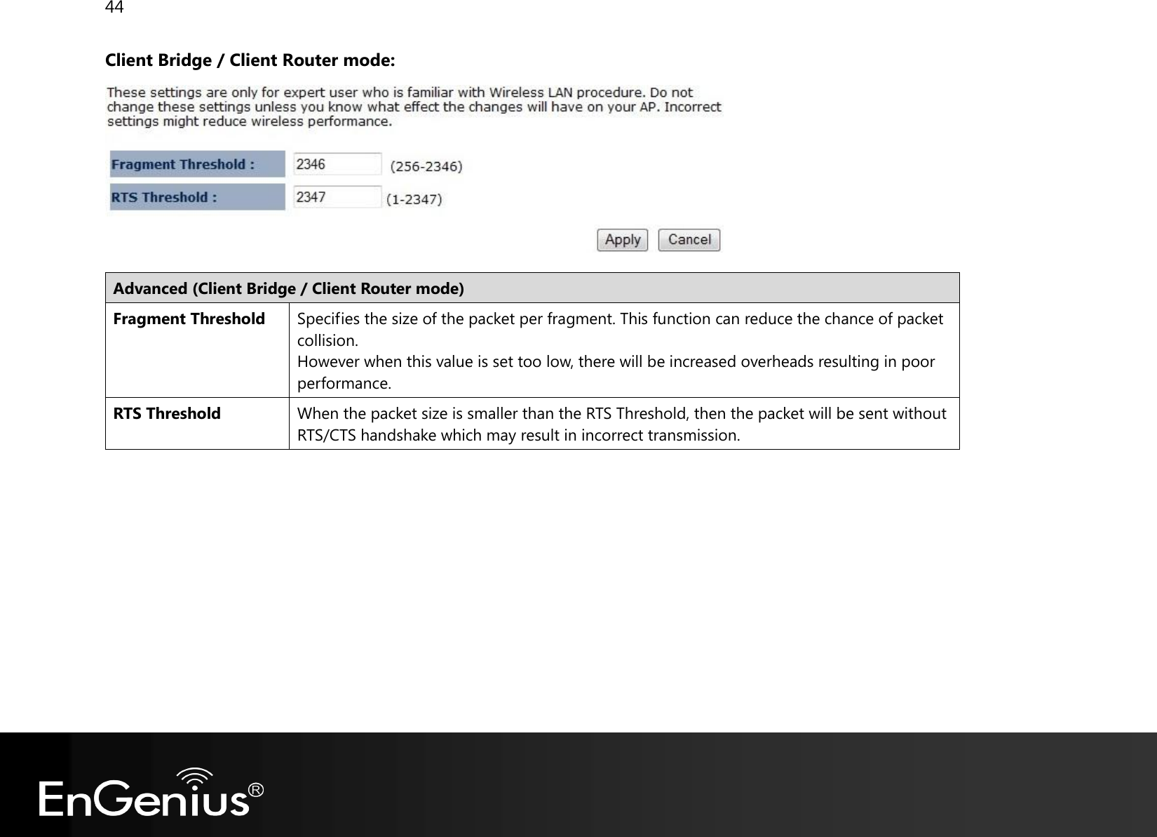
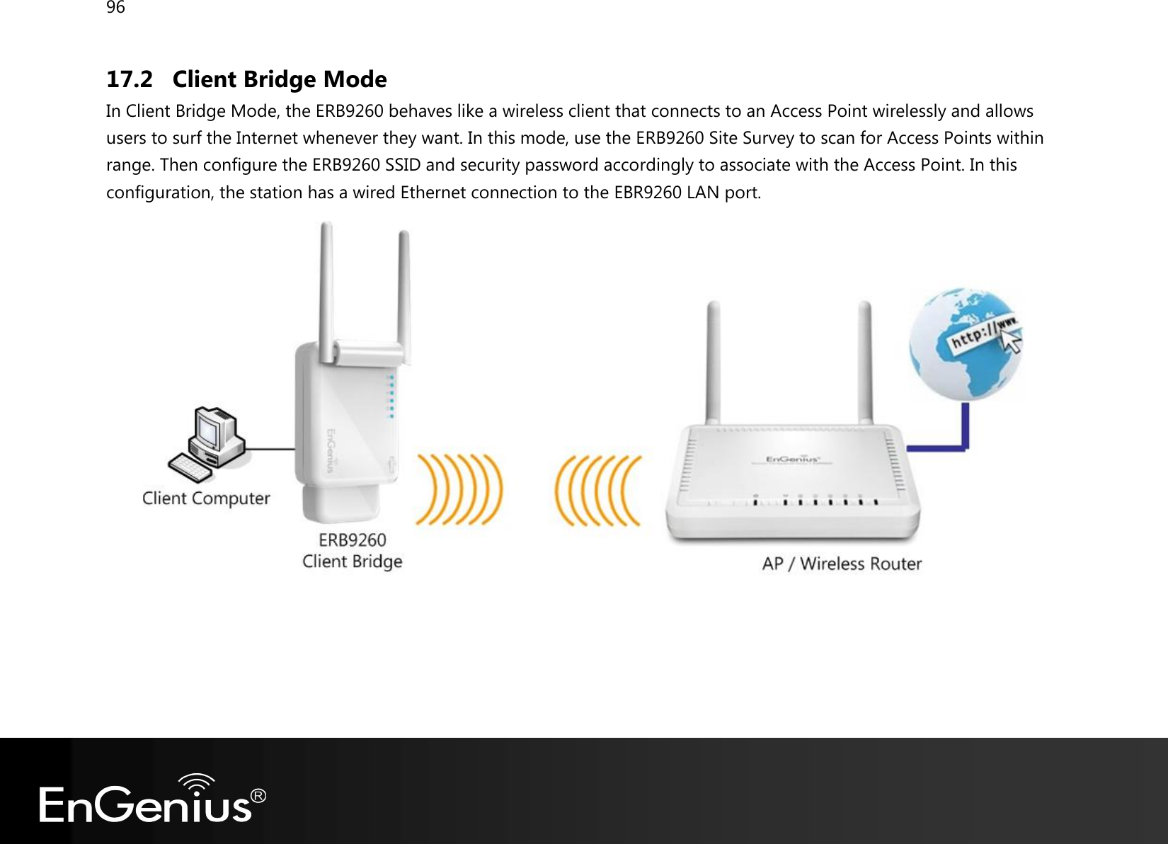
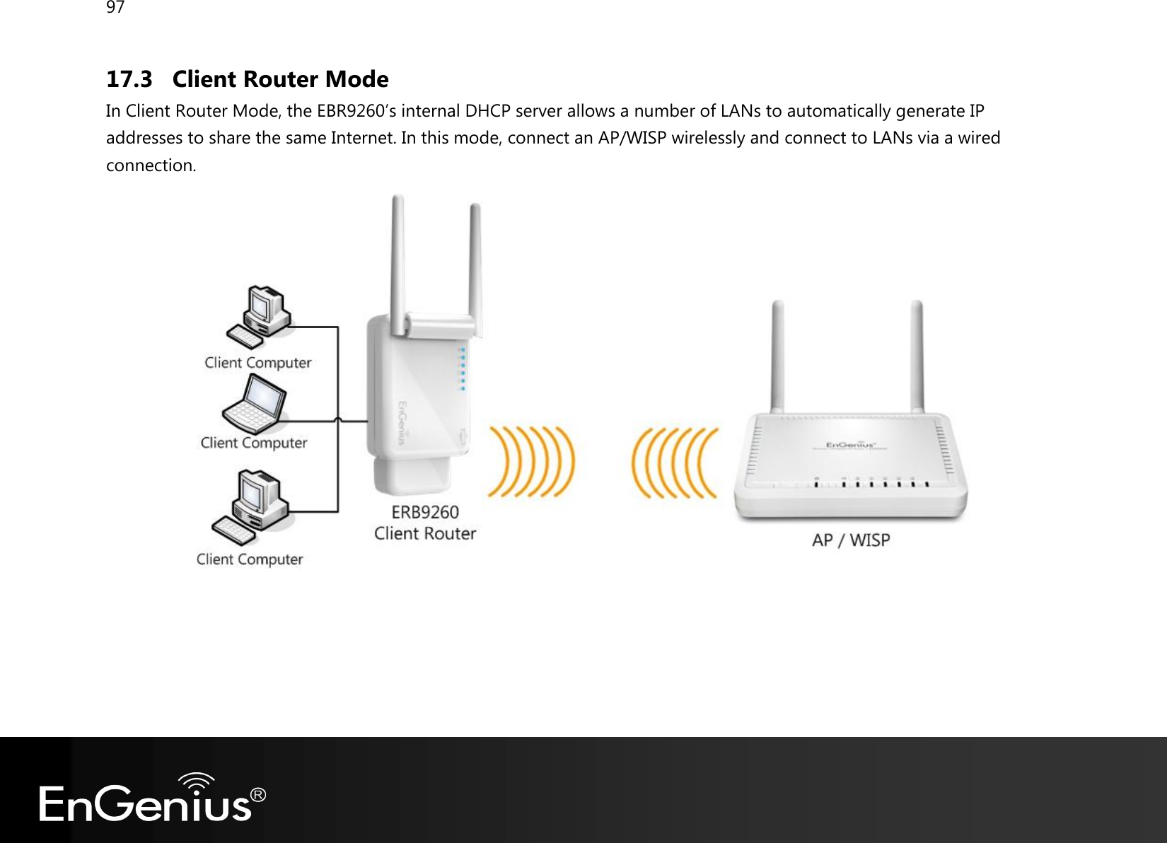
![38 Client Bridge / Client Router mode: Basic (Client Bridge / Client Router mode) Radio Enable or Disable the device’s wireless signal. Band Select the types of wireless clients that the device will accept. Site Survey Click on [Site Survey] to search the existing AP.](https://usermanual.wiki/Senao-Networks/RB9260/User-Guide-1713496-Page-39.png)
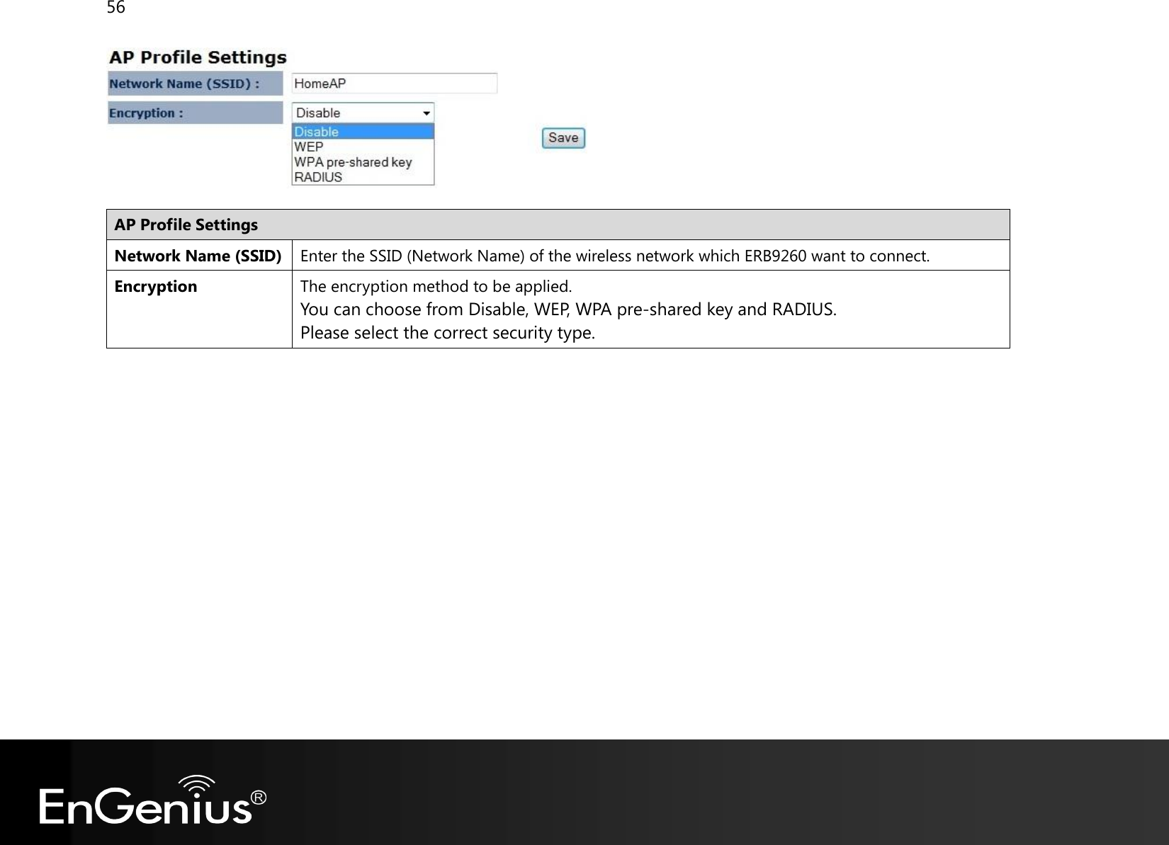
![40 2. Select an AP and click on [Add to AP Profile]. 3. Enter the correct security setting.](https://usermanual.wiki/Senao-Networks/RB9260/User-Guide-1713496-Page-41.png)
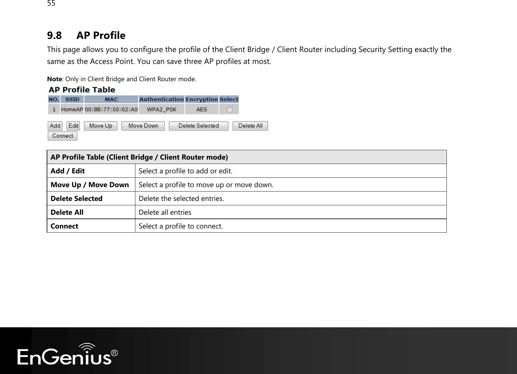
![41 4. Add AP profile successfully, click on [Close] to close the browser. 5. The AP profile is added in AP Profile Table.](https://usermanual.wiki/Senao-Networks/RB9260/User-Guide-1713496-Page-42.png)
![51 Step 1: Click [WPS] button on ERB9260.](https://usermanual.wiki/Senao-Networks/RB9260/User-Guide-1713496-Page-52.png)
![52 Step 2: Click [WPS] button on the Access Point Note: It may take up to 60 seconds for ERB9260 to clone the AP. Please wait until WPS led stops blinking and stay ON. If the connection is successful, there will be TWO HomeAP in the environment.](https://usermanual.wiki/Senao-Networks/RB9260/User-Guide-1713496-Page-53.png)
![54 9.7 Client List (Repeater mode) This page shows the wireless clients that are connected to the device. Click on [Refresh] to get the latest user list and information update. Note: Only in Repeater mode.](https://usermanual.wiki/Senao-Networks/RB9260/User-Guide-1713496-Page-55.png)
![85 13.2 Firmware This page allows you to upgrade the device's firmware. To perform the Firmware Upgrade: 1. Click the [Browse] button and navigate to the location of the upgrade file. 2. Select the upgrade file. Its name will appear in the Upgrade File field. 3. Click the [Apply] button to commence the firmware upgrade. Note: The device is unavailable during the upgrade process, and must restart when the upgrade is completed. Any connections to or through the device will be lost.](https://usermanual.wiki/Senao-Networks/RB9260/User-Guide-1713496-Page-86.png)
![86 Emergency Upgrade If you upgrade fail, you may enter Emergency Upgrade WEB page. 1. Enter IP address: 192.168.1.2 and enter Emergency Upgrade WEB page. 2. Select [LOGIN] to enter firmware upgrade WEB page. 3. Click the [Browse] button and navigate to the location of the upgrade file and then click [UPLOAD].](https://usermanual.wiki/Senao-Networks/RB9260/User-Guide-1713496-Page-87.png)
![88 13.3 Configure This page allows you to save the current device configurations. When you save the configurations, you also can re-load the saved configurations into the device through the [Restore Settings]. If extreme problems occur you can use the [Restore to Factory Defaults] to set all configurations to its original default settings. Configure Restore to Factory Default Restores the device to factory default settings. Backup Settings Save the current configuration settings to a file. Restore Settings Restores a previously saved configuration file. Click Browse to select the file. Then Upload to load the settings.](https://usermanual.wiki/Senao-Networks/RB9260/User-Guide-1713496-Page-89.png)
![89 13.4 Reset In some circumstances it may be required to force the device to reboot. Click on [Apply] to reboot.](https://usermanual.wiki/Senao-Networks/RB9260/User-Guide-1713496-Page-90.png)
![94 16 Logout Click on [Logout] button to logout.](https://usermanual.wiki/Senao-Networks/RB9260/User-Guide-1713496-Page-95.png)
![99 Appendix B – Industry Canada statement Industry Canada statement: This device complies with RSS-210 of the Industry Canada Rules. Operation is subject to the following two conditions: (1) This device may not cause harmful interference, and (2) this device must accept any interference received, including interference that may cause undesired operation. Ce dispositif est conforme à la norme CNR-210 d'Industrie Canada applicable aux appareils radio exempts de licence. Son fonctionnement est sujet aux deux conditions suivantes: (1) le dispositif ne doit pas produire de brouillage préjudiciable, et (2) ce dispositif doit accepter tout brouillage reçu, y compris un brouillage susceptible de provoquer un fonctionnement indésirable. IMPORTANT NOTE: Radiation Exposure Statement: This equipment complies with IC radiation exposure limits set forth for an uncontrolled environment. This equipment should be installed and operated with minimum distance 20cm between the radiator & your body. NOTE IMPORTANTE: Déclaration d'exposition aux radiations: Cet équipement est conforme aux limites d'exposition aux rayonnements IC établies pour un environnement non contrôlé. Cet équipement doit être installé et utilisé avec un minimum de 20 cm de distance entre la source de rayonnement et votre corps. This device has been designed to operate with a dipole antenna have a maximum gain of [2] dB. Antenna having a higher gain is strictly prohibited per regulations of Industry Canada. The required antenna impedance is 50 ohms. Under Industry Canada regulations, this radio transmitter may only operate using an antenna of a type and maximum (or lesser) gain approved for the transmitter by Industry Canada. To reduce potential radio interference to other users, the antenna type and its gain should be so chosen that the equivalent isotropically radiated power (e.i.r.p.) is not more than](https://usermanual.wiki/Senao-Networks/RB9260/User-Guide-1713496-Page-100.png)
![100 that necessary for successful communication. This radio transmitter (IC: 3616C-RB9260 / Model: ERB9260) has been approved by Industry Canada to operate with the antenna type, maximum permissible gain and required antenna impedance for each antenna type indicated. Antenna types not included in this user’s manual, having a gain greater than the maximum gain indicated for that type, are strictly prohibited for use with this device. Ce dispositif a été conçu pour fonctionner avec une antenne ayant un gain maximal de diople antenne avec dB [2]. Une antenne à gain plus élevé est strictement interdite par les règlements d'Industrie Canada. L'impédance d'antenne requise est de 50 ohms. Conformément à la réglementation d'Industrie Canada, le présent émetteur radio peutfonctionner avec une antenne d'un type et d'un gain maximal (ou inférieur) approuvé pourl'émetteur par Industrie Canada. Dans le but de réduire les risques de brouillage radioélectriqueà l'intention des autres utilisateurs, il faut choisir le type d'antenne et son gain de sorte que lapuissance isotrope rayonnée équivalente (p.i.r.e.) ne dépasse pas l'intensité nécessaire àl'établissement d'une communication satisfaisante. Le présent émetteur radio (IC: 3616C-RB9260 / Model: ERB9260) a été approuvé par Industrie Canada pour fonctionner avec les types d'antenne énumérés ci-dessous et ayant un gain admissible maximal et l'impédance requise pour chaque type d'antenne. Les types d'antenne non inclus dans cette liste, ou dont le gain est supérieur au gain maximal indiqué, sont strictement interdits pour l'exploitation de l'émetteur.](https://usermanual.wiki/Senao-Networks/RB9260/User-Guide-1713496-Page-101.png)