Senao Networks SR1221N10 Wireless 11N Router User Manual
Senao Networks, Inc. Wireless 11N Router
UserManual.wiki
>
Senao Networks
>
SR1221N10 User Manual
User Manual
Navigation menu
Upload a User Manual
Namespaces
Wiki Guide
HTML
PDF
Info
Views
User Manual
Discussion / Help
Navigation
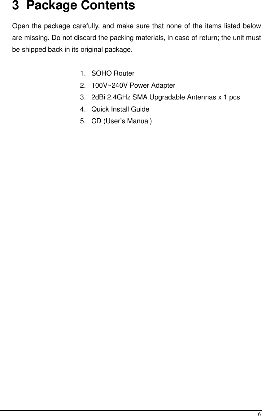
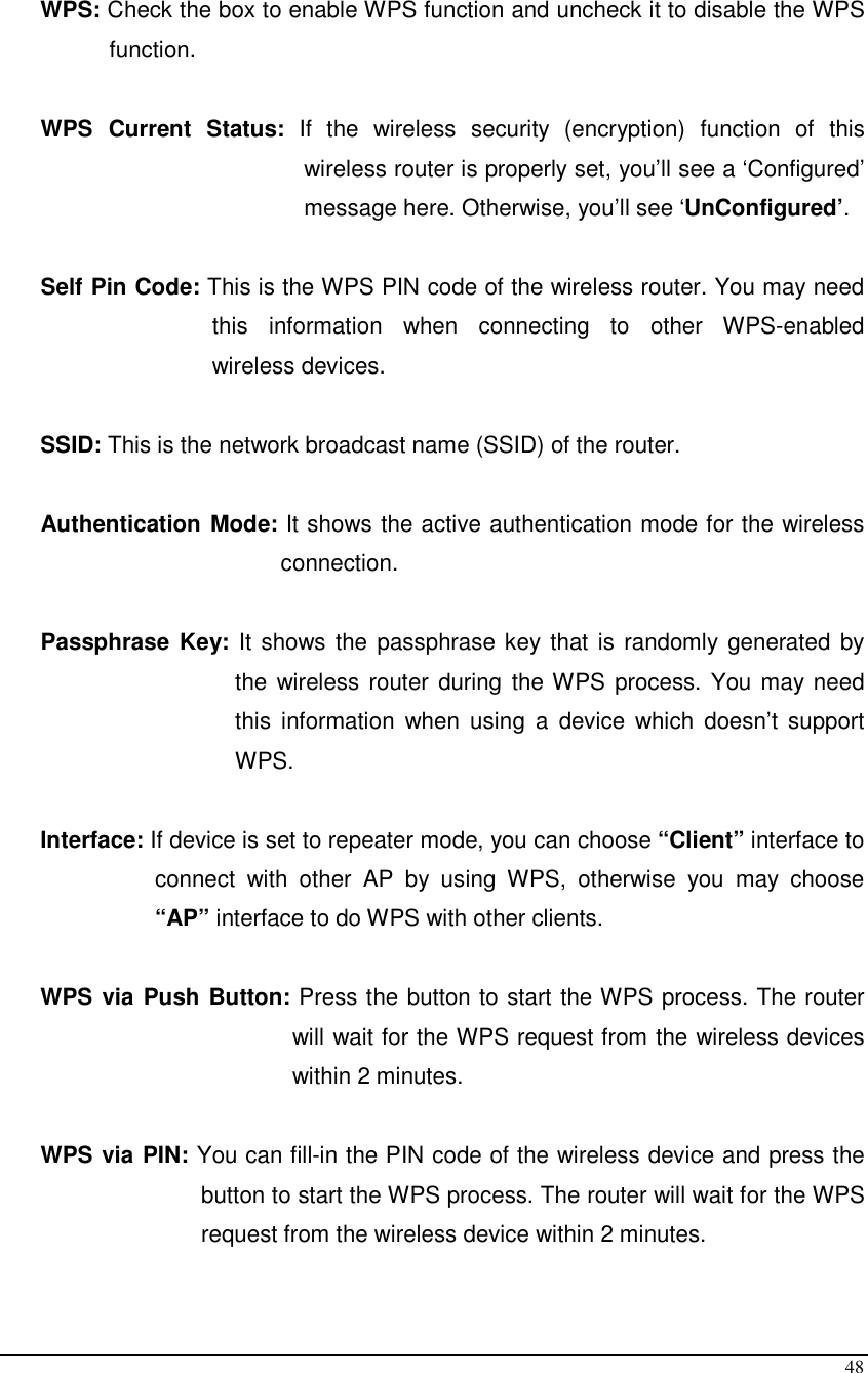
![12 8 PC Network Adapter setup (Windows XP) • Enter [Start Menu] select [Control panel] select [Network]. • Select [Local Area Connection]) icon=>select [properties]](https://usermanual.wiki/Senao-Networks/SR1221N10/User-Guide-1349509-Page-12.png)
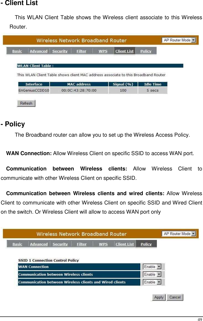
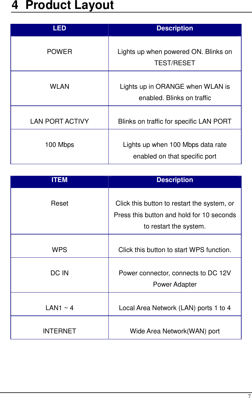
![13 • Select [Internet Protocol (TCP/IP)] =>Click [Properties]. • Select the [General] tab. a. ESR1221N supports [DHCP] function, please select both [Obtain an IP address automatically] and [Obtain DNS server address automatically].](https://usermanual.wiki/Senao-Networks/SR1221N10/User-Guide-1349509-Page-13.png)
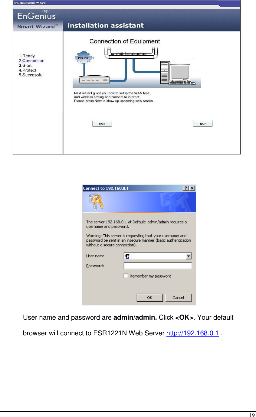
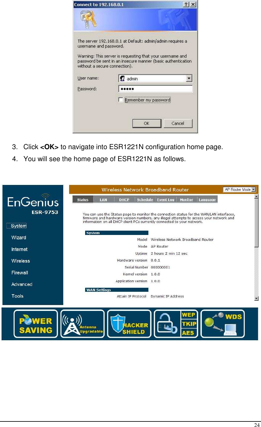
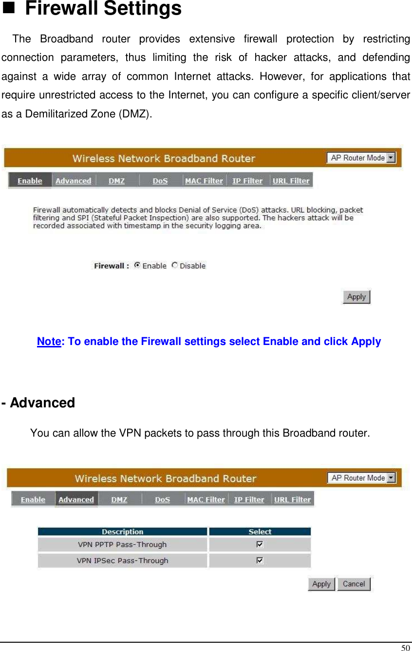
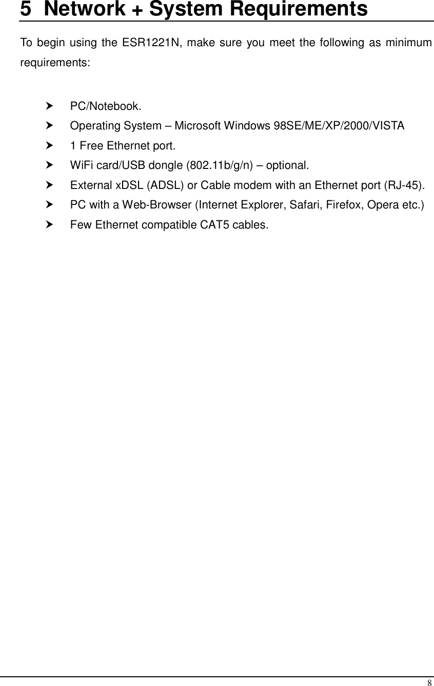
![23 11 Initial Setup ESR1221N ESR1221N uses web-interface for configuration to be accessed through your web browser, such as Internet Explorer or Firefox. - LOGIN Procedure 1. OPEN your browser (e.g. Internet Explorer). 2. Type http://192.168.0.1 in address bar and hit [Enter] button on your keyboard.](https://usermanual.wiki/Senao-Networks/SR1221N10/User-Guide-1349509-Page-23.png)