Senao Networks SR7260 Wireless concurrent dual band Gigabit Router 300N User Manual WBR 5050 UM 080911 for ADT
Senao Networks, Inc. Wireless concurrent dual band Gigabit Router 300N WBR 5050 UM 080911 for ADT
UserManual.wiki
>
Senao Networks
>
SR7260 User Manual
UserMan_U2M-SR7260
Navigation menu
Upload a User Manual
Namespaces
Wiki Guide
HTML
PDF
Info
Views
User Manual
Discussion / Help
Navigation
![12 • Windows XP, click [Network Connection] • Right click on [Local Area Connection] and select [Properties]. • Windows Vista, click [View Network Status and Tasks] then [Manage Network Connections]](https://usermanual.wiki/Senao-Networks/SR7260/User-Guide-1524617-Page-12.png)
![13 • Make sure the boxes “Client for Microsoft Networks”, “File and Printer Sharing”, and “Internet Protocol (TCP/IP)” are checked. If not, please install them. • Select Obtain an IP Address automatically and Obtain DNS server address automatically • Click OK to complete • Select “Internet Protocol (TCP/IP)” and click [Properties]](https://usermanual.wiki/Senao-Networks/SR7260/User-Guide-1524617-Page-13.png)
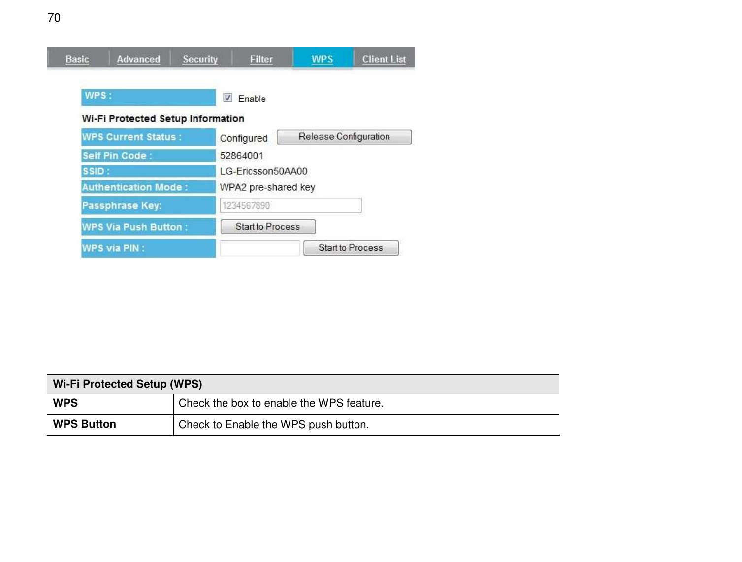
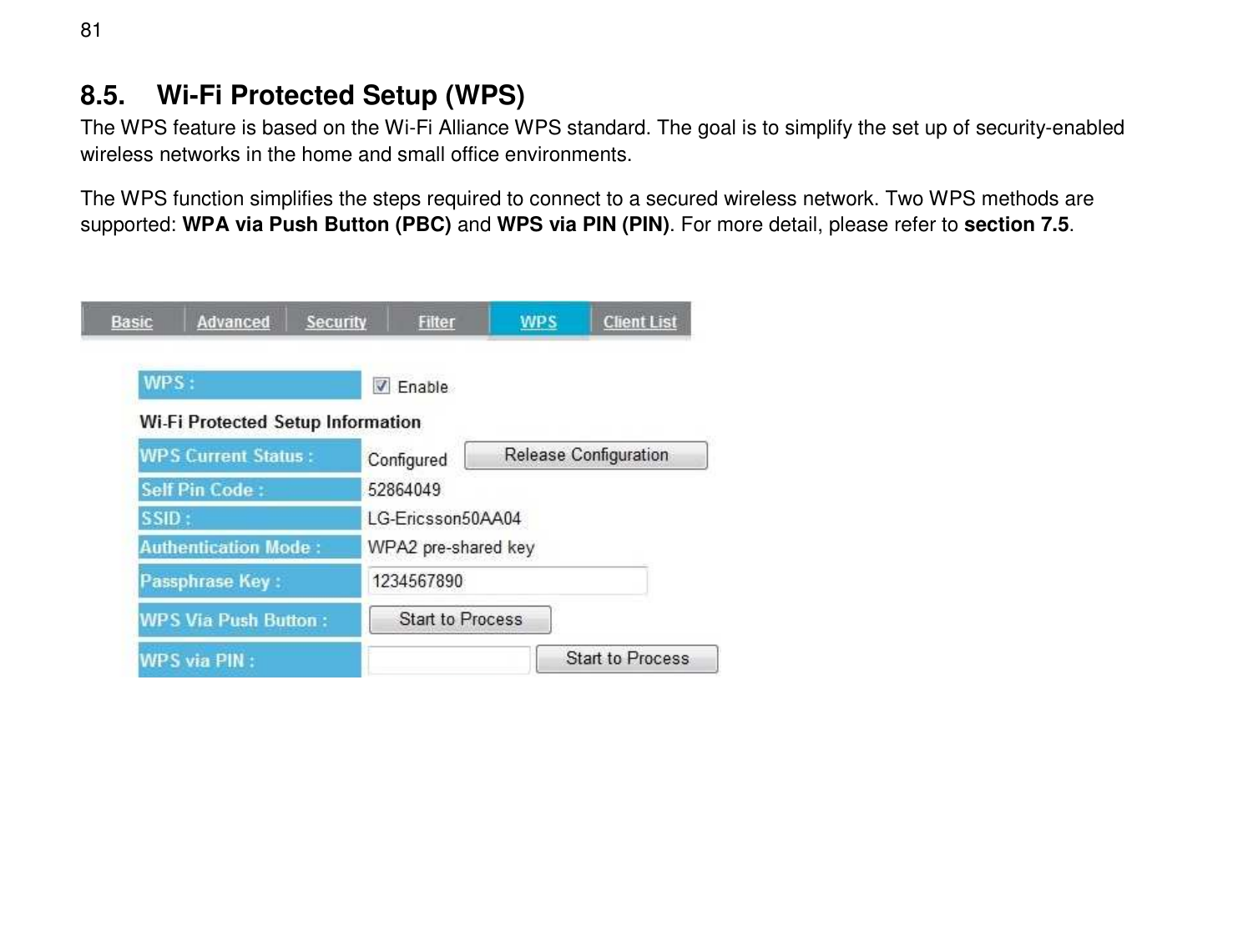
![71 Wi-Fi Protected Setup Information WPS Current Status Shows whether the WPS function is Configured or Unconfigured. Configured means that WPS has been used to authorize connection between the device and wireless clients. SSID The SSID (name of the wireless network) used when connecting using WPS. Authentication Mode The encryption method used by the WPS process. Passphrase Key This is the passphrase key that is randomly generated during the WPS process. It is required if wireless clients that do not support WPS attempt to connect to the wireless network. WPS Via Push Button Click this button to initialize the WPS feature using the push button method. WPS Via PIN Enter the PIN code from wireless adapter and then click [Start to Process] button to initialize the WPS feature. There are two methods to initialize the WPS feature: WPS via Push Button (PBC) and WPS via Pin (PIN). 1. Push Button Method (PBC – Push Button Connect) Press the WPS button on your wireless adapter and press the WPS button on the top panel of the Router to establish the connection.](https://usermanual.wiki/Senao-Networks/SR7260/User-Guide-1524617-Page-71.png)
![72 – Or – a. Log into the browser utility of the Router (see “Manually enter Setup Wizard” in section 4). b. Click the Wireless tab on the left menu, and then click the WPS tab on the top menu. c. Next to “WPS Via Push Button”, click Start to Process to establish the connection. 2. Pin Code Method (PIN) Enter the PIN code of wireless adapter in WPS Via PIN field and then click [Start to Process] button to initialize the WPS process. Note that this process may be different for each brand/model. Refer to the user manual of your wireless client adapter for more information.](https://usermanual.wiki/Senao-Networks/SR7260/User-Guide-1524617-Page-72.png)