Senao Networks SR7750 802.11 abgn Dual Band Concurrent Router User Manual ESR7750 for Certificatoin 20090618
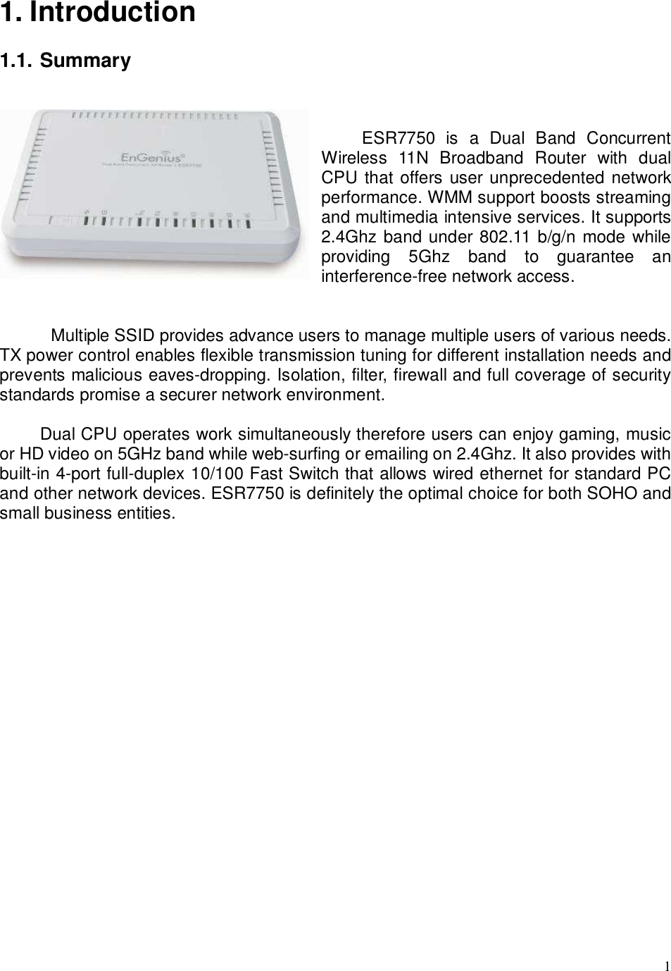
Senao Networks, Inc. 802.11 abgn Dual Band Concurrent Router ESR7750 for Certificatoin 20090618
UserManual.wiki
>
Senao Networks
>
SR7750 User Manual
Manual
Navigation menu
Upload a User Manual
Namespaces
Wiki Guide
HTML
PDF
Info
Views
User Manual
Discussion / Help
Navigation

![8 2.4. PC Network Adapter setup (Windows XP) Enter [Start Menu] select [Control panel] select [Network]. Select [Local Area Connection]) icon=>select [properties]](https://usermanual.wiki/Senao-Networks/SR7750/User-Guide-1127523-Page-12.png)
![9 Select [Internet Protocol (TCP/IP)] =>Click [Properties]. Select the [General] tab. select both [Obtain an IP address automatically] and [Obtain DNS server address automatically].](https://usermanual.wiki/Senao-Networks/SR7750/User-Guide-1127523-Page-13.png)
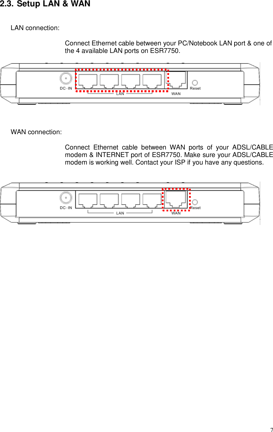
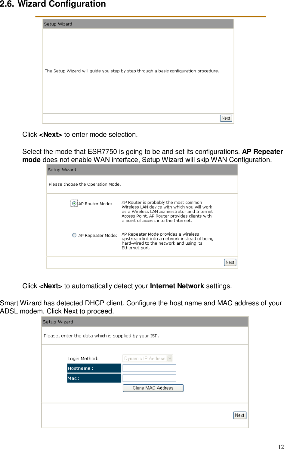
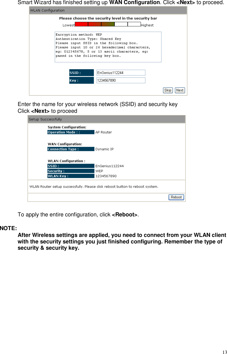
![10 2.5. Smart Wizard CD Connect the supplied power-adapter to the power inlet port and connect it to a wall outlet. Then, the router automatically enters the self-test phase. During self-test phase, Power LED will blink briefly, and then will be lit continuously to indicate that this product is in normal operation. Minimum Requirements • A standard CD-ROM drive • ADSL or cable modem should be ready for Internet connection. • Modem must provide RJ45 port to connect with ESR7750. • Microsoft Windows compatible PC/Notebook with UPnP enabled network adapter • CAT 5 network cable(s), RJ45 port on PC/Notebook. STEP 1 Power up the device. Wait for POWER led on front panel lights up & remains stable. STEP 2 Insert Wizard CD into your CD-ROM drive and browse it with Windows Explorer. Click on “Wizard.exe” to activate SMART WIZARD. STEP 3 Click on [Setup Wizard] and follow the instruction given on the screen to complete the initial device configuration.](https://usermanual.wiki/Senao-Networks/SR7750/User-Guide-1127523-Page-14.png)

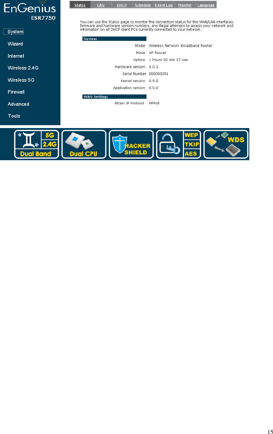
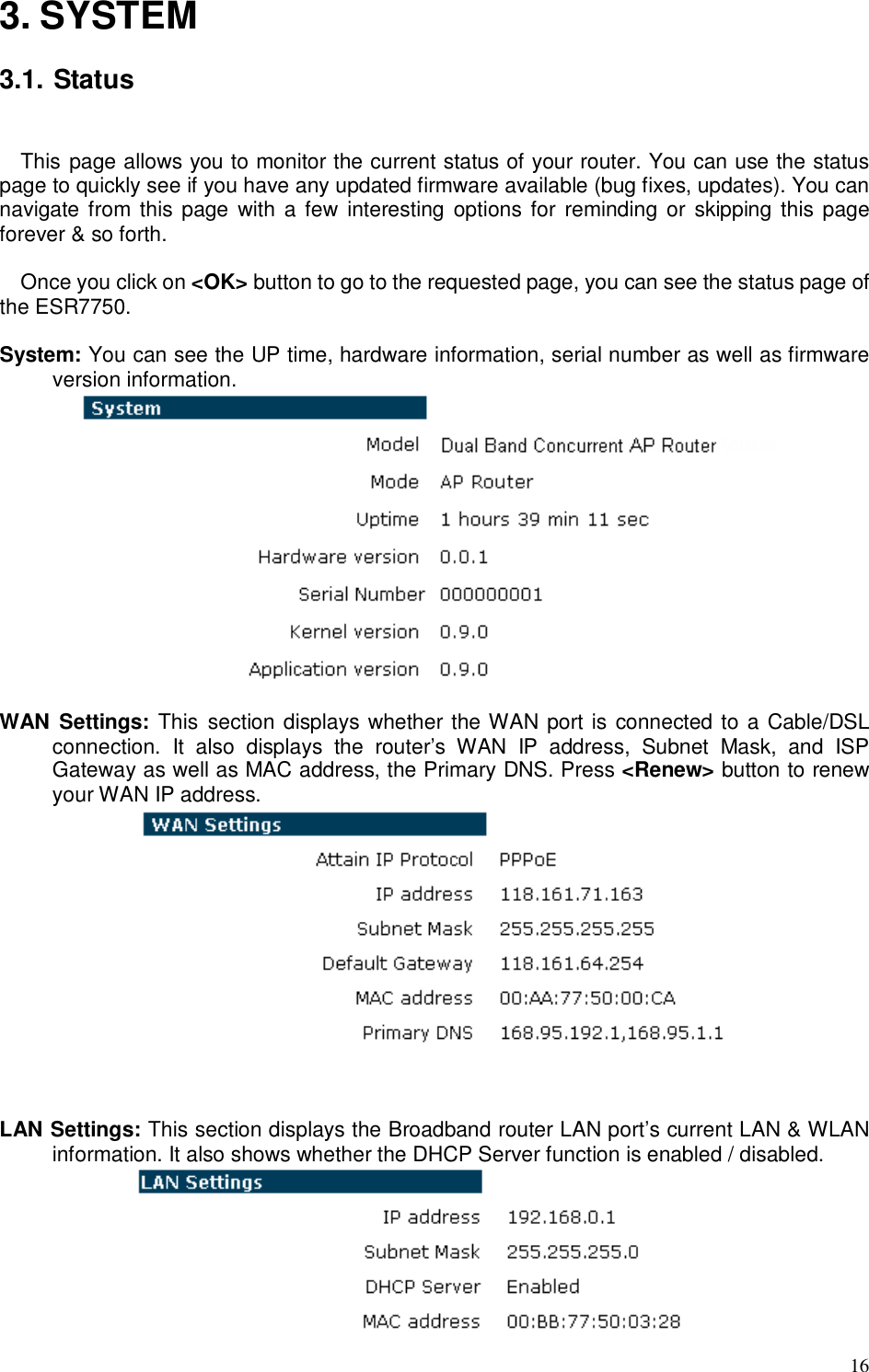
![14 2.7. Initial Setup ESR7750 ESR7750 provides web-interface for configuration through web browser, such as Internet Explorer, Firefox or Safari. 1. Open your browser (e.g. Internet Explorer). 2. Type in http://192.168.0.1 in the address bar and press [Enter]. 3. Click <OK> to navigate into ESR7750 configuration home page. 4. You will see the home page of ESR7750 as follows.](https://usermanual.wiki/Senao-Networks/SR7750/User-Guide-1127523-Page-18.png)