Senao Networks SR97107001 WLAN Gigabit 802.11n/b/g Router User Manual ESR 9701 UsersManual V1 0
Senao Networks, Inc. WLAN Gigabit 802.11n/b/g Router ESR 9701 UsersManual V1 0
Contents
- 1. Manual Part 1
- 2. Manual Part 2
Manual Part 1
Wireless N Gigabit Router
User’s Manual
Version: 1.0

ESR-9710 Wireless N Gigabit Router Version 1.0
2
Table of Contents
1 INTRODUCTION ................................................................................................................5
1.1 F
EATURES
&
B
ENEFITS
............................................................................................5
1.2 P
ACKAGE
C
ONTENTS
...............................................................................................6
1.3 S
AFETY
G
UIDELINES
................................................................................................6
1.4 W
IRELESS
SOHO
R
OUTER
D
ESCRIPTION
..................................................................7
1.5 S
YSTEM
R
EQUIREMENTS
..........................................................................................8
1.6 A
PPLICATIONS
.........................................................................................................8
1.7 N
ETWORK
C
ONFIGURATION
......................................................................................9
2 UNDERSTANDING THE HARDWARE .............................................................................10
2.1 H
ARDWARE
I
NSTALLATION
......................................................................................10
2.2 IP
A
DDRESS
C
ONFIGURATION
.................................................................................10
3 INTERNET CONNECTION WIZARD ................................................................................12
3.1 L
OGGING
I
N
..........................................................................................................12
3.1.1 DHCP
C
ONNECTION
(D
YNAMIC
IP
A
DDRESS
)...........................................................15
3.1.2 PPP
O
E
(P
OINT
-
TO
-P
OINT
P
ROTOCOL OVER
E
THERNET
)............................................16
3.1.3 PPTP
(P
OINT
-
TO
-P
OINT
T
UNNELING
P
ROTOCOL
) .....................................................17
3.1.4 L2TP
(L
AYER
2
T
UNNELING
P
ROTOCOL
) ..................................................................18
3.1.5 S
TATIC
IP
A
DDRESS
C
ONFIGURATION
.......................................................................19
3.1.6 B
IG
P
OND
..............................................................................................................21
4 WI-FI PROTECTED SETUP WIZARD...............................................................................22
4.1 L
OGGING
I
N
..........................................................................................................22
4.2 A
DD A
W
IRELESS
D
EVICE
.......................................................................................22
4.2.1 U
SING THE
PIN .....................................................................................................23
4.2.2 U
SING THE
P
USH
B
UTTON
......................................................................................24
5 WIRELESS NETWORK SETUP WIZARD.........................................................................25
5.1 L
OGGING
I
N
..........................................................................................................25
5.2 W
IRELESS
N
ETWORK
S
ETUP
..................................................................................25
5.2.1 A
UTOMATIC
N
ETWORK
S
ETUP
.................................................................................26
5.2.2 M
ANUAL
N
ETWORK
S
ETUP
.....................................................................................26
5.2.2.1 W
IRELESS
S
ECURITY
L
EVEL
:
BEST
(WPA2)............................................................28
5.2.2.2 W
IRELESS
S
ECURITY
L
EVEL
:
BETTER
(WPA) .........................................................29
5.2.2.3 W
IRELESS
S
ECURITY
L
EVEL
:
GOOD
(WEP
64/128-
BIT
) ...........................................30
5.2.2.4 W
IRELESS
S
ECURITY
L
EVEL
:
N
ONE
(S
ECURITY
D
ISABLED
).........................................31
6 ADVANCED WEB CONFIGURATION ..............................................................................32
6.1 L
OGGING
I
N
..........................................................................................................32
6.2 B
ASIC
...................................................................................................................33
6.2.1 W
IZARD
_W
IRELESS
...............................................................................................33
6.2.2 N
ETWORK
S
ETTINGS
..............................................................................................33
6.2.2.1 B
RIDGE
M
ODE
.......................................................................................................33
6.2.2.2 R
OUTER
M
ODE
.....................................................................................................34
6.2.3 W
IRELESS
S
ETTINGS
.............................................................................................35
6.2.3.1 W
IRELESS
S
ECURITY
M
ODE
...................................................................................36
6.2.3.1.1 WEP
(W
IRED
E
QUIVALENT
P
RIVACY
).......................................................................36
6.2.3.1.2 WPA
P
ERSONAL
(W
I
-F
I
P
ROTECTED
A
CCESS
)..........................................................37
6.2.3.1.3 WPA
E
NTERPRISE
(W
I
-F
I
P
ROTECTED
A
CCESS
&
802.1
X
) ........................................38
6.2.4 WAN
S
ETTINGS
....................................................................................................40
6.2.4.1 S
TATIC
IP
A
DDRESS
C
ONFIGURATION
.......................................................................40

ESR-9710 Wireless N Gigabit Router Version 1.0
3
Table of Contents
6.2.4.2 DHCP
C
ONNECTION
(D
YNAMIC
IP
A
DDRESS
)...........................................................41
6.2.4.3 PPP
O
E
(P
OINT
-
TO
-P
OINT
P
ROTOCOL OVER
E
THERNET
)............................................42
6.2.4.4 PPTP
(P
OINT
-
TO
-P
OINT
T
UNNELING
P
ROTOCOL
) .....................................................44
6.2.4.5 L2TP
(L
AYER
2
T
UNNELING
P
ROTOCOL
) ..................................................................45
6.2.5 B
IG
P
OND
..............................................................................................................46
6.3 A
DVANCED
............................................................................................................48
6.3.1 A
DVANCED
W
IRELESS
............................................................................................48
6.3.2 V
IRTUAL
S
ERVER
...................................................................................................49
6.3.3 S
PECIAL
A
PPLICATIONS
..........................................................................................50
6.3.4 P
ORT
F
ORWARDING
...............................................................................................51
6.3.5 S
TREAM
E
NGINE
....................................................................................................51
6.3.6 R
OUTING
..............................................................................................................54
6.3.7 A
CCESS
C
ONTROL
.................................................................................................54
6.3.8 W
EB
F
ILTER
..........................................................................................................57
6.3.9 MAC
A
DDRESS
F
ILTER
...........................................................................................57
6.3.10 F
IREWALL
.............................................................................................................58
6.3.11 I
NBOUND
F
ILTER
....................................................................................................61
6.3.12 WISH ..................................................................................................................62
6.3.13 W
I
-F
I
P
ROTECTED
S
ETUP
......................................................................................63
6.3.14 A
DVANCED
N
ETWORK
(UPNP,
WAN
P
ING
…)...........................................................64
6.4 T
OOLS
..................................................................................................................66
6.4.1 T
IME
Z
ONE
S
ETTING
..............................................................................................66
6.4.2 S
YSTEM
................................................................................................................67
6.4.2.1 S
AVE
C
ONFIGURATION TO A
F
ILE
.............................................................................67
6.4.2.2 R
ESTORE THE
C
ONFIGURATION FROM A
F
ILE
.............................................................68
6.4.2.3 R
ESTORE
S
ETTINGS TO
D
EFAULT
............................................................................69
6.4.2.4 S
YSTEM
R
EBOOT
...................................................................................................69
6.4.3 F
IRMWARE
U
PGRADE
.............................................................................................70
6.4.4 S
YSTEM
L
OGS
.......................................................................................................70
6.4.5 D
YNAMIC
DNS......................................................................................................71
6.4.6 S
YSTEM
C
HECK
.....................................................................................................71
6.4.7 S
CHEDULES
..........................................................................................................72
6.5 S
TATUS
................................................................................................................73
6.5.1 W
IRELESS
S
TATUS
.................................................................................................73
6.5.2 L
OGS
S
TATUS
........................................................................................................73
6.5.3 S
TATISTICS
...........................................................................................................74
6.5.4 WISH
S
ESSION
S
TATUS
.........................................................................................75
6.5.5 I
NTERNET
S
ESSION
S
TATUS
....................................................................................76
APPENDIX A – GLOSSARY.....................................................................................................77
APPENDIX B – SPECIFICATIONS ...........................................................................................89
H
ARDWARE
S
UMMARY
.............................................................................................................89
R
ADIO
S
PECIFICATIONS
............................................................................................................89
R
OUTER AND
G
ATEWAY
............................................................................................................90
M
ANAGEMENT
.........................................................................................................................91
E
NVIRONMENT
&
P
HYSICAL
......................................................................................................92
APPENDIX C – FCC INTERFERENCE STATEMENT ...............................................................93
APPENDIX D – INDEX..............................................................................................................94

ESR-9710 Wireless N Gigabit Router Version 1.0
4
Revision History
Version Date Notes
1.0 September 12, 2007 Initial Version

ESR-9710 Wireless N Gigabit Router Version 1.0
5
1 Introduction
The Wireless-N Gigabit Router is a draft 802.11n compliant device that delivers up to 6x
faster speeds than 802.11g while staying backward compatible with 802.11g and 802.11b
devices.
It is not only a Wireless Access Point, which lets you connect to the network without
wires. There's also a built-in 4-port full-duplex 10/100/1000 Gigabit Switch to connect
your wired-Ethernet devices together. The Router function ties it all together and lets
your whole network share a high-speed cable or DSL Internet connection.
The Access Point built into the Router uses advanced MIMO (Multi-Input, Multi-Output)
technology to transmit multiple steams of data in a single wireless channel. The robust
signal travels farther, maintaining wireless connections up to 3 times farther than
standard 802.11g, eliminates dead spots and extends network range.
To protect the data and privacy, the Router can encode all wireless transmissions with
64/128-bit encryption. It can serve as your network's DHCP Server, has a powerful SPI
firewall to protect your PCs against intruders and most known Internet attacks, and
supports VPN pass-through. The router also provide easy configuration with the web
browser-based configuration utility.
The incredible speed and QoS function of 802.11n (draft2.0) Gigabit Router is ideal for
media-centric applications like streaming video, gaming, and VoIP telephony. It is
designed to run multiple media-intense data streams through the network at the same
time, with no degradation in performance.
This chapter describes the features & benefits, package contents, applications, and
network configuration.
1.1 Features & Benefits
Features Benefits
High Speed Data Rate Up to 300Mbps Capable of handling heavy data payloads
such as MPEG video streaming
IEEE 802.11n draft Compliant and
backward compatible with 802.11b/g Fully interoperable with IEEE 802.11b/g/n
devices
Four built-in 10/100/1000Mbps Gigabit
Switch Ports (Auto-Crossover) Scalability, able to extend your network
Supports DNS/ DDNS Lets users assign a fixed host and domain
name to a dynamic Internet IP address.
Supports NAT (Network Address
Translation)/NAPT
Shares single Internet account and provides a
type of firewall by hiding internal IP addresses
for keeping hacker out
Hide SSID Avoids unallowable users sharing bandwidth,
increases efficiency of the network
Firewall supports Virtual Server
Mapping, DMZ, IP Filter, ICMP Blocking,
Avoids the attacks of Hackers or Viruses from
Internet

ESR-9710 Wireless N Gigabit Router Version 1.0
6
SPI
Support 802.1x authenticator, 802.11i
(WPA/WPA2, AES), VPN pass-thru
mechanisms
Provide mutual authentication (Client and
dynamic encryption keys to enhance security
WDS (Wireless Distribution System) Make wireless AP and Bridge mode
simultaneously as a wireless repeater
Universal Plug and Play (UPnP™) Works with most Internet gaming and instant
messaging applications for automatic Internet
access
Filter Scheduling The filter can be scheduled by days, hours or
minutes for easy management
Real time alert The detection of a list for Hacker log-in
information
Web configuration Helps administrators to remotely configure or
manage the Router via Telnet/Web-browser
1.2 Package Contents
Open the package carefully, and make sure that none of the items listed below are
missing. Do not discard the packing materials, in case of return; the unit must be shipped
in its original package.
One Wireless N Gigabit Router
One
12V/1.25A 90V~240V
Power Adapter
Three 2dBi 2.4GHz Dipole Antennas
One CD-ROM with User’s Manual
Once Quick Guide
1.3 Safety Guidelines
In order to reduce the risk of fire, electric shock and injury, please adhere to the following
safety guidelines.
Carefully follow the instructions in this manual; also follow all instruction labels
on this device.
Except for the power adapter supplied, this device should not be connected to
any other adapters.
Do not spill liquid of any kind on this device.
Do not place the unit on an unstable stand or table. This unit may drop and
become damaged.
Do not expose this unit to direct sunlight.
Do not place any hot devices close to this unit, as they may degrade or cause
damage to the unit.
Do not place any heavy objects on top of this unit.
Do not use liquid cleaners or aerosol cleaners. Use a soft dry cloth for cleaning.
ESR-9710 Wireless N Gigabit Router Version 1.0
7
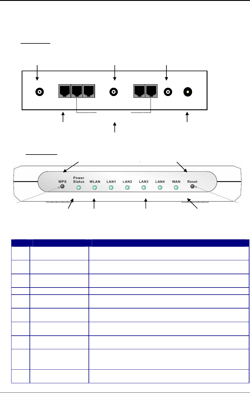
1.4 Wireless SOHO Router Description
WAN
WAN LAN: 4*RJ45
LAN: 4*RJ45
10/100/1000M
10/100/1000M
DC JACK
DC JACK
SMA
SMA SMA
SMA SMA
SMA
WAN
WAN LAN: 4*RJ45
LAN: 4*RJ45
10/100/1000M
10/100/1000M
DC JACK
DC JACK
SMA
SMA SMA
SMA SMA
SMA
Step
Label Description
1 LAN Ports (1 – 4) Use an Ethernet cable to connect each port to a computer
on your Local Area Network (LAN).
2 WAN Port Use an Ethernet cable to connect this port to your WAN
router.
3 DC Connector Use the power cable and connect the adapter to the power
socket on the wall, and the DC inlet into the DC connector.
4 Antenna Connector Connect the three antennas to the SMA connectors.
Connection / Activity
LED This LED will light up once an Ethernet cable is connected
to one of the LAN ports.
WAN LED This LED will light up once an Ethernet cable is connected
to WAN (Internet) port.
WLAN LED This LED will light up once the RF (wireless LAN) feature is
enabled
Power LED This LED will light up once the power cable is connected to
the DC connector.
Reset Button Use this button to reset the device. You can restore the
device back to its factory default settings by holding down
on this button for 5 seconds.
WPS WPS (Wireless Push Button) is used for WiFi Protected
Setup. By pressing this button, the security settings of the
LAN Ports (1
-
4)
WAN Port DC Connector
LAN 1- 4 LED
Power LED
Rear
Panel
Front
Panel
WLAN LED
WAN LED
Antenna
Connector
Antenna
Connector
Antenna
Connector
Reset Button WPS Button

ESR-9710 Wireless N Gigabit Router Version 1.0
8
device will automatically synchronize with other wireless
devices on your network that support Wi-Fi Protected Setup.
1.5 System Requirements
The following are the minimum system requirements in order configure the device.
PC/AT compatible computer with a Ethernet interface.
Operating system that supports HTTP web-browser
1.6 Applications
The wireless LAN products are easy to install and highly efficient. The following list
describes some of the many applications made possible through the power and flexibility
of wireless LANs:
a) Difficult-to-wire environments
There are many situations where wires cannot be laid easily. Historic
buildings, older buildings, open areas and across busy streets make the
installation of LANs either impossible or very expensive.
b) Temporary workgroups
Consider situations in parks, athletic arenas, exhibition centers, disaster-
recovery, temporary offices and construction sites where one wants a
temporary WLAN established and removed.
c) The ability to access real-time information
Doctors/nurses, point-of-sale employees, and warehouse workers can
access real-time information while dealing with patients, serving customers
and processing information.
d) Frequently changed environments
Show rooms, meeting rooms, retail stores, and manufacturing sites where
frequently rearrange the workplace.
e) Small Office and Home Office (SOHO) networks
SOHO users need a cost-effective, easy and quick installation of a small
network.
f) Wireless extensions to Ethernet networks
Network managers in dynamic environments can minimize the overhead
caused by moves, extensions to networks, and other changes with wireless
LANs.
g) Wired LAN backup
Network managers implement wireless LANs to provide backup for mission-
critical applications running on wired networks.
h) Training/Educational facilities
Training sites at corporations and students at universities use wireless
connectivity to ease access to information, information exchanges, and
learning.
ESR-9710 Wireless N Gigabit Router Version 1.0
9
1.7 Network Configuration
To better understand how the wireless LAN products work together to create a
wireless network, it might be helpful to depict a few of the possible wireless LAN PC
card network configurations. The wireless LAN products can be configured as:
a) Ad-hoc (or peer-to-peer) for departmental or SOHO LANs.
b) Infrastructure for enterprise LANs.
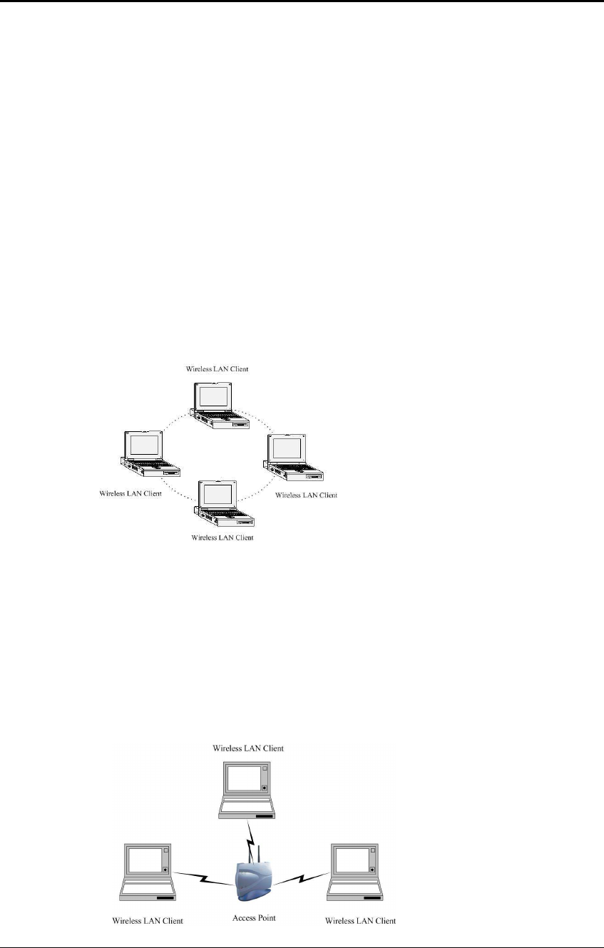
a) Ad-hoc (peer-to-peer) Mode
This is the simplest network configuration with several computers
equipped with the PC Cards that form a wireless network whenever they
are within range of one another. In ad-hoc mode, each client is peer-to-
peer, would only have access to the resources of the other client and
does not require an access point. This is the easiest and least expensive
way for the SOHO to set up a wireless network. The image below depicts
a network in ad-hoc mode.
b) Infrastructure Mode
The infrastructure mode requires the use of an access point (AP). In this
mode, all wireless communication between two computers has to be via
the AP. It doesn’t matter if the AP is stand-alone or wired to an Ethernet
network. If used in stand-alone, the AP can extend the range of
independent wireless LANs by acting as a repeater, which effectively
doubles the distance between wireless stations. The image below
depicts a network in infrastructure mode.
ESR-9710 Wireless N Gigabit Router Version 1.0
10
2 Understanding the Hardware
2.1 Hardware Installation
1. Place the unit in an appropriate location after conducting a site survey.
2. Plug one end of the Ethernet cable into the LAN port of the device and another end
into your PC/Notebook.
3. Plug one end of another Ethernet cable to WAN port of the device and the other end
into you cable/DSL modem (Internet)
4. Insert the DC-inlet of the power adapter into the port labeled “DC-IN” and the other
end into the power socket on the wall.
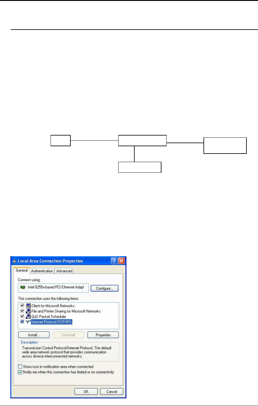
This diagram depicts the hardware configuration
2.2 IP Address Configuration
This device can be configured as a Bridge/Router or Access Point. The default IP
address of the device is 192.168.1.2 In order to log into this device, you must first
configure the TCP/IP settings of your PC/Notebook.
1. In the control panel, double click Network Connections and then double click on the
connection of your Network Interface Card (NIC). You will then see the following
screen.
WLAN Router
PC
Power Outlet
Ethernet
AC/DC cable
Ethernet
Cable / DSL
Modem
ESR-9710 Wireless N Gigabit Router Version 1.0
11
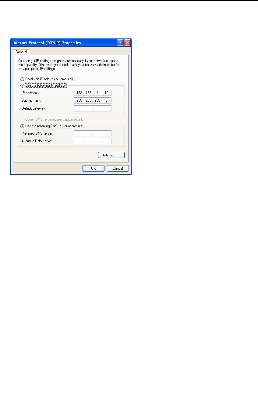
2. Select Internet Protocol (TCP/IP) and then click on the Properties button. This will
allow you to configure the TCP/IP settings of your PC/Notebook.
3. Select Use the following IP Address radio button and then enter the IP address
and subnet mask. Ensure that the IP address and subnet mask are on the same
subnet as the device.
For Example: Device IP address: 192.168.1.2
PC IP address: 192.168.1.10
PC subnet mask: 255.255.255.0
4. Click on the OK button to close this window, and once again to close LAN properties
window.
ESR-9710 Wireless N Gigabit Router Version 1.0
12
3 Internet Connection Wizard
This device offers a quick and simple configuration through the use of wizards. This
chapter describes how to use the wizard to configure the WAN, LAN, and wireless
settings. Please refer to Chapter 6 in order to configure the more advanced features of
the device.
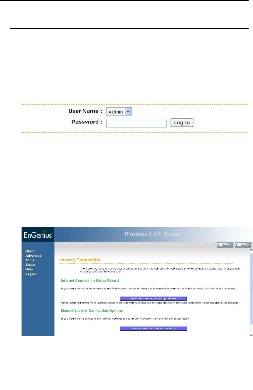
3.1 Logging In
To configure the device through the web-browser, enter the IP address of the device
(default: 192.168.1.2) into the address bar of the web-browser and press Enter.
Make sure that the device and your computers are configured on the same subnet.
Refer to Chapter 2 in order to configure the IP address of your computer.
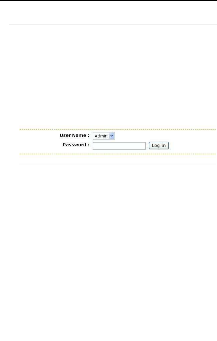
After connecting to the IP address, the web-browser will display the login page.
Select Admin from the drop-down list and then leave the password field blank. Click
on the Log In button to continue.
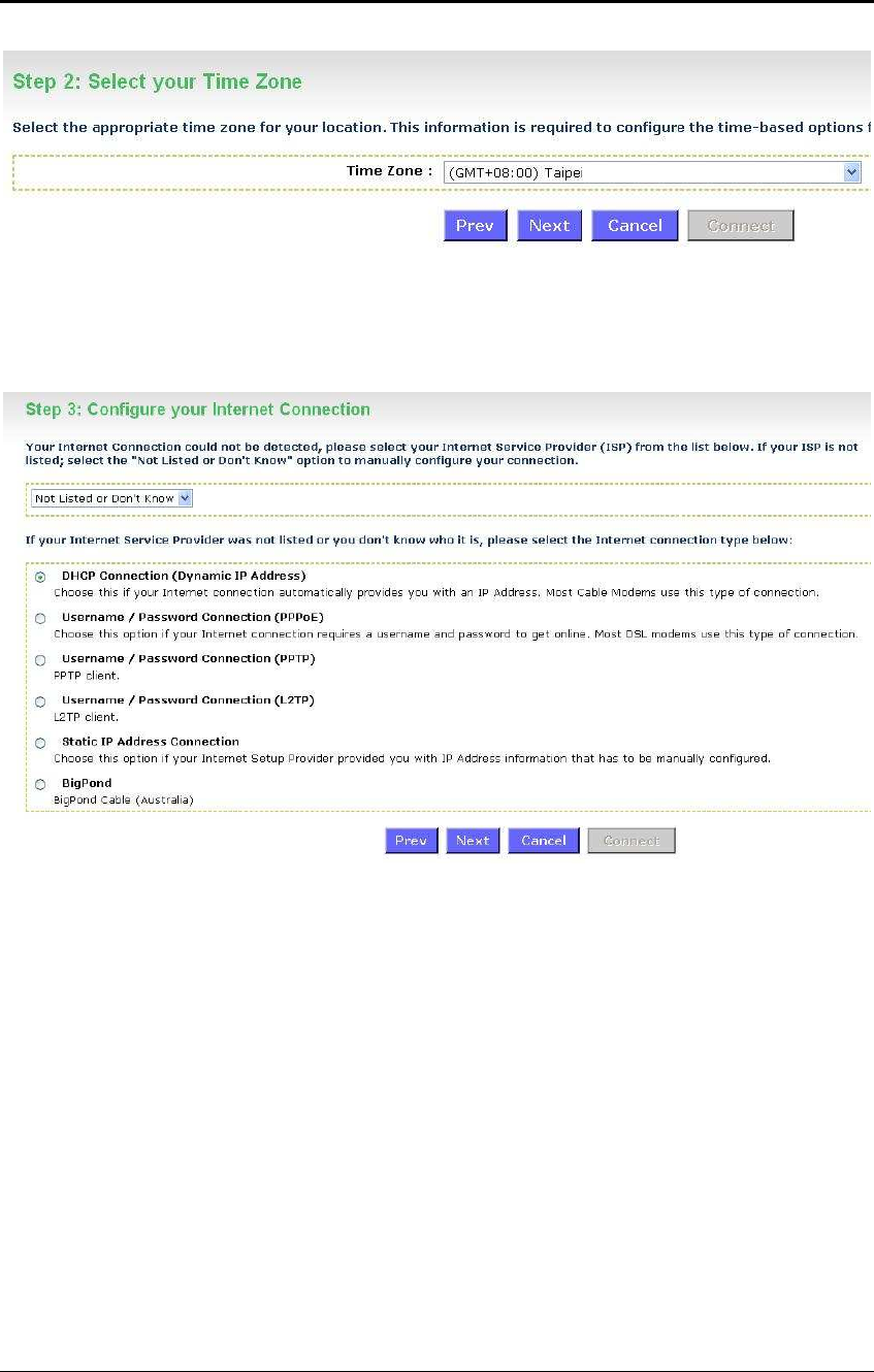
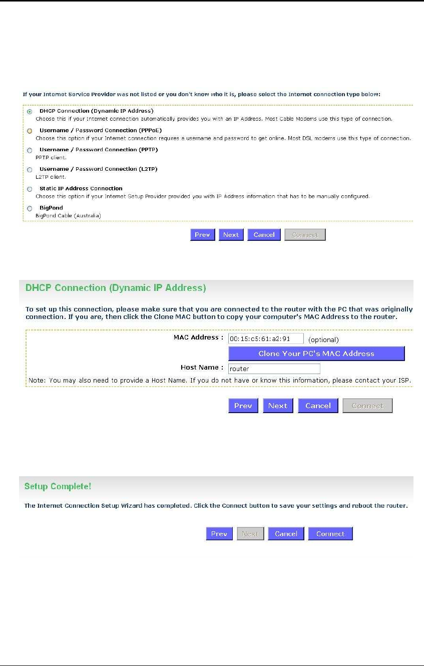
This device supports several types of WAN connections:
o DHCP Connection (Dynamic IP address) – Choose this connection type if
your ISP provides you the IP address. Most cable modems use this type of
connection.
o PPPoE (Poinit-to-Point Protocol over Ethernet) – Choose this option if
your internet connection requires a user name and password. Most DSL
modems use this type of connection.
o PPTP (Point-to-Point Tunneling Protocol) – Choose this type of
connection if your ISP requires you to use PPTP. Your ISP should provide
you with a user name and password.
o Static IP address – Choose this option if you have a dedicated IP address.
o BigPond – Choose this option if you use the BigPond service in Australia.
The configuration wizard for each connection type is described below.
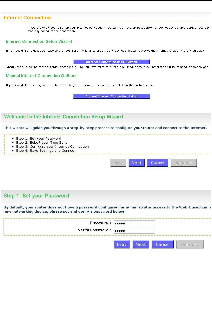
Click on the Internet Connection Setup Wizard button to begin the process.
ESR-9710 Wireless N Gigabit Router Version 1.0
13
Click on the Internet Connection Setup Wizard Setup button to begin the process.
The Wizard requires that you configure the password, time zone, and Internet (WAN)
connection. Click on the Next button to continue.
By default, the device does not use a password. Specify a password for administrator
access to the device, then type the password once more in the Verify Password
field. Click on the Next button to continue.
ESR-9710 Wireless N Gigabit Router Version 1.0
14
Select your time zone from the drop-down list Click on the Next button to continue.
The next step in the wizard is the Internet Connection, select the WAN connection
type from the list, and then click on the Next button to continue with the wizard.
ESR-9710 Wireless N Gigabit Router Version 1.0
15
3.1.1 DHCP Connection (Dynamic IP Address)
The WAN interface can be configured as a DHCP Client in which the ISP provides
the IP address to the device. This is also known as Dynamic IP.
Select the DHCP Connection (Dynamic IP Address) radio button and then click on
the Next button.
You have the option of cloning your PCs MAC address onto the device. Click on the
Clone Your PCs MAC Address to automatically copy the MAC address. You may
also specify a host name. Click on the Next button to continue.
The WAN configuration is complete. Click on the Connect button to connect to the
Internet.
ESR-9710 Wireless N Gigabit Router Version 1.0
16
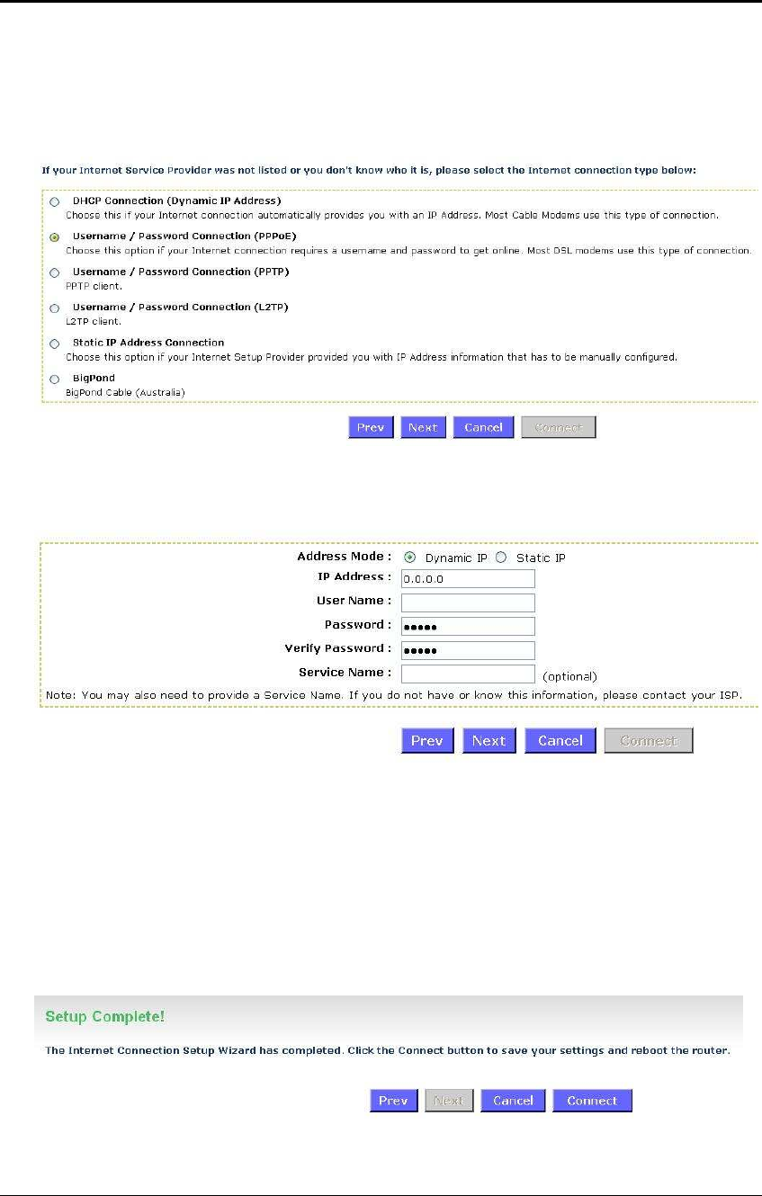
3.1.2 PPPoE (Point-to-Point Protocol over Ethernet)
The WAN interface can be configured as PPPoE. This type of connection is usually
used for a DSL service and requires a username and password to connect.
Select the Username / Password Connection (PPPoE) radio button and then click
on the Next button.
Address Mode: PPPoE can be used with a dynamic or static IP address. If you
select the Dynamic IP radio button, then the IIP address in the next field is not
required. However, if you select the Static IP radio button, then the IP address in the
next field is required.
User Name: Specify the user name which is provided by your ISP.
Password: Specify the password which is provided by your ISP, and then verify it
once again in the next field.
Service Name: Specify the name of the ISP.
Click on the Next button to continue.
ESR-9710 Wireless N Gigabit Router Version 1.0
17
The WAN configuration is complete. Click on the Connect button to connect to the
Internet.
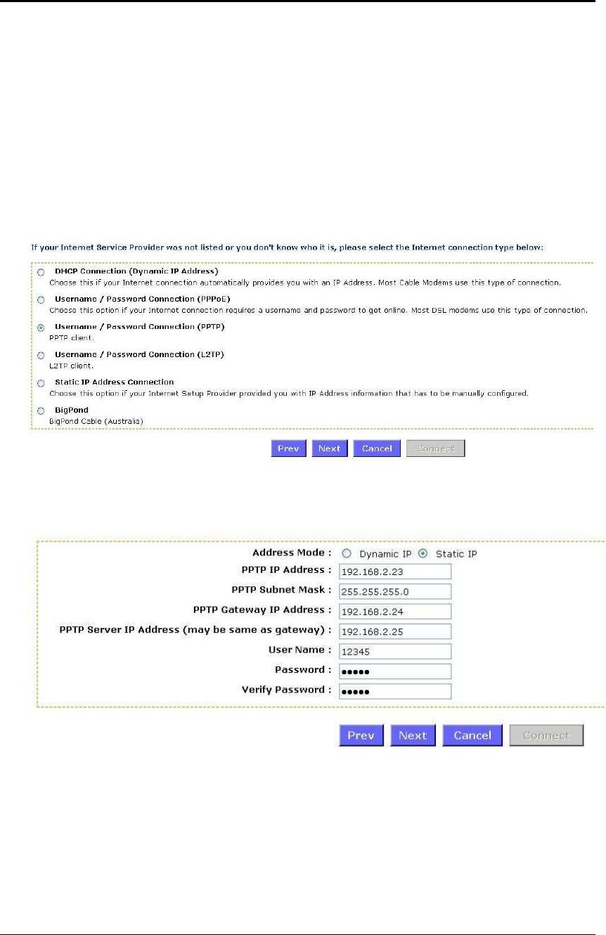
3.1.3 PPTP (Point-to-Point Tunneling Protocol)
The WAN interface can be configured as PPTP. PPTP (Point to Point Tunneling
Protocol) uses a virtual private network to connect to your ISP. This method of
connection is primarily used in Europe. This method of connection requires you to
enter a username and password (provided by your ISP) to gain access to the Internet.
The supported authentication protocols are PAP and CHAP.
Select the Username / Password Connection (PPTP) radio button and then click
on the Next button.
Address Mode: PPTP can be used with a dynamic or static IP address. If you select
the Dynamic IP radio button, then the IIP address in the next field is not required.
However, if you select the Static IP radio button, then the IP address in the next field
is required.
PPTP Address: Specify the IP address
PPTP Subnet Mask: Specify the subnet mask for the IP address.
PPTP Gateway IP Address: Specify the IP address of the PPTP gateway.
PPTP Server IP Address: If the PPTP Server’s IP address is different from the
default gateway, then you may specify it here.
ESR-9710 Wireless N Gigabit Router Version 1.0
18
User Name: Specify the user name which is provided by your ISP.
Password: Specify the password which is provided by your ISP, and then verify it
once again in the next field.
Click on the Next button to continue.
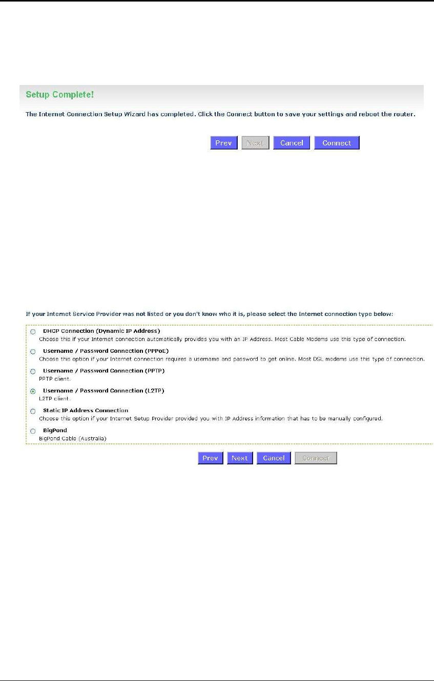
The WAN configuration is complete. Click on the Connect button to connect to the
Internet.
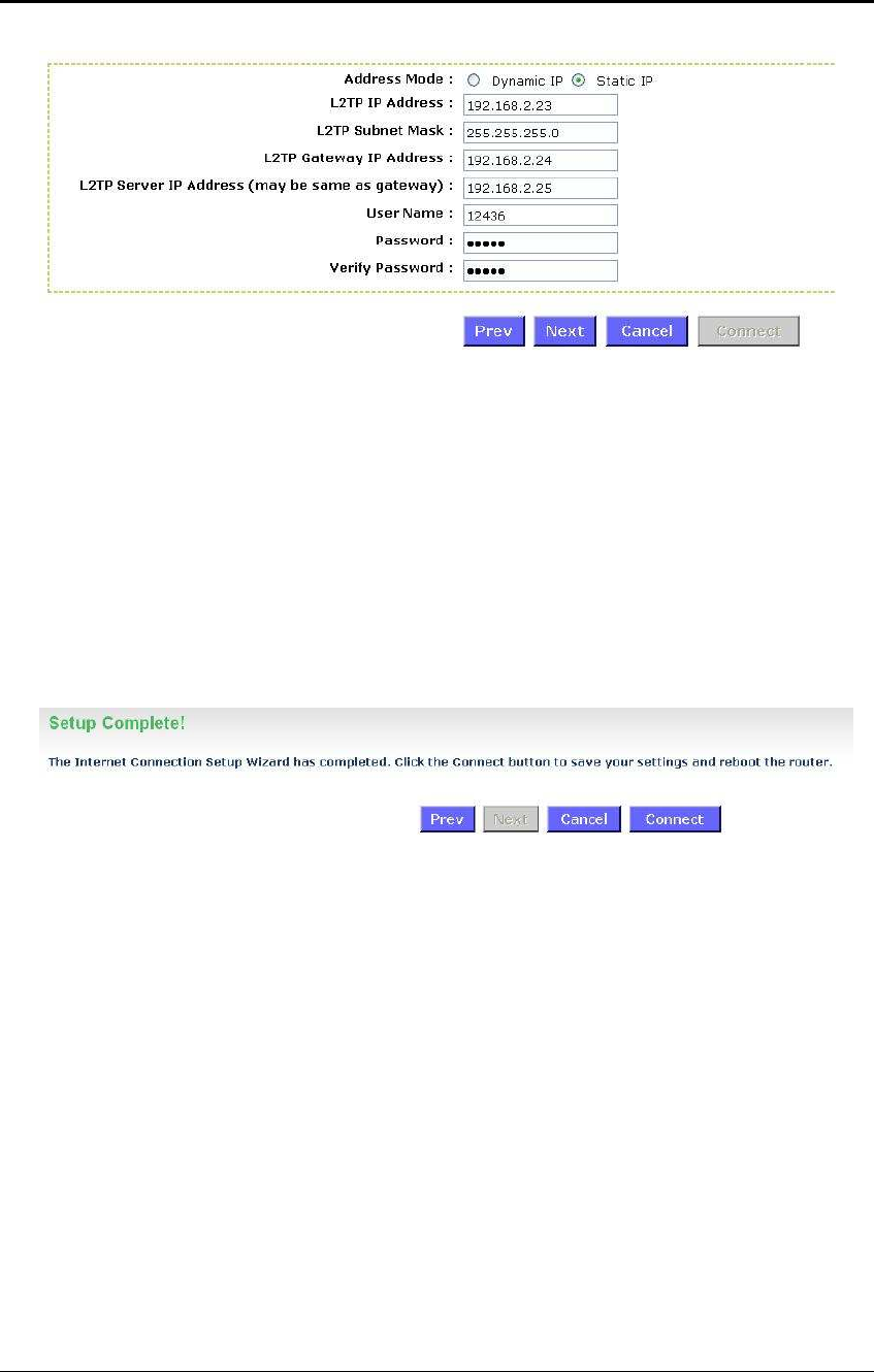
3.1.4 L2TP (Layer 2 Tunneling Protocol)
The WAN interface can be configured as L2TP. L2TP (Layer Two Tunneling Protocol)
uses a virtual private network to connect to your ISP. This method of connection
requires you to enter a user name and password (provided by your Internet Service
Provider) to gain access to the Internet. The supported authentication protocols are
PAP and CHAP.
Select the Username / Password Connection (L2TP) radio button and then click on
the Next button.
ESR-9710 Wireless N Gigabit Router Version 1.0
19
Address Mode: L2TP can be used with a dynamic or static IP address. If you select
the Dynamic IP radio button, then the IIP address in the next field is not required.
However, if you select the Static IP radio button, then the IP address in the next field
is required.
L2TP Address: Specify the IP address
L2TP Subnet Mask: Specify the subnet mask for the IP address.
L2TP Gateway IP Address: Specify the IP address of the L2TP gateway.
L2TP Server IP Address: If the L2TP Server’s IP address is different from the
default gateway, then you may specify it here.
User Name: Specify the user name which is provided by your ISP.
Password: Specify the password which is provided by your ISP, and then verify it
once again in the next field.
Click on the Next button to continue.
The WAN configuration is complete. Click on the Connect button to connect to the
Internet.
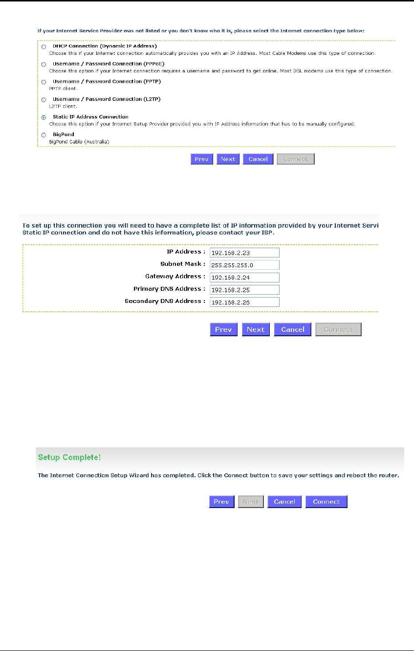
3.1.5 Static IP Address Configuration
The WAN interface can be configured as Static IP address. In this type of connection,
your ISP provides you with a dedicated IP address (which does not change as
DHCP).
ESR-9710 Wireless N Gigabit Router Version 1.0
20
Select the Static IP Address Connection radio button and then click on the Next
button.
IP Address: Specify the IP address for this device, which is assigned by your ISP.
Subnet Mask: Specify the subnet mask for this IP address, which is assigned by
your ISP.
Gateway Address: Specify the IP address of the default gateway, which is assigned
by your ISP.
Primary / Secondary DNS Address: Specify the primary and secondary IP address,
which is assigned by your ISP.
The WAN configuration is complete. Click on the Connect button to connect to the
Internet.
ESR-9710 Wireless N Gigabit Router Version 1.0
21
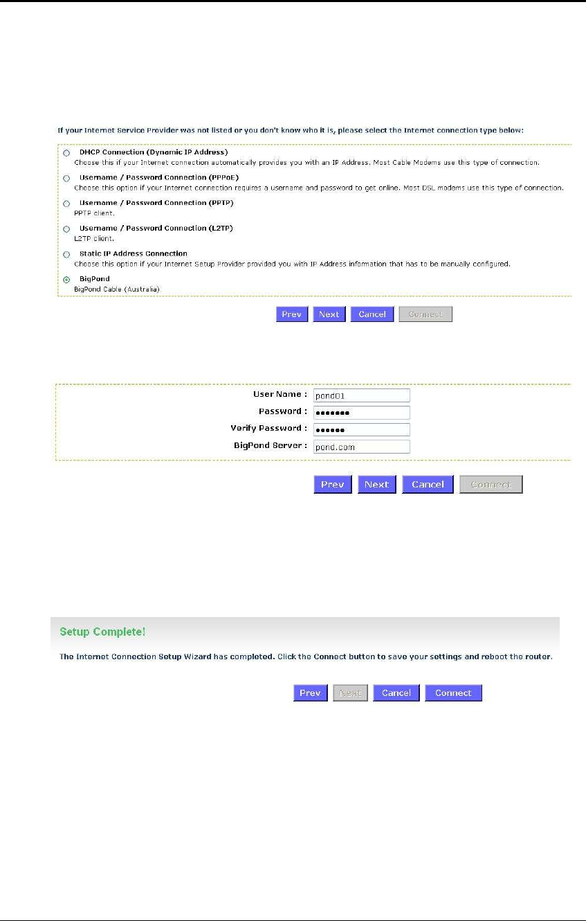
3.1.6 BigPond
The WAN interface can be configured as BigPong. This type of service is used
through Telstra BigPond Cable Broadband in Australia
Select the BigPond radio button and then click on the Next button.
User Name: Specify the user name which is provided by your ISP.
Password: Specify the password which is provided by your ISP, and then verify it
once again in the next field.
BingPond Server: Specify the server name or IP address as specified by your ISP.
Click on the Next button to continue.
The WAN configuration is complete. Click on the Connect button to connect to the
Internet.
ESR-9710 Wireless N Gigabit Router Version 1.0
22
4 Wi-Fi Protected Setup Wizard
Wi-Fi Protected Setup is a feature that locks the wireless security settings and prevents
the settings from being changed by any new external registrar using its PIN. Devices can
still be added to the wireless network using Wi-Fi Protected Setup.
.Please refer to Chapter 6 in order to configure the more advanced features of the device
4.1 Logging In
To configure the device through the web-browser, enter the IP address of the device
(default: 192.168.1.2) into the address bar of the web-browser and press Enter.
Make sure that the device and your computers are configured on the same subnet.
Refer to Chapter 2 in order to configure the IP address of your computer.
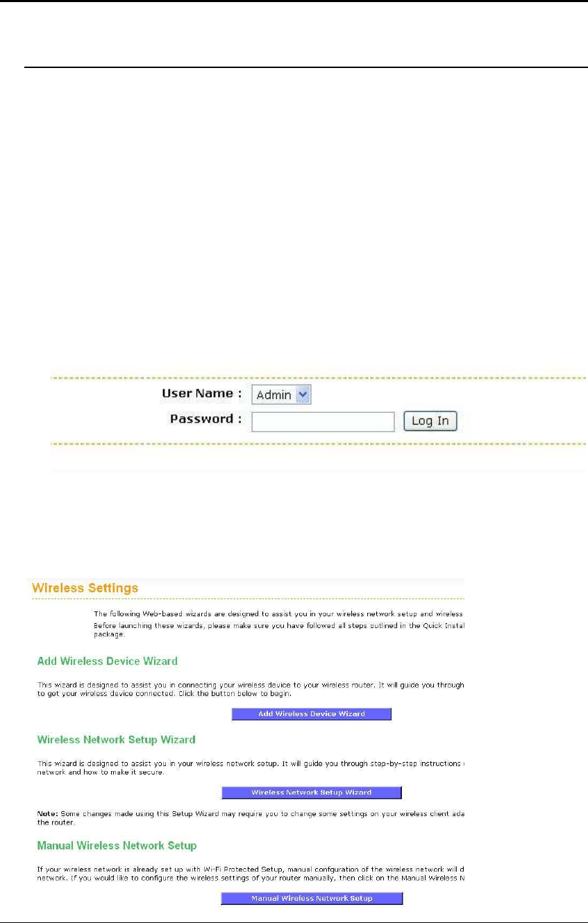
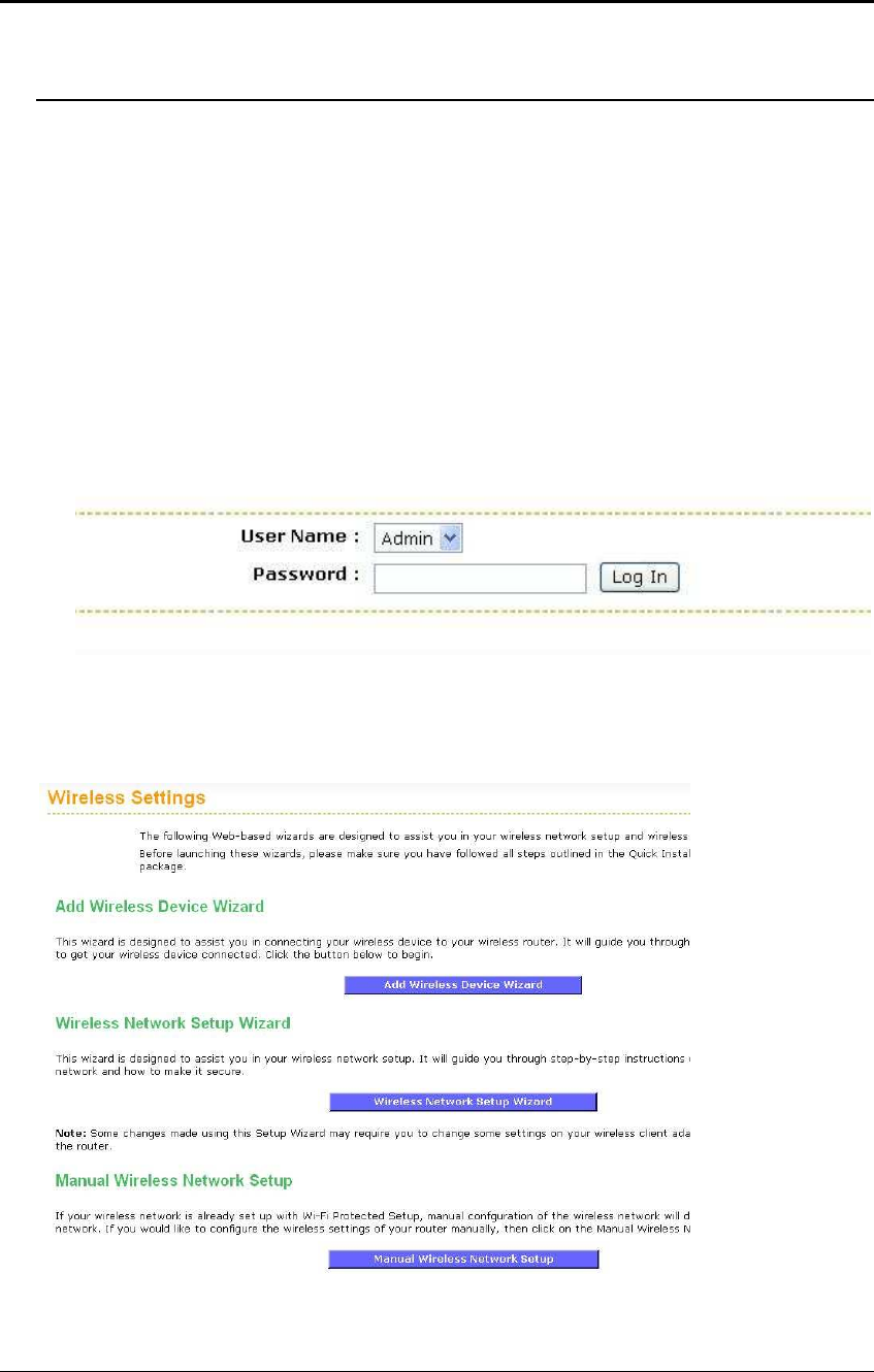
After connecting to the IP address, the web-browser will display the login page.
Select Admin from the drop-down list and then leave the password field blank. Click
on the Log In button to continue.
4.2 Add a Wireless Device
Click on the Wizard_Wireless link under the Basic menu, and then click on the Add
Wireless Device Wizard button.
ESR-9710 Wireless N Gigabit Router Version 1.0
23
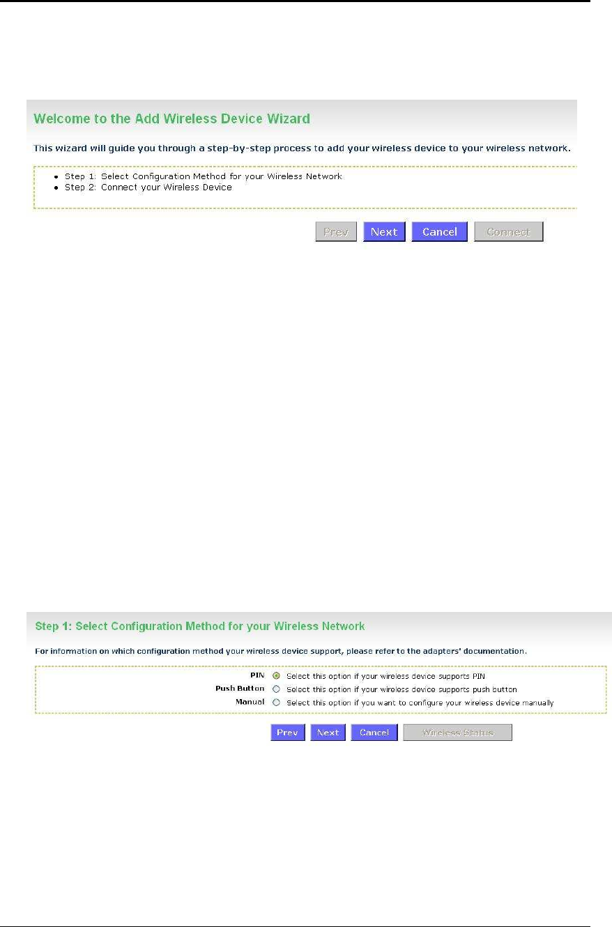
The wireless wizard will inform you that there are two major steps in the process.
o Select the configuration method for your wireless network
o Connect your wireless device
Click on the Next button to continue.
You may select from three available options:
o PIN: Select this radio button if your wireless device supports PIN
o Push Button: Select this radio button if your wireless device supports push
button.
o Manual: Select the radio button if you would like to setup your wireless
device manually. Refer to chapter 5 in order to manually configure the device.
The wizard will either display the wireless network settings to guide you through
manual configuration, prompt you to enter the PIN for the device, or ask you to press
the configuration button on the device. If the device supports Wi-Fi Protected Setup
and has a configuration button, you can add it to the network by pressing the
configuration button on the device and then the on the router within 60 seconds. The
status LED on the router will flash three times if the device has been successfully
added to the network.
There are several ways to add a wireless device to your network. Access to the
wireless network is controlled by a registrar. A registrar only allows devices onto the
wireless network if you have entered the PIN, or pressed a special Wi-Fi Protected
Setup button on the device. The router acts as a registrar for the network, although
other devices may act as a registrar as well.
4.2.1 Using the PIN
A PIN is a unique number that can be used to add the router to an existing network
or to create a new network. The default PIN may be printed on the bottom of the
router. For extra security, a new PIN can be generated. You can restore the default
PIN at any time. Only the Administrator ("admin" account) can change or reset the
PIN.
ESR-9710 Wireless N Gigabit Router Version 1.0
24
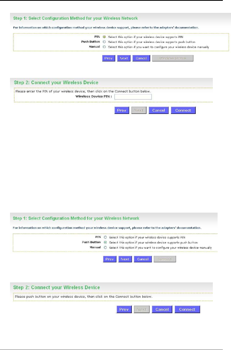
Select the PIN radio button and then click on the Next button.
Specify the PIN and then click on the Connect button.
The wireless device configuration is now complete.
4.2.2 Using the Push Button
WPS is used for WiFi Protected Setup. By pressing the WPS button on the front
panel of the device, the security settings of the device will automatically synchronize
with other wireless devices on your network that support Wi-Fi Protected Setup
If the device supports Wi-Fi Protected Setup and has a configuration button, you can
add it to the network by pressing the configuration button on the device and then the
on the router within 60 seconds. The status LED on the router will flash three times if
the device has been successfully added to the network.
Select the Push Button radio button and then click on the Next button.
Press the WPS button on the device (which is located on the left side of the front
panel) and then click on the Next button.
ESR-9710 Wireless N Gigabit Router Version 1.0
25
5 Wireless Network Setup Wizard
This wizard will guide you in the configuration of the wireless network settings such as
the SSID and security (WEP/WPA).
.Please refer to Chapter 6 in order to configure the more advanced features of the device
5.1 Logging In
To configure the device through the web-browser, enter the IP address of the device
(default: 192.168.1.2) into the address bar of the web-browser and press Enter.
Make sure that the device and your computers are configured on the same subnet.
Refer to Chapter 2 in order to configure the IP address of your computer.
After connecting to the IP address, the web-browser will display the login page.
Select Admin from the drop-down list and then leave the password field blank. Click
on the Log In button to continue.
5.2 Wireless Network Setup
Click on the Wizard_Wireless link under the Basic menu, and then click on the
Wireless Network Setup Wizard button.
The wizard will inform you that there are two options: auto and manual.
ESR-9710 Wireless N Gigabit Router Version 1.0
26
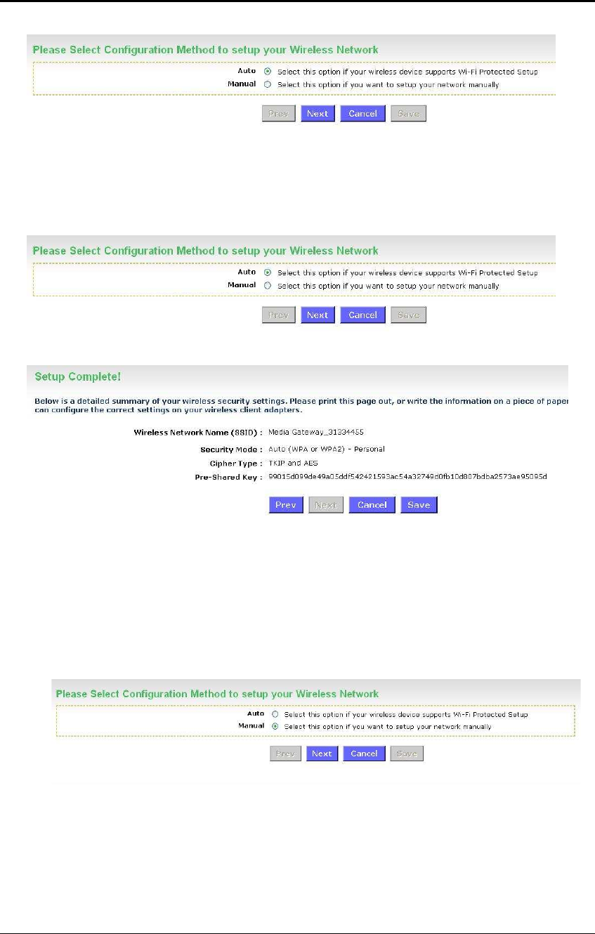
5.2.1 Automatic Network Setup
If you select the Auto option, then the device will automatically configure the SSID
and security mode.
Click on the Next button to continue.
The wizard has automatically configured the SSID and security mode for the device.
Click on the Save button to complete the setup.
5.2.2 Manual Network Setup
If you select the Manual option, then you will be required to specify the SSID and
select the appropriate network security.
Click on the Next button to continue.
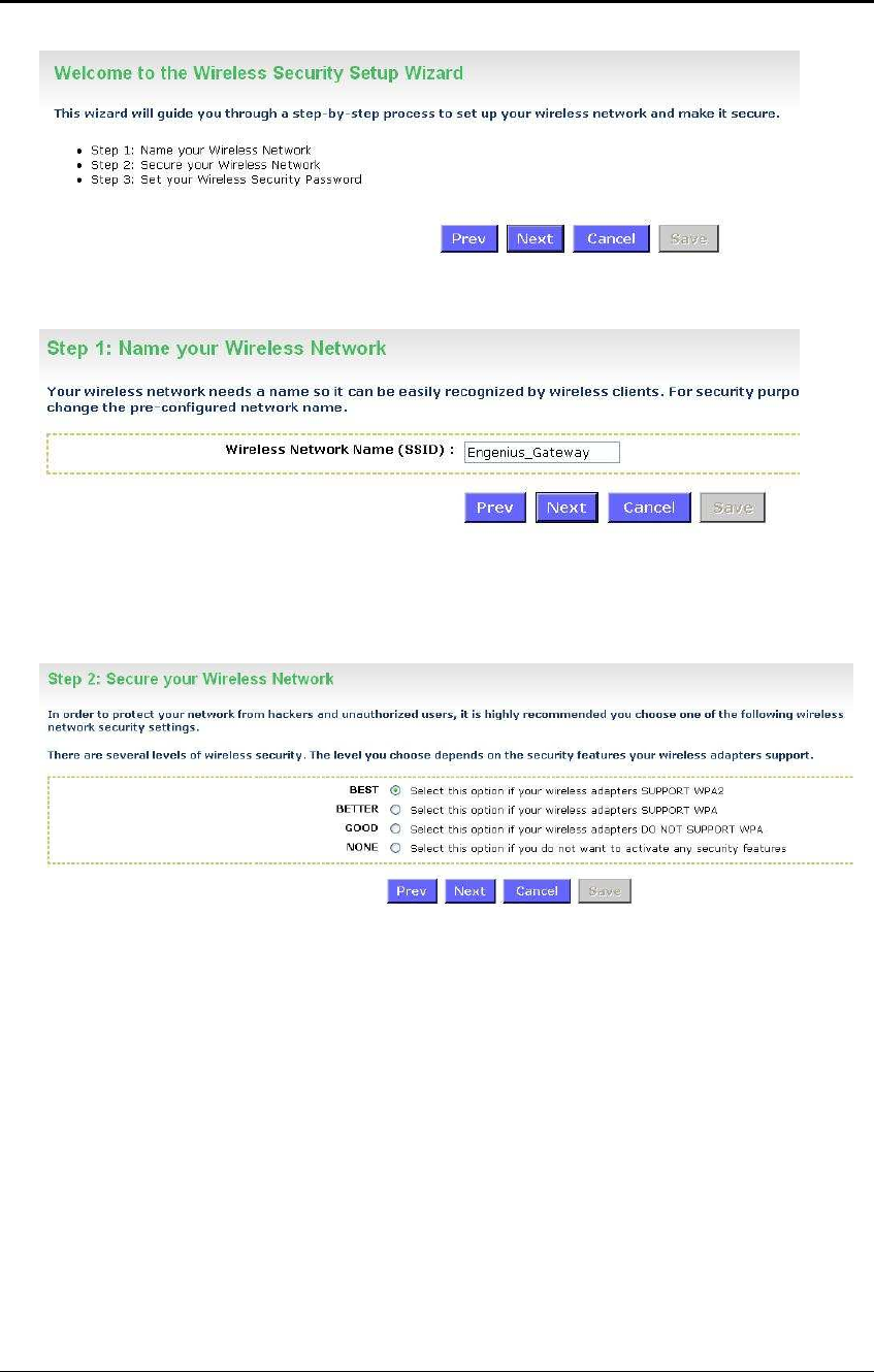
The wireless wizard will inform you that there are three major steps in the process.
o Name your wireless network
o Secure your wireless network
o Set your wireless security password
ESR-9710 Wireless N Gigabit Router Version 1.0
27
Click on the Next button to continue.
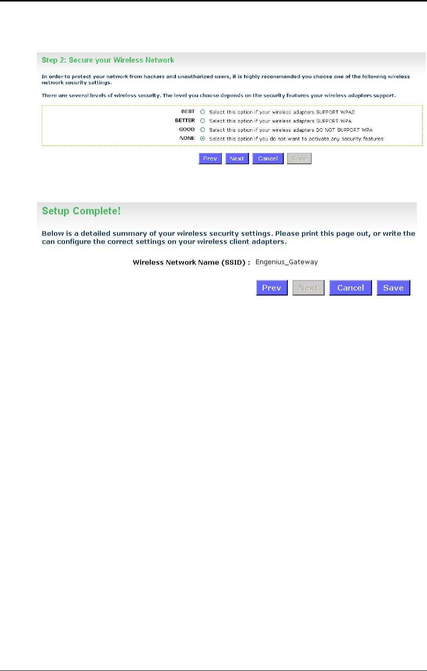
Specify the Wireless Network Name (SSID) for the device. The SSID is a unique
named shared amongst all the points of the wireless network. The SSID must be
identical on all points of the wireless network and cannot exceed 32 characters.
Click on the Next button to continue.
This step requires that you configure the security features based on your needs. The
following options are available.
o BEST – Select this option if your wireless adapters support WPA2
o BETTER – Select this option if your wireless adapters support WPA
o GOOD – Select this option if your wireless adapters do not support WPA, but
support WEP instead
o None: Select this option if you do not want to activate any security features.
In order to protect your network from hackers and unauthorized users, it is highly
recommended to secure the network using encryption and authentication. Select a
level of security and then click on the Next button to continue.
If you do not want to setup security, then select the NONE radio button.
ESR-9710 Wireless N Gigabit Router Version 1.0
28
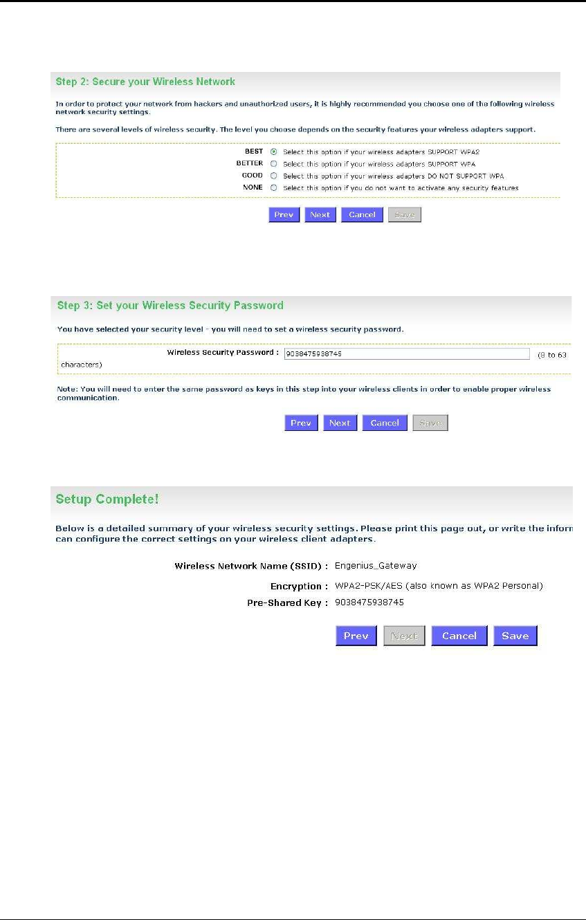
5.2.2.1 Wireless Security Level: BEST (WPA2)
Select the BEST radio button which supports WPA2 encryption. Then click on the
Next button.
Enter a security password between 2 and 20 characters then click on the Next button.
The setup is complete. Click on the Save button and then reboot the device.
ESR-9710 Wireless N Gigabit Router Version 1.0
29
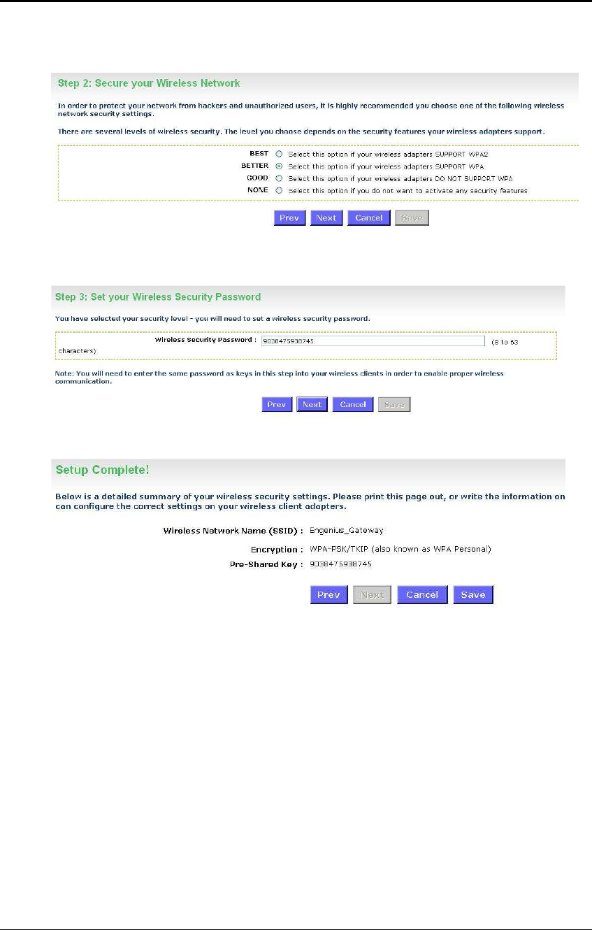
5.2.2.2 Wireless Security Level: BETTER (WPA)
Select the BETTER radio button which supports WPA encryption. Then click on the
Next button.
Enter a security password between 2 and 20 characters then click on the Next button.
The setup is complete. Click on the Save button and then reboot the device.
ESR-9710 Wireless N Gigabit Router Version 1.0
30
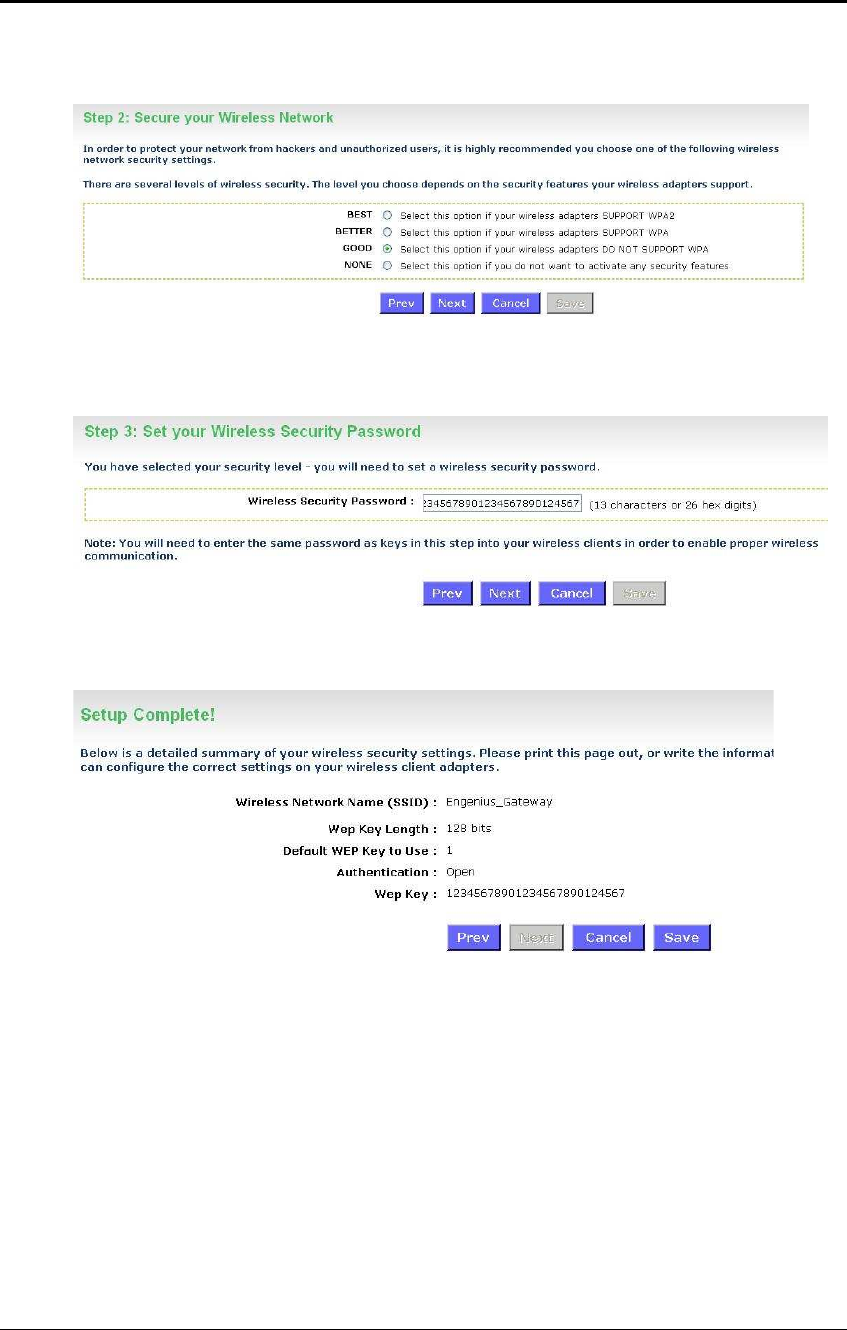
5.2.2.3 Wireless Security Level: GOOD (WEP 64/128-bit)
Select the GOOD radio button which supports WEP encryption. Then click on the
Next button.
Enter a security password between 2 and 20 characters then click on the Next button.
The setup is complete. Click on the Save button and then reboot the device.
ESR-9710 Wireless N Gigabit Router Version 1.0
31
5.2.2.4 Wireless Security Level: None (Security Disabled)
Select the NONE radio button if you do not want to activate any security features.
Then click on the Next button.
The setup is complete. Click on the Save button and then reboot the device.
ESR-9710 Wireless N Gigabit Router Version 1.0
32
6 Advanced Web Configuration
6.1 Logging In
To configure the device through the web-browser, enter the IP address of the Bridge
(default: 192.168.1.2) into the address bar of the web-browser and press Enter.
Make sure that the device and your computers are configured on the same subnet.
Refer to Chapter 2 in order to configure the IP address of your computer.
After connecting to the IP address, the web-browser will display the login page.
Select Admin from the drop-down list and then leave the password field blank.
After logging in you will graphical user interface (GUI) of the device. The navigation
drop-down menu on left is divided into six main sections:
1. Basic: This menu includes the wireless wizard, network settings, wireless settings,
and WAN settings.
2. Advanced: This menu includes virtual server, special applications, port forwarding,
routing, access control, web filter, MAC address filter, firewall, etc.
3. Tools: This menu includes time, firmware, system log, DDNS, schedules, etc.
4. Status: This menu displays the wireless status, logs, statistics, routing, and internet
sessions.
5. Help: Displays the help for configuring the device.
6. Logout: Used to logout of the device.

ESR-9710 Wireless N Gigabit Router Version 1.0
33
6.2 Basic
Click on the Basic link on the navigation drop-
down menu. You will then see four options:
Wizard_Wireless, Network Settings, Wireless
Settings, and WAN Settings.
I
6.2.1 Wizard_Wireless
Refer to Chapters 4 and 5 in order to use the wireless wizard. The other options are
described below.
6.2.2 Network Settings
This device can be configured at a Router or a Bridge. Select Router mode if the
WAN port is connected to the Internet. Select Bridge if the device is connected to a
local network downstream from another router.
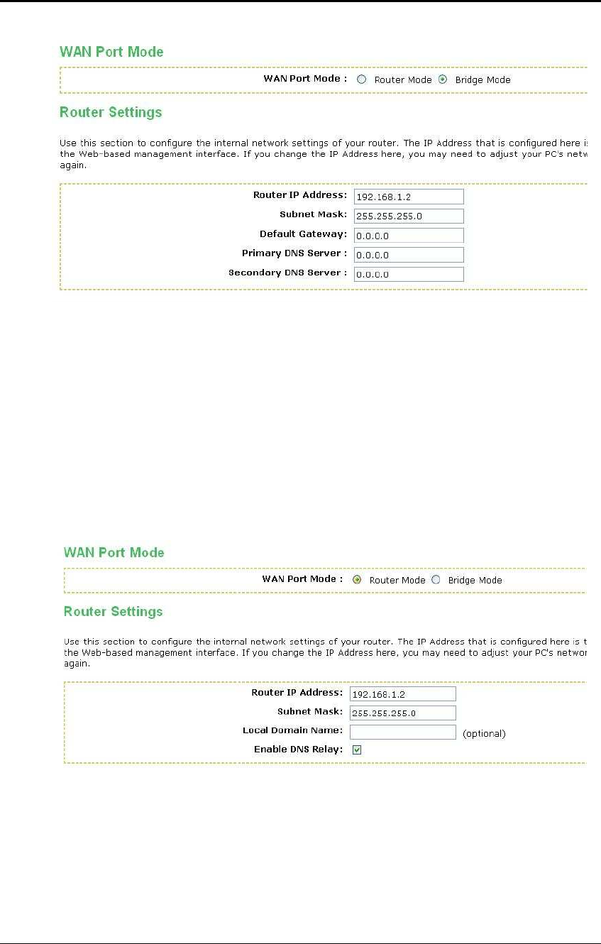
6.2.2.1 Bridge Mode
In this mode, the device functions as a bridge between the network on its WAN port
and the devices on its LAN port and those connected to it wirelessly. Select the
Bridge Mode radio button.
ESR-9710 Wireless N Gigabit Router Version 1.0
34
WAN Port Mode: Select the Bridge Mode radio button.
Router IP Address: Specify the IP address of this device.
Subnet Mask: Specify the subnet mask for the IP address.
Default Gateway: Specify the IP address of the upstream router.
Primary/Secondary DNS: Specify the IP address of the DNS server.
Click on the Save Changes button to store these settings.
6.2.2.2 Router Mode
In this mode, the device functions as a NAT router and is connected to the Internet.
Select the Router Mode radio button.
WAN Port Mode: Select the Router Mode radio button.
Router IP Address: Specify the IP address of this device
Subnet Mask: Specify the subnet mask for the IP address
Local Domain Name: This entry is optional. Enter a domain name for the local
network. LAN computers will assume this domain name when they get an address
from the router's built in DHCP server. So, for example, if you enter mynetwork.net
here, and you have a LAN side laptop with a name of chris, that laptop will be known
ESR-9710 Wireless N Gigabit Router Version 1.0
35
as chris.mynetwork.net. Note, however, the entered domain name can be overridden
by the one obtained from the router's upstream DHCP server.
Enable DNS Relay: Place a check in this box to enable the DNS relay feature. When
DNS Relay is enabled, the router plays the role of a DNS server. DNS requests sent
to the router are forwarded to the ISP's DNS server. This provides a constant DNS
address that LAN computers can use, even when the router obtains a different DNS
server address from the ISP upon re-establishing the WAN connection. You should
disable DNS relay if you implement a LAN-side DNS server as a virtual server.
Click on the Save Changes button to store these settings.
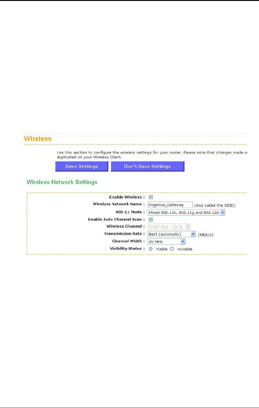
6.2.3 Wireless Settings
These options allow you to enable/disable the wireless interface, switch between the
11n, 11b/g and 11b radio band and channel frequency
Enable Wireless: Place a check in this box to enable the wireless interface, it is
enabled by default.
Wireless Network Name: The SSID is a unique named shared amongst all the
points of the wireless network. The SSID must be identical on all points of the
wireless network and cannot exceed 32 characters.
802.11 Mode: Select the IEEE 802.11 mode from the drop-down list. For example, if
you are sure that the wireless network will be using only IEEE 802.11g clients, then it
is recommended to select 802.11g only instead of 2.4 GHz B+G which will reduce
the performance of the wireless network. You may also select Mixed 802.11n,
802.11g and 802.11b. If all of the wireless devices you want to connect with this
router can connect in the same transmission mode, you can improve performance
slightly by choosing the appropriate "Only" mode. If you have some devices that use
a different transmission mode, choose the appropriate "Mixed" mode.
Wireless Channel: Select a channel from the drop-down list. The channels available
are based on the country’s regulation. A wireless network uses specific channels in
the wireless spectrum to handle communication between clients. Some channels in
your area may have interference from other electronic devices. Choose the clearest
channel to help optimize the performance and coverage of your wireless network.
ESR-9710 Wireless N Gigabit Router Version 1.0
36
Transmission Rate: Select a transmission rate from the drop-down list. It is
recommended to use the Best (automatic) option.
Channel Width: Select a channel width from the drop-down list.
Visibility Status: Select Visible or Invisible. This is the SSID broadcast feature.
When this option is set to Visible, your wireless network name is broadcast to
anyone within the range of your signal
. If you're not using encryption then they
could connect to your network. When Invisible mode is enabled, you must enter the
Wireless Network Name (SSID) on the client manually to connect to the network.
Show Active Clients: Click on this button to view a list of clients that are associated
with this device.
Click on the Save Changes button to store these settings.
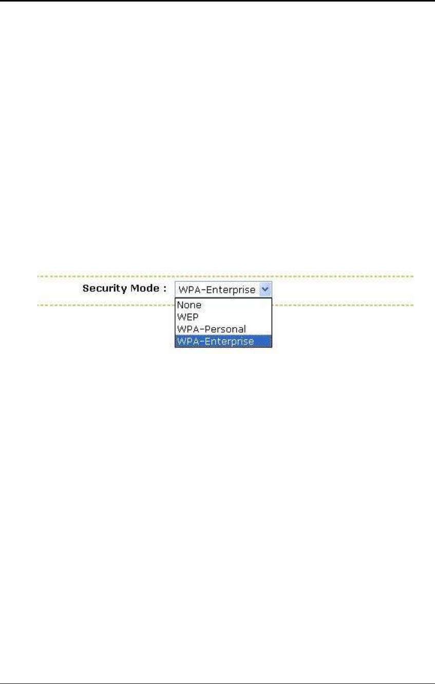
6.2.3.1 Wireless Security Mode
To protect your privacy this mode supports several types of wireless security: WEP
WPA, WPA2, and WPA-Mixed. WEP is the original wireless encryption standard.
WPA provides a higher level of security. The following section describes the security
configuration in detail.
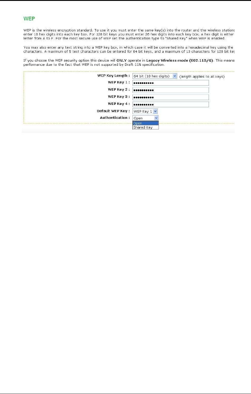
6.2.3.1.1 WEP (Wired Equivalent Privacy)
Select the WEP radio button if your wireless network uses WEP encryption. WEP is
an acronym for Wired Equivalent Privacy, and is a security protocol that provides the
same level of security for wireless networks as for a wired network.
WEP is not as secure as WPA encryption. To gain access to a WEP network, you
must know the key. The key is a string of characters that you create. When using
WEP, you must determine the level of encryption. The type of encryption determines
the key length. 128-bit encryption requires a longer key than 64-bit encryption. Keys
are defined by entering in a string in HEX (hexadecimal - using characters 0-9, A-F)
or ASCII (American Standard Code for Information Interchange - alphanumeric
characters) format. ASCII format is provided so you can enter a string that is easier
to remember. The ASCII string is converted to HEX for use over the network. Four
keys can be defined so that you can change keys easily. A default key is selected for
use on the network.
ESR-9710 Wireless N Gigabit Router Version 1.0
37
WEP Key Length: Select a 64-bit or 128-bit WEP key length from the drop-down list.
WEP Key 1-4: You may enter four different WEP keys.
Default WEP Key: You may use up to four different keys for four different networks.
Select the current key that will be used.
Authentication: Select Open, or Shared Key. Authentication method from the drop-
down list. An open system allows any client to authenticate as long as it conforms to
any MAC address filter policies that may have been set. All authentication packets
are transmitted without encryption. Shared Key sends an unencrypted challenge text
string to any device attempting to communicate with the AP. The device requesting
authentication encrypts the challenge text and sends it back to the access point. If
the challenge text is encrypted correctly, the access point allows the requesting
device to authenticate. It is recommended to select Auto if you are not sure which
authentication type is used.
Click on the Save Changes button to store these settings.
6.2.3.1.2 WPA Personal (Wi-Fi Protected Access)
Select the WPA-Personal radio button if your wireless network uses WPA encryption.
WPA (Wi-Fi Protected Access) was designed to improve upon the security features
of WEP (Wired Equivalent Privacy). The technology is designed to work with existing
Wi-Fi products that have been enabled with WEP. WPA provides improved data
encryption through the Temporal Integrity Protocol (TKIP), which scrambles the keys
using a hashing algorithm and by adding an integrity checking feature which makes
sure that keys haven’t been tampered with.

ESR-9710 Wireless N Gigabit Router Version 1.0
38
WPA Mode: Select the Auto WPA / WPA2 from the drop-down list.
Cipher Type: Select TKIP and AES as the cipher suite. The encryption algorithm
used to secure the data communication. TKIP. Use TKIP only. TKIP (Temporal Key
Integrity Protocol) provides per-packet key generation and is based on WEP. AES.
Use AES only. AES (Advanced Encryption Standard) is a very secure block based
encryption. Note that, if the bridge uses the AES option, the bridge can associate
with the access point only if the access point is also set to use only AES. TKIP and
AES. The bridge negotiates the cipher type with the access point, and uses AES
when available.
Group Key Update Interval: Specify the number of seconds before the group key
used for broadcast and multicast data is changed.
Pre-Shared Key: The key is entered as a pass-phrase of up to 63 alphanumeric
characters in ASCII (American Standard Code for Information Interchange) format at
both ends of the wireless connection. It cannot be shorter than eight characters,
although for proper security it needs to be of ample length and should not be a
commonly known phrase. This phrase is used to generate session keys that are
unique for each wireless client.
Click on the Save Changes button to store these settings.
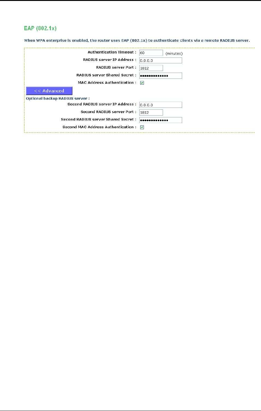
6.2.3.1.3 WPA Enterprise (Wi-Fi Protected Access & 802.1x)
Select the WPA-Enterprise radio button if your wireless network uses WPA
encryption. WPA (Wi-Fi Protected Access) was designed to improve upon the
security features of WEP (Wired Equivalent Privacy). The technology is designed to
work with existing Wi-Fi products that have been enabled with WEP. WPA provides
improved data encryption through the Temporal Integrity Protocol (TKIP), which
scrambles the keys using a hashing algorithm and by adding an integrity checking
feature which makes sure that keys haven’t been tampered with.
This option works with a RADIUS Server to authenticate wireless clients. Wireless
clients should have established the necessary credentials before attempting to
authenticate to the Server through this Gateway. Furthermore, it may be necessary
to configure the RADIUS Server to allow this Gateway to authenticate users.
ESR-9710 Wireless N Gigabit Router Version 1.0
39
WPA Mode: Select the WPA / WPA2 from the drop-down list.
Cipher Type: Select TKIP or AES as the cipher suite. The encryption algorithm used
to secure the data communication. TKIP. Use TKIP only. TKIP (Temporal Key
Integrity Protocol) provides per-packet key generation and is based on WEP. AES.
Use AES only. AES (Advanced Encryption Standard) is a very secure block based
encryption. Note that, if the bridge uses the AES option, the bridge can associate
with the access point only if the access point is also set to use only AES. TKIP and
AES. The bridge negotiates the cipher type with the access point, and uses AES
when available.
Group Key Update Interval: Specify the number of seconds before the group key
used for broadcast and multicast data is changed.
Authentication Timeout: Specify the number of minutes after which the client will be
required to re-authenticate.
RADIUS Server IP Address: Specify the IP address of the RADIUS server.
RADIUS Server Port: Specify the port number of the RADIUS server, the default
port is 1812.
RADIUS Server Shared Secret: Specify the pass-phrase that is matched on the
RADIUS Server.
MAC Address Authentication: Place a check in this box if you would like the user
to always authenticate using the same computer.
Optional Backup RADIUS server: This option enables configuration of an optional
second RADIUS server. A second RADIUS server can be used as backup for the
primary RADIUS server. The second RADIUS server is consulted only when the
primary server is not available or not responding.
Click on the Save Changes button to store these settings.
ESR-9710 Wireless N Gigabit Router Version 1.0
40
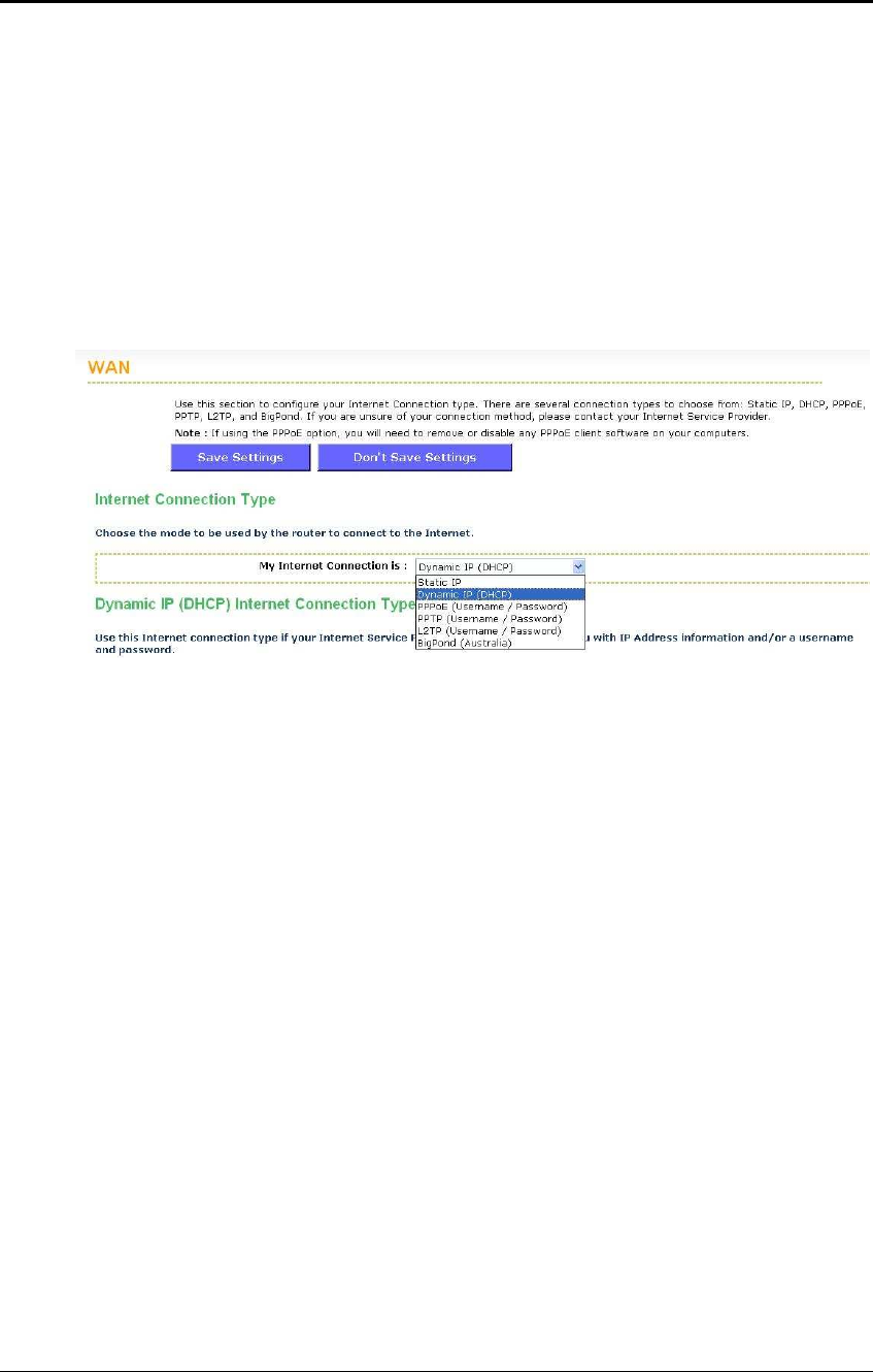
6.2.4 WAN Settings
The device offers several types of WAN connections in order to connect to the
Internet.
o Static IP Address
o Dynamic IP Address
o PPPoE
o PPTP
o L2TP
o BigPond
Select the type of Internet Connection from the drop-down list.
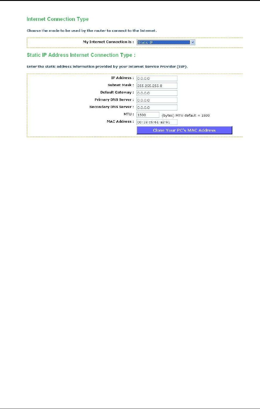
6.2.4.1 Static IP Address Configuration
The WAN interface can be configured as Static IP address. In this type of connection,
your ISP provides you with a dedicated IP address (which does not change as
DHCP).
Select the Static IP from the My Internet Connection drop-down list.
ESR-9710 Wireless N Gigabit Router Version 1.0
41
IP Address: Specify the IP address for this device, which is assigned by your ISP.
Subnet Mask: Specify the subnet mask for this IP address, which is assigned by
your ISP.
Default Gateway: Specify the IP address of the default gateway, which is assigned
by your ISP.
Primary / Secondary DNS Address: Specify the primary and secondary IP address,
which is assigned by your ISP.
MTU: The Maximum Transmission Unit (MTU) is a parameter that determines the
largest packet size (in bytes) that the router will send to the WAN. If LAN devices
send larger packets, the router will break them into smaller packets. Ideally, you
should set this to match the MTU of the connection to your ISP. Typical values are
1500 bytes for an Ethernet connection and 1492 bytes for a PPPoE connection. If the
router's MTU is set too high, packets will be fragmented downstream. If the router's
MTU is set too low, the router will fragment packets unnecessarily and in extreme
cases may be unable to establish some connections. In either case, network
performance can suffer.
MAC Address: If you need to change the MAC address of the rounter's WAN-side
Ethernet interface, either type in an alternate MAC address (for example, the MAC
address of the router initially connected to the ISP) or click on Clone Your PCs MAC
Address.
Click on the Save Settings button to store these settings.
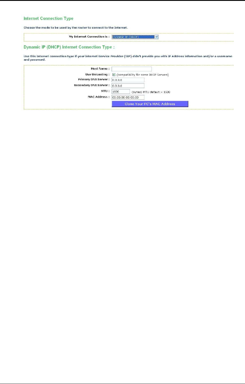
6.2.4.2 DHCP Connection (Dynamic IP Address)
The WAN interface can be configured as a DHCP Client in which the ISP provides
the IP address to the device. This is also known as Dynamic IP.
Select the Dynamic IP (DHCP) from the My Internet Connection drop-down list.
ESR-9710 Wireless N Gigabit Router Version 1.0
42
Host Name: Specify a host name to define your system or connetion.
Use Unicasting: This option is normally turned off, and should remain off as long as
the WAN-side DHCP server correctly provides an IP address to the router. However,
if the router cannot obtain an IP address from the DHCP server, the DHCP server
may be one that works better with unicast responses. In this case, turn the unicasting
option on, and observe whether the router can obtain an IP address. In this mode,
the router accepts unicast responses from the DHCP server instead of broadcast
responses.
Primary / Secondary DNS Address: Specify the primary and secondary IP address,
which is assigned by your ISP.
MTU: The Maximum Transmission Unit (MTU) is a parameter that determines the
largest packet size (in bytes) that the router will send to the WAN. If LAN devices
send larger packets, the router will break them into smaller packets. Ideally, you
should set this to match the MTU of the connection to your ISP. Typical values are
1500 bytes for an Ethernet connection and 1492 bytes for a PPPoE connection. If the
router's MTU is set too high, packets will be fragmented downstream. If the router's
MTU is set too low, the router will fragment packets unnecessarily and in extreme
cases may be unable to establish some connections. In either case, network
performance can suffer.
MAC Address: If you need to change the MAC address of the rounter's WAN-side
Ethernet interface, either type in an alternate MAC address (for example, the MAC
address of the router initially connected to the ISP) or click on Clone Your PCs MAC
Address.
Click on the Save Settings button to store these settings.
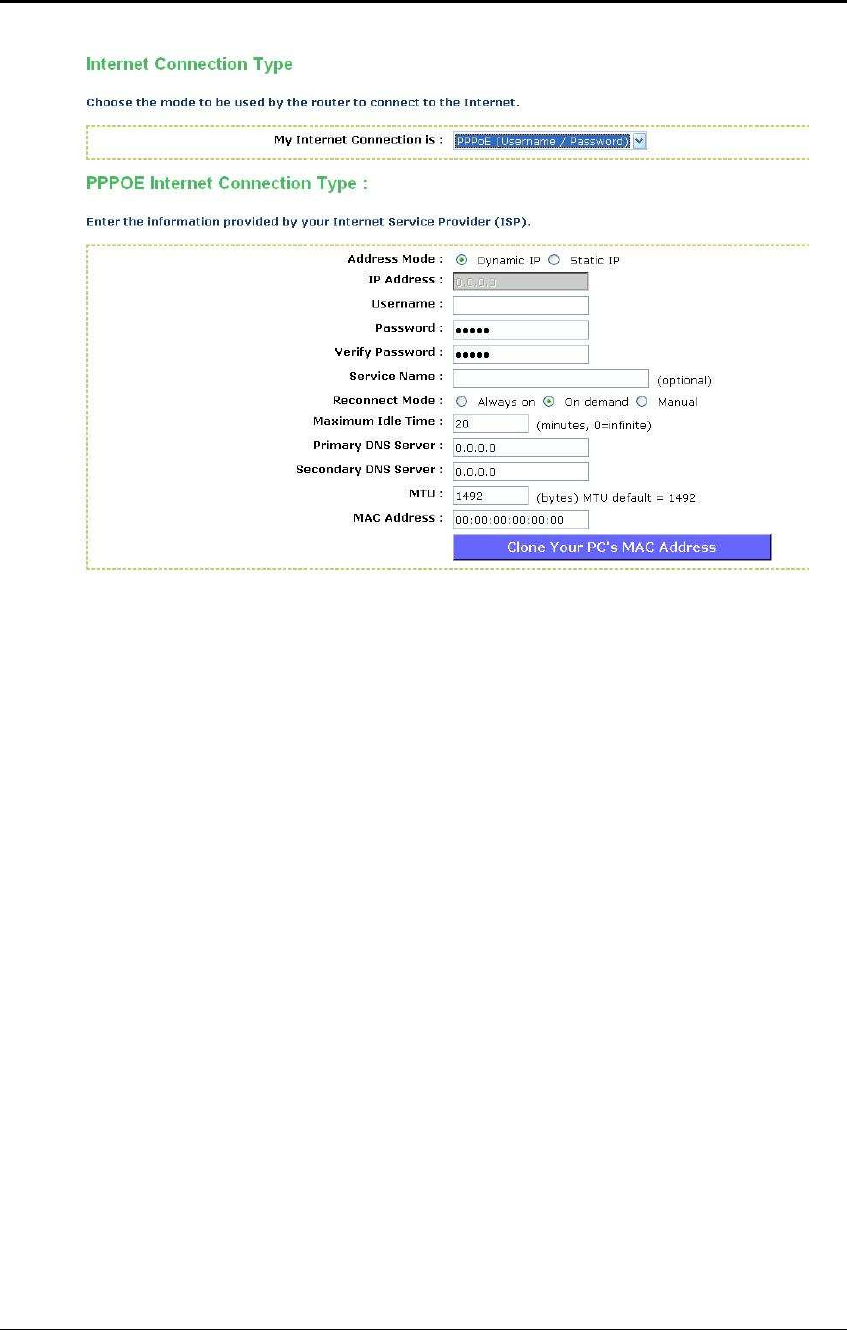
6.2.4.3 PPPoE (Point-to-Point Protocol over Ethernet)
The WAN interface can be configured as PPPoE. This type of connection is usually
used for a DSL service and requires a username and password to connect.
Select the PPPoE from the My Internet Connection drop-down list.
ESR-9710 Wireless N Gigabit Router Version 1.0
43
Address Mode: PPPoE can be used with a dynamic or static IP address. If you
select the Dynamic IP radio button, then the IIP address in the next field is not
required. However, if you select the Static IP radio button, then the IP address in the
next field is required.
User Name: Specify the user name which is provided by your ISP.
Password: Specify the password which is provided by your ISP, and then verify it
once again in the next field.
Service Name: Specify the name of the ISP.
Reconnect Mode: Select a reconnection time: Always on (A connection to the
Internet is always maintained), On demand (A connection to the Internet is made as
needed), Manual: You have to open up the Web-based management interface and
click the Connect button manually any time that you wish to connect to the Internet.
Maximum Idle Time:
Primary / Secondary DNS Address: Specify the primary and secondary IP address,
which is assigned by your ISP.
MTU: The Maximum Transmission Unit (MTU) is a parameter that determines the
largest packet size (in bytes) that the router will send to the WAN. If LAN devices
send larger packets, the router will break them into smaller packets. Ideally, you
should set this to match the MTU of the connection to your ISP. Typical values are
1500 bytes for an Ethernet connection and 1492 bytes for a PPPoE connection. If the
router's MTU is set too high, packets will be fragmented downstream. If the router's
MTU is set too low, the router will fragment packets unnecessarily and in extreme
cases may be unable to establish some connections. In either case, network
performance can suffer.
MAC Address: If you need to change the MAC address of the rounter's WAN-side
Ethernet interface, either type in an alternate MAC address (for example, the MAC
address of the router initially connected to the ISP) or click on Clone Your PCs MAC
Address.
Click on the Save Settings button to store these settings.
ESR-9710 Wireless N Gigabit Router Version 1.0
44
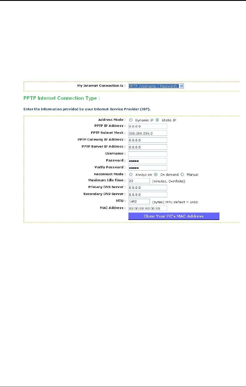
6.2.4.4 PPTP (Point-to-Point Tunneling Protocol)
The WAN interface can be configured as PPTP. PPTP (Point to Point Tunneling
Protocol) uses a virtual private network to connect to your ISP. This method of
connection is primarily used in Europe. This method of connection requires you to
enter a username and password (provided by your ISP) to gain access to the Internet.
The supported authentication protocols are PAP and CHAP.
Select the PPTP from the My Internet Connection drop-down list.
Address Mode: PPTP can be used with a dynamic or static IP address. If you select
the Dynamic IP radio button, then the IIP address in the next field is not required.
However, if you select the Static IP radio button, then the IP address in the next field
is required.
PPTP Address: Specify the IP address
PPTP Subnet Mask: Specify the subnet mask for the IP address.
PPTP Gateway IP Address: Specify the IP address of the PPTP gateway.
PPTP Server IP Address: If the PPTP Server’s IP address is different from the
default gateway, then you may specify it here.
User Name: Specify the user name which is provided by your ISP.
Password: Specify the password which is provided by your ISP, and then verify it
once again in the next field.
Reconnect Mode: Select a reconnection time: Always on (A connection to the
Internet is always maintained), On demand (A connection to the Internet is made as
needed), Manual: You have to open up the Web-based management interface and
click the Connect button manually any time that you wish to connect to the Internet.
Maximum Idle Time:
Primary / Secondary DNS Address: Specify the primary and secondary IP address,
which is assigned by your ISP.
MTU: The Maximum Transmission Unit (MTU) is a parameter that determines the
largest packet size (in bytes) that the router will send to the WAN. If LAN devices
ESR-9710 Wireless N Gigabit Router Version 1.0
45
send larger packets, the router will break them into smaller packets. Ideally, you
should set this to match the MTU of the connection to your ISP. Typical values are
1500 bytes for an Ethernet connection and 1492 bytes for a PPPoE connection. If the
router's MTU is set too high, packets will be fragmented downstream. If the router's
MTU is set too low, the router will fragment packets unnecessarily and in extreme
cases may be unable to establish some connections. In either case, network
performance can suffer.
MAC Address: If you need to change the MAC address of the rounter's WAN-side
Ethernet interface, either type in an alternate MAC address (for example, the MAC
address of the router initially connected to the ISP) or click on Clone Your PCs MAC
Address.
Click on the Save Settings button to store these settings.
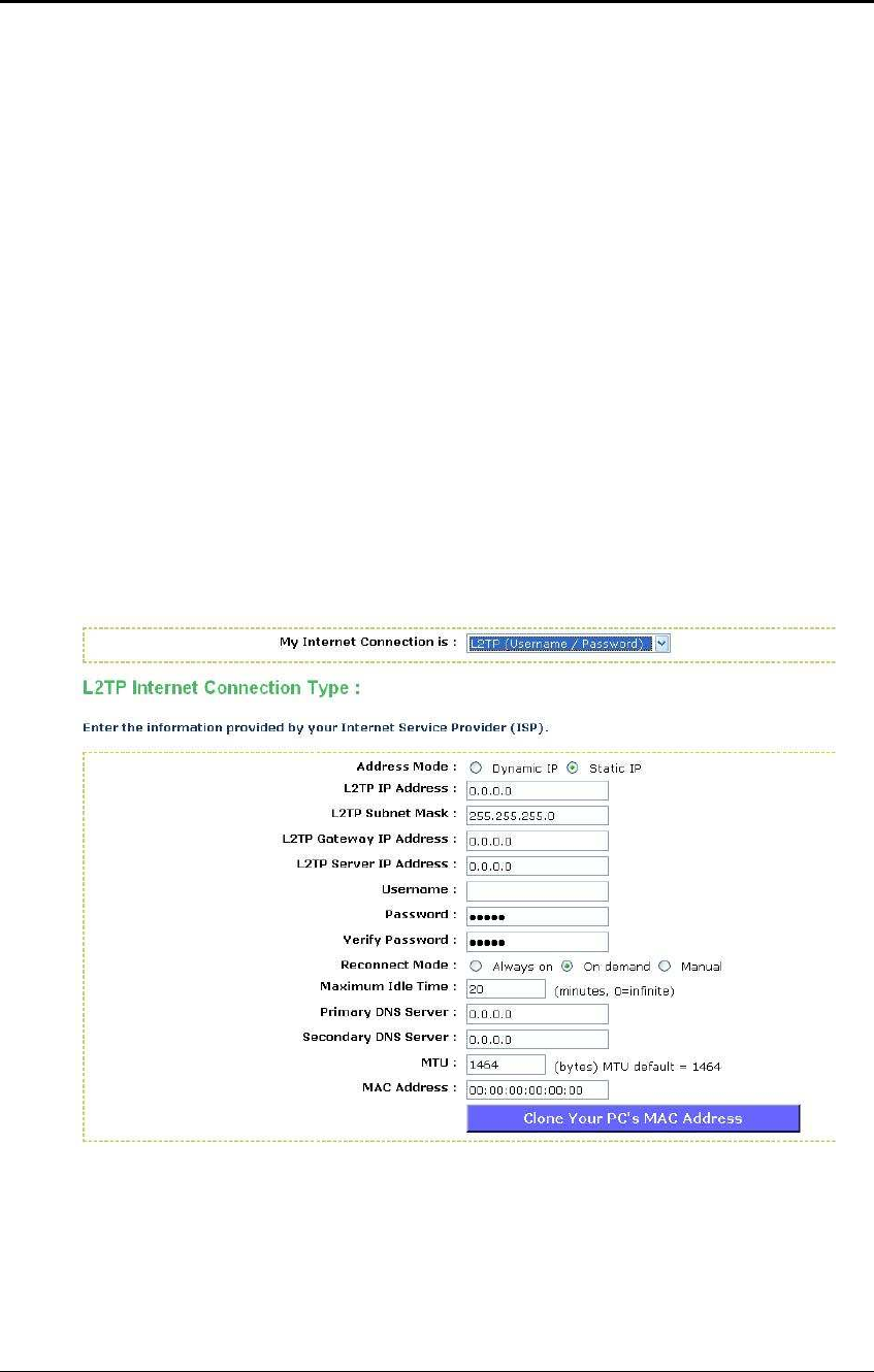
6.2.4.5 L2TP (Layer 2 Tunneling Protocol)
The WAN interface can be configured as L2TP. L2TP (Layer Two Tunneling Protocol)
uses a virtual private network to connect to your ISP. This method of connection
requires you to enter a user name and password (provided by your Internet Service
Provider) to gain access to the Internet. The supported authentication protocols are
PAP and CHAP.
Select the L2TP from the My Internet Connection drop-down list.
Address Mode: L2TP can be used with a dynamic or static IP address. If you select
the Dynamic IP radio button, then the IIP address in the next field is not required.
However, if you select the Static IP radio button, then the IP address in the next field
is required.
L2TP Address: Specify the IP address
L2TP Subnet Mask: Specify the subnet mask for the IP address.
L2TP Gateway IP Address: Specify the IP address of the L2TP gateway.

ESR-9710 Wireless N Gigabit Router Version 1.0
46
L2TP Server IP Address: If the L2TP Server’s IP address is different from the
default gateway, then you may specify it here.
User Name: Specify the user name which is provided by your ISP.
Password: Specify the password which is provided by your ISP, and then verify it
once again in the next field.
Reconnect Mode: Select a reconnection time: Always on (A connection to the
Internet is always maintained), On demand (A connection to the Internet is made as
needed), Manual: You have to open up the Web-based management interface and
click the Connect button manually any time that you wish to connect to the Internet.
Maximum Idle Time:
Primary / Secondary DNS Address: Specify the primary and secondary IP address,
which is assigned by your ISP.
MTU: The Maximum Transmission Unit (MTU) is a parameter that determines the
largest packet size (in bytes) that the router will send to the WAN. If LAN devices
send larger packets, the router will break them into smaller packets. Ideally, you
should set this to match the MTU of the connection to your ISP. Typical values are
1500 bytes for an Ethernet connection and 1492 bytes for a PPPoE connection. If the
router's MTU is set too high, packets will be fragmented downstream. If the router's
MTU is set too low, the router will fragment packets unnecessarily and in extreme
cases may be unable to establish some connections. In either case, network
performance can suffer.
MAC Address: If you need to change the MAC address of the rounter's WAN-side
Ethernet interface, either type in an alternate MAC address (for example, the MAC
address of the router initially connected to the ISP) or click on Clone Your PCs MAC
Address.
Click on the Save Settings button to store these settings.
6.2.5 BigPond
The WAN interface can be configured as BigPong. This type of service is used
through Telstra BigPond Cable Broadband in Australia
Select the BigPond from the My Internet Connection drop-down list.

ESR-9710 Wireless N Gigabit Router Version 1.0
47
BingPond Server: Specify the server name or IP address as specified by your ISP.
User Name: Specify the user name which is provided by your ISP.
Password: Specify the password which is provided by your ISP, and then verify it
once again in the next field.
Primary / Secondary DNS Address: Specify the primary and secondary IP address,
which is assigned by your ISP.
MTU: The Maximum Transmission Unit (MTU) is a parameter that determines the
largest packet size (in bytes) that the router will send to the WAN. If LAN devices
send larger packets, the router will break them into smaller packets. Ideally, you
should set this to match the MTU of the connection to your ISP. Typical values are
1500 bytes for an Ethernet connection and 1492 bytes for a PPPoE connection. If the
router's MTU is set too high, packets will be fragmented downstream. If the router's
MTU is set too low, the router will fragment packets unnecessarily and in extreme
cases may be unable to establish some connections. In either case, network
performance can suffer.
MAC Address: If you need to change the MAC address of the rounter's WAN-side
Ethernet interface, either type in an alternate MAC address (for example, the MAC
address of the router initially connected to the ISP) or click on Clone Your PCs MAC
Address.
Click on the Save Settings button to store these settings.
ESR-9710 Wireless N Gigabit Router Version 1.0
48
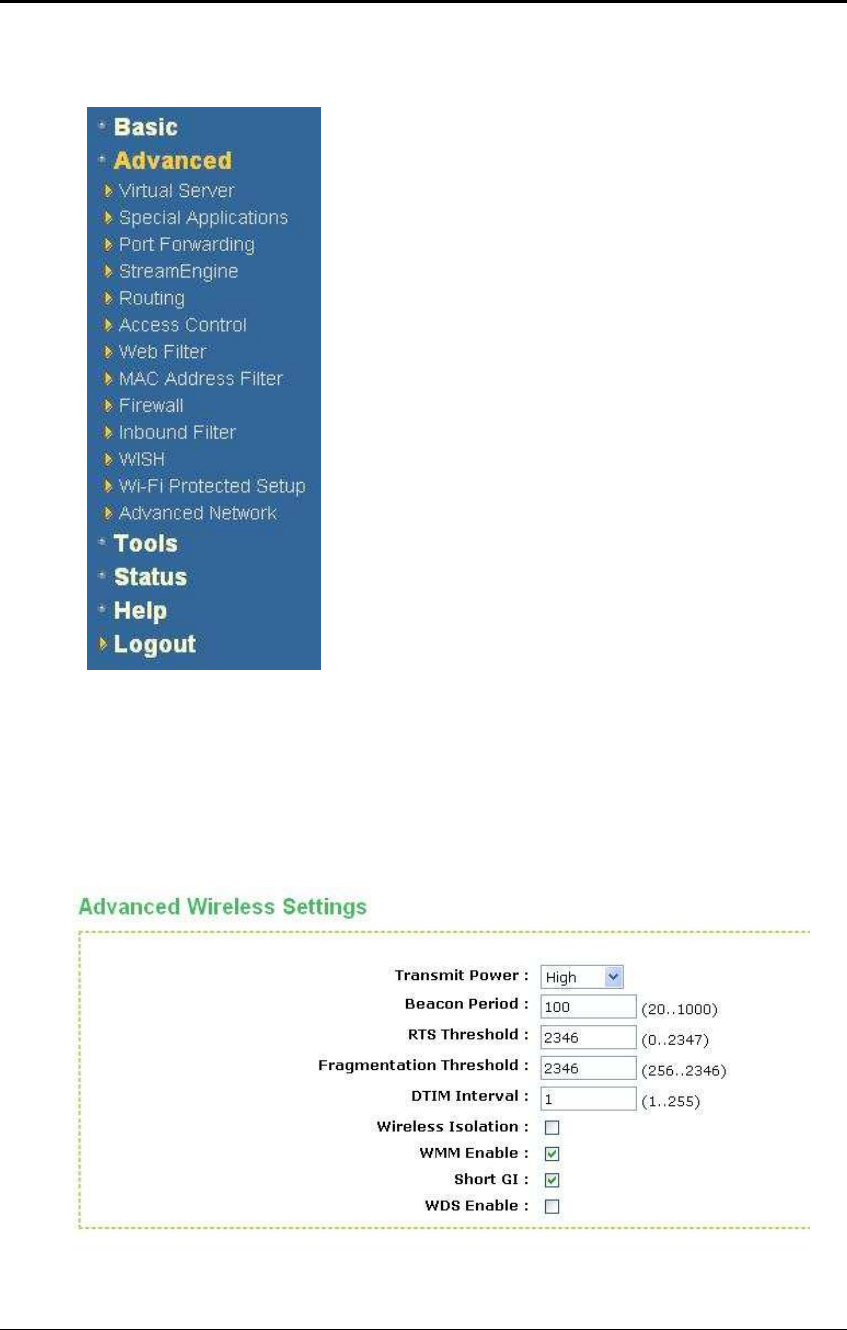
6.3 Advanced
Click on the Advanced link on the navigation
drop-down menu. You will then see thirteen
options: Virtual Server, Special Applications,
Port Forwarding, StreamEngine, Routing,
Access Control, Web Filter, MAC Address
Filter, Firewall, Inbound Filter, WISH, Wi-Fi
Protected Setup and Advanced Network. The
configuration steps for each option are
described below.
6.3.1 Advanced Wireless
This page allows you to configure the fragmentation threshold, RTS threshold,
beacon period, transmit power, DTIM interval, wireless isolation, WMM, and WDS
(wireless distribution system).

ESR-9710 Wireless N Gigabit Router Version 1.0
49
Transmit Power: You may control the output power of the device by selecting a
value from the drop-down list. This feature can be helpful in restricting the coverage
area of the wireless network.
Beacon Period: Beacons are packets sent by a wireless Access Point to
synchronize wireless devices. Specify a Beacon Period value between 20 and 1000.
The default value is set to 100 milliseconds.
RTS Threshold: Packets over the specified size will use the RTS/CTS mechanism to
maintain performance in noisy networks and preventing hidden nodes from
degrading the performance. Specify a value between 1 and 65535. The default value
is 2346.
Fragment Threshold: Packets over the specified size will be fragmented in order to
improve performance on noisy networks. Specify a value between 256 and 65535.
The default value is 2346.
DTIM Interval: A DTIM is a countdown informing clients of the next window for
listening to broadcast and multicast messages. When the wireless Access Point has
buffered broadcast or multicast messages for associated clients, it sends the next
DTIM with a DTIM Interval value. Wireless clients detect the beacons and awaken to
receive the broadcast and multicast messages. The default value is 1. Valid settings
are between 1 and 255.
Wireless Isolation: Place a check in this box in order to prevent associated wireless
clients from communicating with each other.
WMM Enable: Enable WMM in order to help control latency and jitter when
transmitting multimedia content over a wireless connection.
WDS: Place a check in this box to enable WDS (Wireless Distribution System).
When WDS is enabled, this access point functions as a wireless repeater and is able
to wirelessly communicate with other APs via WDS links.
Note that WDS is incompatible with WPA -- both features cannot be used at the
same time. A WDS link is bidirectional; so this AP must know the MAC Address
(creates the WDS link) of the other AP, and the other AP must have a WDS link back
to this AP. Make sure the APs are configured with same channel number.
WDS AP MAC Address: Specify one-half of the WDS link. The other AP must also
have the MAC address of this AP to create the WDS link back to this AP.
Click on the Save Settings button to store these changes.
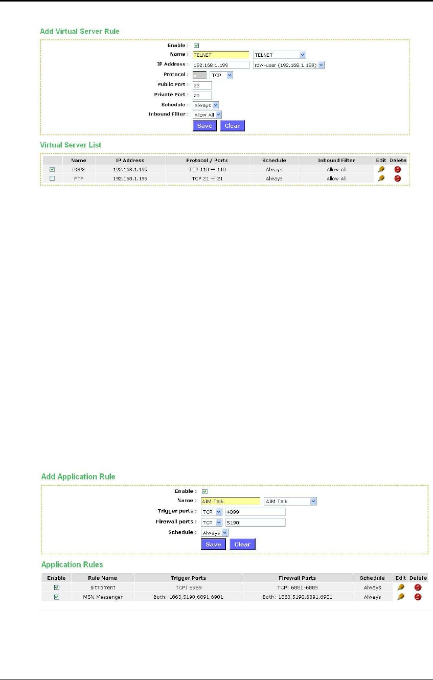
6.3.2 Virtual Server
The Virtual Server option gives Internet users access to services on your LAN. This
feature is useful for hosting online services such as FTP, Web, or game servers. For
each Virtual Server, you define a public port on your router for redirection to an
internal LAN IP Address and LAN port.
ESR-9710 Wireless N Gigabit Router Version 1.0
50
Enable: Place a check in this box to enable the virtual server rule.
Name: Assign a meaningful name to the virtual server, for example Web Server.
Several well-known types of virtual server are available from the Application Name
drop-down list. Selecting one of these entries fills some of the remaining parameters
with standard values for that type of server.
IP Address: Specify the IP address for the virtual server entry.
Protocol: Specify a protocol or select one from the drop-down list.
Public Port: Specify the public port number.
Private Port: Specify the private port number.
Schedule: Select a schedule, Always, or Never from the drop-down list. If a
schedule does not exist, you may create it in the Tools > Schedule section.
Inbound Filter: Select an inbound filter from the drop-down list. If an inbound filter
does not exist, you may create it from Advanced > Inbound Filter section.
Click on the Save button to insert the entry into the Virtual Server list.
6.3.3 Special Applications
An application rule is used to open single or multiple ports on your router when the
router senses data sent to the Internet on a trigger port or port range. An application
rule applies to all computers on your internal network.
Enable: Place a check in this box to enable the special application rule.
Name: Assign a meaningful name to the virtual server, for example Web Server.
Several well-known types of virtual server are available from the Application Name
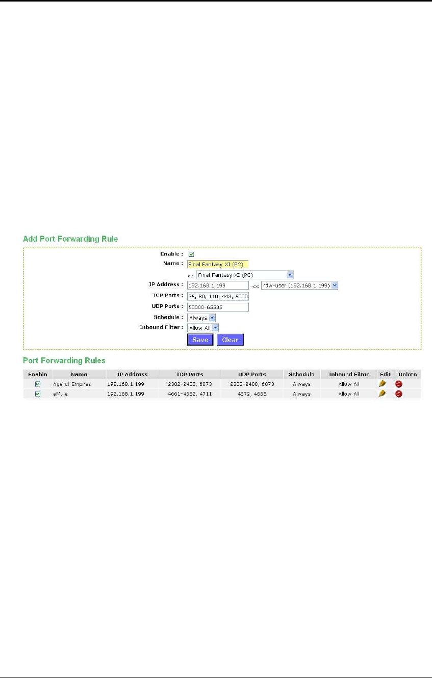
ESR-9710 Wireless N Gigabit Router Version 1.0
51
drop-down list. Selecting one of these entries fills some of the remaining parameters
with standard values for that type of server.
Triggering Ports: Specify the outgoing port range that is used by the application.
Firewall Ports: Specify the prot range that you would like to open for Internet traffic.
Schedule: Select a schedule, Always, or Never from the drop-down list. If a
schedule does not exist, you may create it in the Tools > Schedule section.
Click on the Save button to insert the entry into the Special Applications list.
6.3.4 Port Forwarding
Multiple connections are required by some applications, such as internet games,
video conferencing, Internet telephony, and others. These applications have
difficulties working through NAT (Network Address Translation). This section is used
to open multiple ports or a range of ports in your router and redirect data through
those ports to a single PC on your network.
Enable: Place a check in this box to enable the port forwarding rule.
Name: Assign a meaningful name to the virtual server, for example Web Server.
Several well-known types of virtual server are available from the Application Name
drop-down list. Selecting one of these entries fills some of the remaining parameters
with standard values for that type of server.
IP Address: Specify the IP address for the virtual server entry.
TCP/UDP Ports: Specify the TCP or UDP port numbers.
Schedule: Select a schedule, Always, or Never from the drop-down list. If a
schedule does not exist, you may create it in the Tools > Schedule section.
Inbound Filter: Select an inbound filter from the drop-down list. If an inbound filter
does not exist, you may create it from Advanced > Inbound Filter section.
Click on the Save button to insert the entry into the Port Forwarding list.
6.3.5 StreamEngine
The StreamEngine feature helps improve the network performance by prioritizing
applications.

ESR-9710 Wireless N Gigabit Router Version 1.0
52
Enable Traffic Shaping: Place a check in the box to enable traffic shaping. When
this option is enabled, the router restricts the flow of outbound traffic so as not to
exceed the WAN uplink bandwidth.
Automatic Uplink Speed. Place a check in this box to enable automatic uplink
speed. When enabled, this option causes the router to automatically measure the
useful uplink bandwidth each time the WAN interface is re-established (after a reboot,
for example).
Measured Uplink Speed: Displays the uplink speed. This is the uplink speed
measured when the WAN interface was last re-established. The value may be lower
than that reported by your ISP as it does not include all of the network protocol
overheads associated with your ISP's network. Typically, this figure will be between
87% and 91% of the stated uplink speed for xDSL connections and around 5 kbps
lower for cable network connections.
Manual Uplink Speed: Specify an uplink speed or select it from the drop-down list.
If
Automatic Uplink Speed is disabled, this options allows you to set the uplink
speed manually. Uplink speed is the speed at which data can be transferred from
the router to your ISP.
Connection Type: By default, the router automatically determines whether the
underlying connection is an xDSL/Frame-relay network or some other connection
type (such as cable modem or Ethernet), and it displays the result as Detected xDSL
or Frame Relay Network. If you have an unusual network connection in which you
are actually connected via xDSL but for which you configure either Static or DHCP in
the WAN settings, setting this option to xDSL or Other Frame Relay Network ensures
that the router will recognize that it needs to shape traffic slightly differently in order
to give the best performance. Choosing xDSL or Other Frame Relay Network causes
the measured uplink speed to be reported slightly lower than before on such
connections, but gives much better results.
Click on the Save Settings button to store these settings.
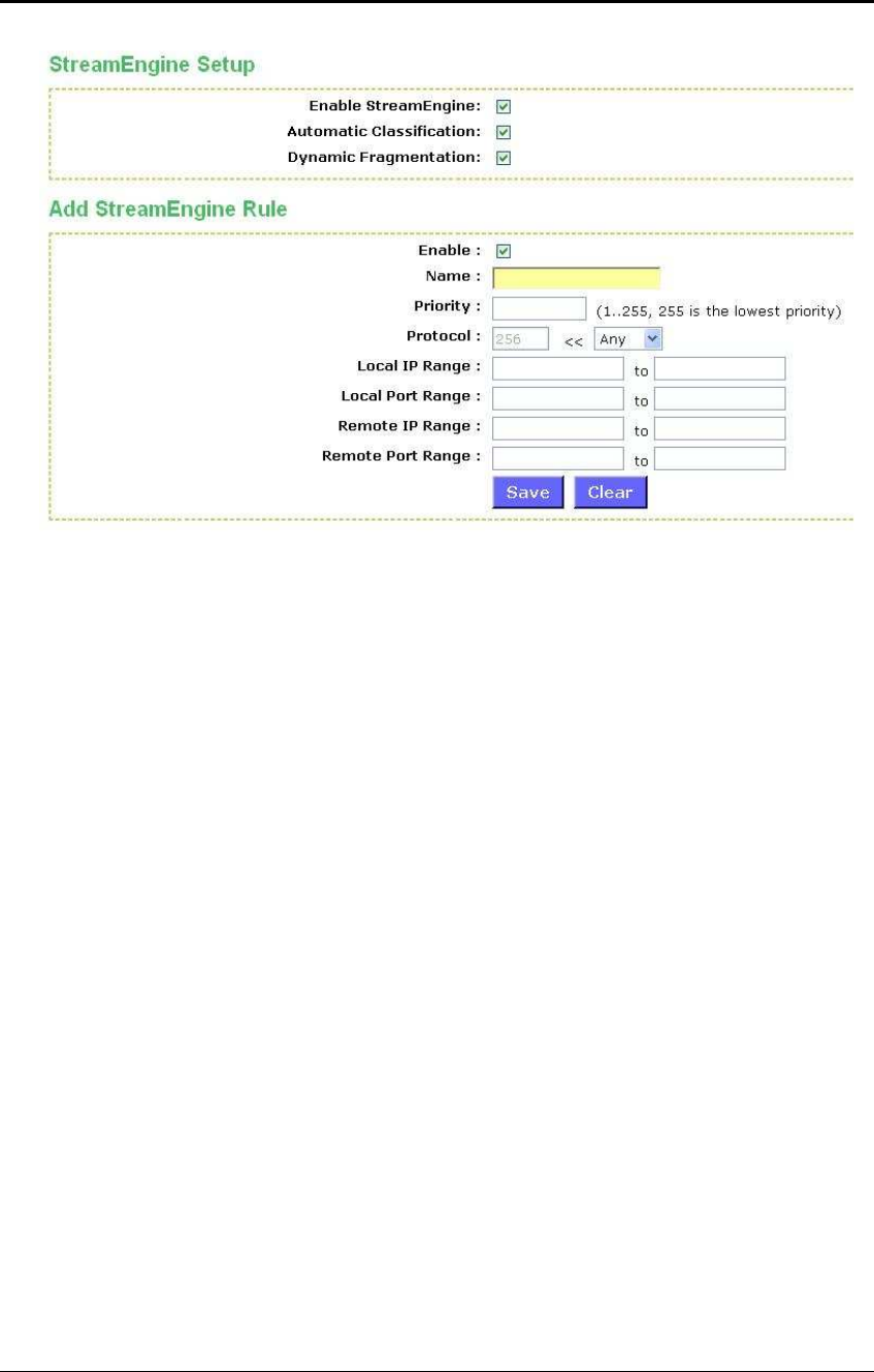
ESR-9710 Wireless N Gigabit Router Version 1.0
53
Enable StreamEngine: Place a check in this box to enable this option. Enable this
option for better performance and experience with online games and other interactive
applications, such as VoIP.
Automatic Classification: Place a check in this box to enable this option. This
option is enabled by default so that your router will automatically determine which
programs should have network priority.
Dynamic Fragmentation: Place a check in this box to enable this option. This option
should be enabled when you have a slow Internet uplink. It helps to reduce the
impact that large low priority network packets can have on more urgent ones by
breaking the large packets into several smaller packets.
Add StreamEngine Rule: A StreamEngine Rule identifies a specific message flow
and assigns a priority to that flow. For most applications, automatic classification will
be adequate, and specific StreamEngine Rules will not be required. StreamEngine
supports overlaps between rules, where more than one rule can match for a specific
message flow. If more than one rule is found to match the rule with the highest
priority will be used.
Enable: Place a check in this box to enable the StreamEngine rule.
Name: Specify a name for the rule.
Priority: Specify a priority for the rule. 0 being the highest and 255 the lowest priority.
Protocol: Specify a protocol or select one from the drop-down list.
Local IP Range: Specify the local (LAN) IP address range.
Local Port Range: Specify the local (LAN) port range.
Remote IP Range: Specify the remote (WAN) IP address range.
Remote Port Range: Specify the remote (WAN) port range.
Click on the Save button to insert the entry into the StreamEngine list.

ESR-9710 Wireless N Gigabit Router Version 1.0
54
6.3.6 Routing
This section adds a new entry into the routing table.
Enable: Place a check in this box to enable the routing table entry.
Name: Specify a name for the rule.
Destination IP: Specify the destination IP address.
Netmask: Specify the subnet mask for the IP address.
Gateway: Specify the IP address of the gateway.
Metric: Specify the number of routing hops. The route metric is a value from 1 to 16
that indicates the cost of using this route. A value of 1 is the lowest cost, and 15 is
the highest cost. A value of 16 indicates that the route is not reachable from this
router. When trying to reach a particular destination, computers on your network will
select the best route, ignoring unreachable routes.
Interface: Select the interface from the drop-down list.
Click on the Save button to insert the entry into the Routing table.
6.3.7 Access Control
The Access Control section allows you to control access in and out of devices on
your network. Use this feature as Parental Controls to only grant access to approved
sites, limit web access based on time or dates, and/or block access from applications
such as peer-to-peer utilities or games.
When Access Control is disabled, every device on the LAN has unrestricted access
to the Internet. However, if you enable Access Control, Internet access is restricted
for those devices that have an Access Control Policy configured for them. All other
devices have unrestricted access to the Internet.
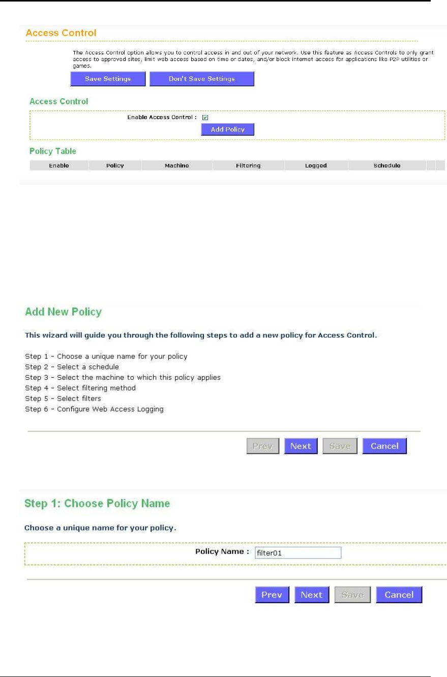
ESR-9710 Wireless N Gigabit Router Version 1.0
55
Place a check in the Enable Access Control check box and then click on the Add
Policy button. This will bring up the Add New Policy wizard.
The wireless wizard will inform you that there are six major steps in the process.
o Choose a unique name for your policy
o Select a schedule
o Select the machine to which the policy applies
o Select filtering method
o Configure web access logging
Click on the Next button to continue.
Specify a policy name and then click on the Next button to continue.
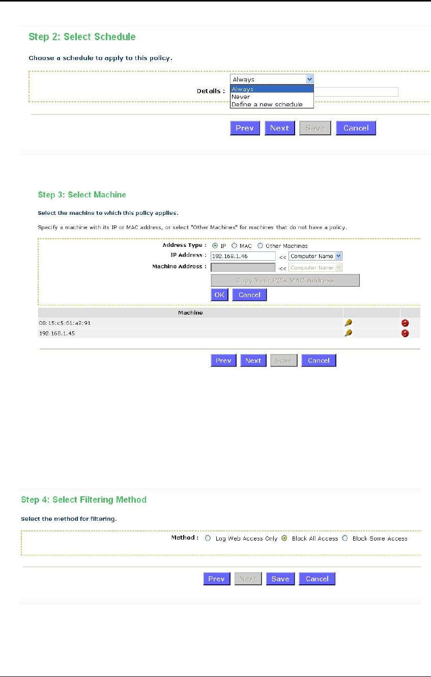
ESR-9710 Wireless N Gigabit Router Version 1.0
56
Select a schedule from the drop-down list: Always or Never, or you may define a
new schedule. Click on the Next button to continue.
Select a machine to which the policy applies.
Address Type: Select the IP address or MAC address radio button.
IP Address: If you selected IP address above, then specify the IP address here.
MAC Address: If you need to change the MAC address of the rounter's WAN-side
Ethernet interface, either type in an alternate MAC address (for example, the MAC
address of the router initially connected to the ISP) or click on Clone Your PCs MAC
Address.
Click on the OK button to insert the entry into the table.
Click on the Next button to continue.
Select a filtering method:
Log Web Access Only: Select this radio but in order to log web access.
Block All Access: Select this radio but in order to block all web access.
Block Some Access: Select this radio but in order to block some web access.
Click on the Save button to store the changes.
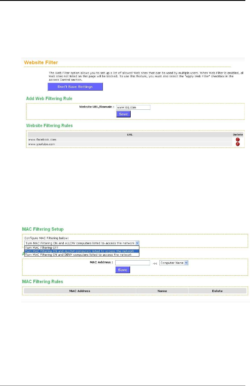
ESR-9710 Wireless N Gigabit Router Version 1.0
57
6.3.8 Web Filter
This is a type of parental control feature used to restrict certain websites form being
accessed through your network. These filters can be used for securing and restricting
your network.
Website/URL/Domain: Specify the web address that you would like to filter. Do not
use “http://”
Click on the Save button to store the changes.
6.3.9 MAC Address Filter
This feature is used to restrict certain MAC address from accessing the Internet.
These filters can be used for securing and restricting your network.
Configure MAC Filtering: Select one of the options from the drop-down list.
o Turn MAC Filtering OFF: When "OFF" is selected, MAC addresses are not
used to control network access.
o Turn MAC Filtering ON and ALLOW computers listed to access the
network: When "ALLOW" is selected, only computers with MAC addresses
listed in the MAC Filtering Rules list are granted network access.
o Turn MAC Filtering ON and DENY computers listed to access the
network: When "DENY" is selected, any computer with a MAC address listed
in the MAC Filtering Rules list is refused access to the network.
MAC Address: Specify that MAC address that you would like to filter.
Click on the Save button to store the changes.
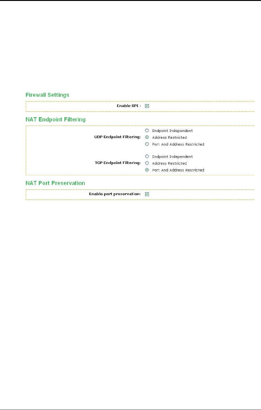
ESR-9710 Wireless N Gigabit Router Version 1.0
58
6.3.10 Firewall
The device provides a tight firewall by virtue of the way NAT works. Unless you
configure the router to the contrary, the NAT does not respond to unsolicited
incoming requests on any port, thereby making your LAN invisible to Internet cyber
attacks. However, some network applications cannot run with a tight firewall. Those
applications need to selectively open ports in the firewall to function correctly. The
options on this page control several ways of opening the firewall to address the
needs of specific types of applications.
Enable SPI: Place a check in this box to enable SPI. SPI ("stateful packet
inspection" also known as "dynamic packet filtering") helps to prevent cyberattacks
by tracking more state per session. It validates that the traffic passing through that
session conforms to the protocol. When the protocol is TCP, SPI checks that packet
sequence numbers are within the valid range for the session, discarding those
packets that do not have valid sequence numbers. Whether SPI is enabled or not,
the router always tracks TCP connection states and ensures that each TCP packet's
flags are valid for the current state.
TCP / UDP NAT Endpoint Filtering options control how the router's NAT manages
incoming connection requests to ports that are already being used. Select one of the
radio buttons.
o End Point Independent Once a LAN-side application has created a
connection through a specific port, the NAT will forward any incoming
connection requests with the same port to the LAN-side application
regardless of their origin. This is the least restrictive option, giving the best
connectivity and allowing some applications (P2P applications in particular)
to behave almost as if they are directly connected to the Internet.
o Address Restricted The NAT forwards incoming connection requests to a
LAN-side host only when they come from the same IP address with which a
connection was established. This allows the remote application to send data
back through a port different from the one used when the outgoing session
was created.
o Port And Address Restricted The NAT does not forward any incoming
connection requests with the same port address as an already establish
connection.
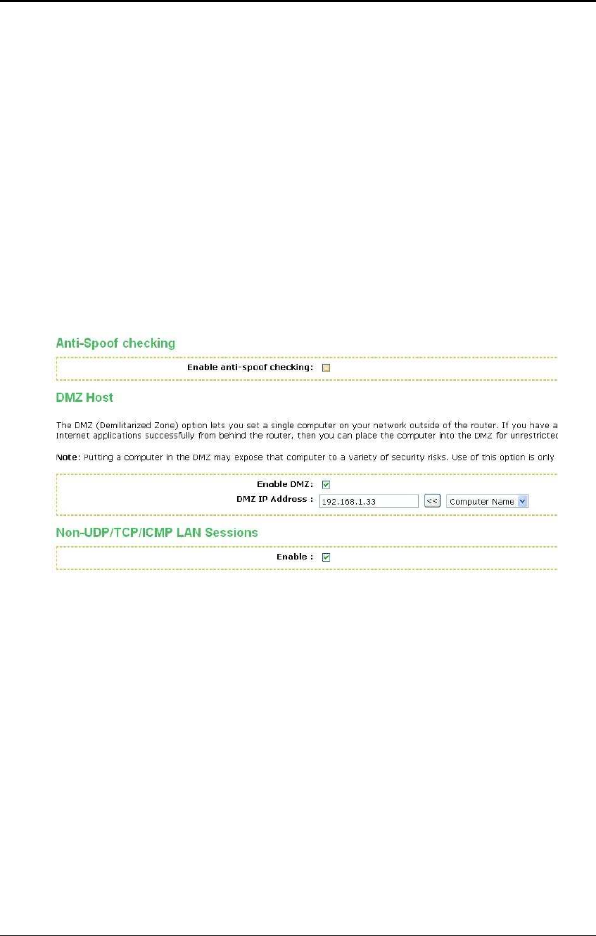
ESR-9710 Wireless N Gigabit Router Version 1.0
59
Note: Some of these options can interact with other port restrictions. Endpoint
Independent Filtering takes priority over inbound filters or schedules, so it is possible
for an incoming session request related to an outgoing session to enter through a
port in spite of an active inbound filter on that port. However, packets will be rejected
as expected when sent to blocked ports (whether blocked by schedule or by inbound
filter) for which there are no active sessions. Port and Address Restricted Filtering
ensures that inbound filters and schedules work precisely, but prevents some level of
connectivity, and therefore might require the use of port triggers, virtual servers, or
port forwarding to open the ports needed by the application. Address Restricted
Filtering gives a compromise position, which avoids problems when communicating
with certain other types of NAT router (symmetric NATs in particular) but leaves
inbound filters and scheduled access working as expected.
Enable Port Preservation: Place a check in this box to enable Port Preservation.
NAT Port preservation (on by default) tries to ensure that, when a LAN host makes
an Internet connection, the same LAN port is also used as the Internet visible port.
This ensures best compatibility for internet communications. Under some
circumstances it may be desirable to turn off this feature.
Enable anti-spoof checking: Place a check in this box to enable anti-spoof
checking. Enabling this option can provide protection from certain kinds of "spoofing"
attacks. However, enble this option with care. With some modems, the WAN
connection may be lost when this option is enabled. In that case, it may be
necessary to change the LAN subnet to something other than 192.168.0.x
(192.168.2.x, for example), to re-establish the WAN connection.
Enable DMZ Host: Place check in this box to enable DMZ host. DMZ host is a
demilitarized zone used to provide Internet services without sacrificing unauthorized
access to its local private network. Typically, the DMZ host contains devices
accessible to Internet traffic, such as web, FTP, email and DNS servers.
DMZ IP Address: Specify the IP address of the DMZ host.
Non-UDP/TCP/ICMP LAN Sessions: Place a check in this box to enable this feature.
When a LAN application that uses a protocol other than UDP, TCP, or ICMP initiates
a session to the Internet, the router's NAT can track such a session, even though it
does not recognize the protocol. This feature is useful because it enables certain
applications (most importantly a single VPN connection to a remote host) without the
need for an ALG.
Note: This feature does not apply to the DMZ host (if one is enabled). The DMZ host
always handles these kinds of sessions.
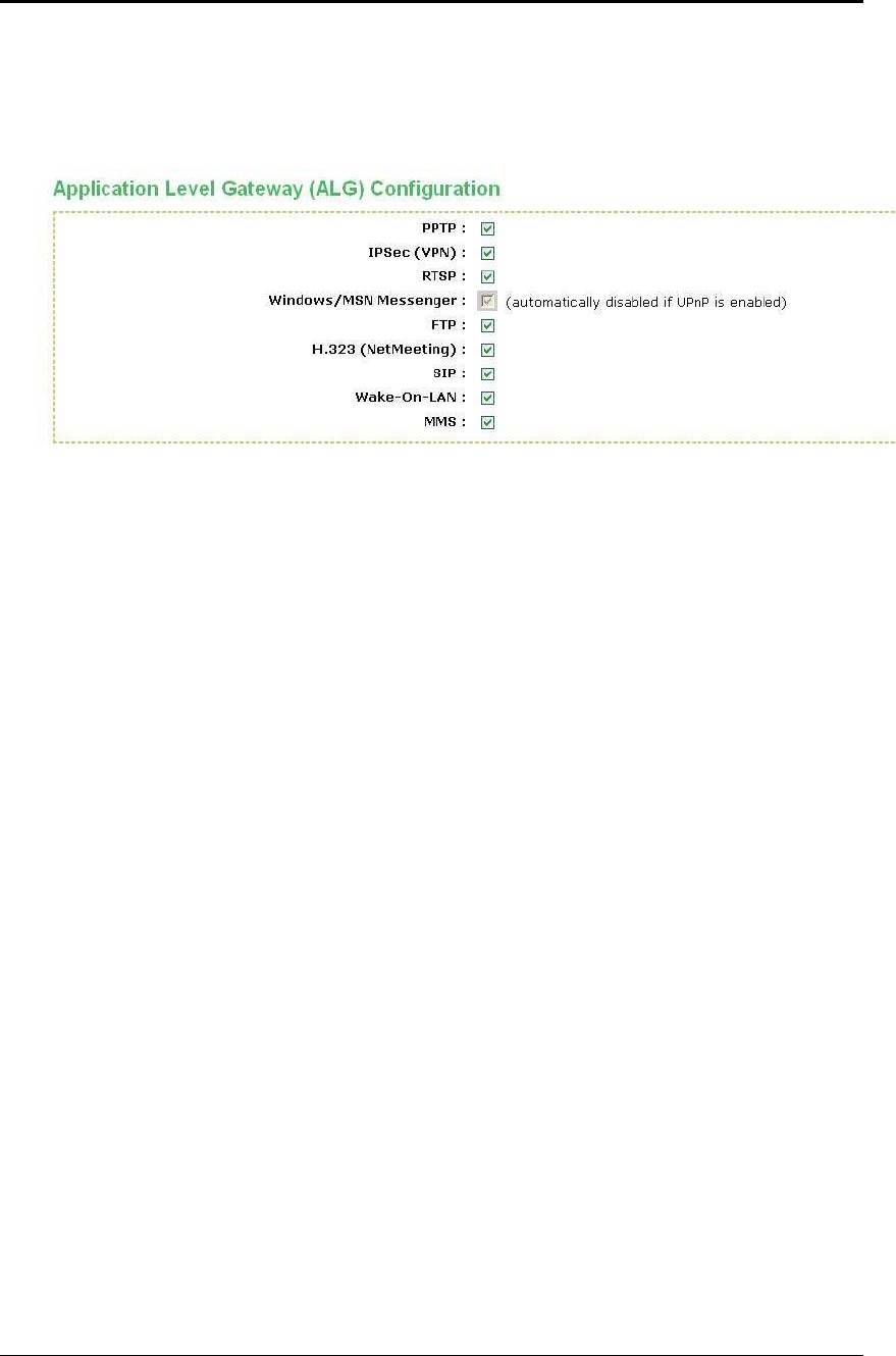
ESR-9710 Wireless N Gigabit Router Version 1.0
60
Enabling this option (the default setting) enables single VPN connections to a remote
host. (But, for multiple VPN connections, the appropriate VPN ALG must be used.)
Disabling this option, however, only disables VPN if the appropriate VPN ALG is also
disabled.
Application Layer Gateway (ALG) Configuration: Place a check in appropriate
feature boxes to enable them. . Some protocols and applications require special
handling of the IP payload to make them work with network address translation
(NAT). Each ALG provides special handling for a specific protocol or application. A
number of ALGs for common applications are enabled by default.
o PPTP: Allows multiple machines on the LAN to connect to their corporate
networks using PPTP protocol. When the PPTP ALG is enabled, LAN
computers can establish PPTP VPN connections either with the same or with
different VPN servers. When the PPTP ALG is disabled, the router allows
VPN operation in a restricted way -- LAN computers are typically able to
establish VPN tunnels to different VPN Internet servers but not to the same
server. The advantage of disabling the PPTP ALG is to increase VPN
performance. Enabling the PPTP ALG also allows incoming VPN
connections to a LAN side VPN server (refer to Advanced → Virtual Server).
o IPSec: (VPN) Allows multiple VPN clients to connect to their corporate
networks using IPSec. Some VPN clients support traversal of IPSec through
NAT. This option may interfere with the operation of such VPN clients. If you
are having trouble connecting with your corporate network, try disabling this
option. Check with the system adminstrator of your corporate network
whether your VPN client supports NAT traversal.
o RTSP: Allows applications that use Real Time Streaming Protocol to receive
streaming media from the internet. QuickTime and Real Player are some of
the common applications using this protocol.
o Windows/MSN Messenger: Supports use on LAN computers of Microsoft
Windows Messenger (the Internet messaging client that ships with Microsoft
Windows) and MSN Messenger. The SIP ALG must also be enabled when
the Windows Messenger ALG is enabled.
o FTP: Allows FTP clients and servers to transfer data across NAT.
o H.323 (Netmeeting): Allows H.323 (specifically Microsoft Netmeeting) clients
to communicate across NAT server.
o SIP: Allows devices and applications using VoIP (Voice over IP) to
communicate across NAT. Some VoIP applications and devices have the
ability to discover NAT devices and work around them. This ALG may
interfere with the operation of such devices. If you are having trouble making
VoIP calls, try turning this ALG off.