Senao Networks TR9360 Wireless-N Pocket AP/Router User Manual Part 1
Senao Networks, Inc. Wireless-N Pocket AP/Router Part 1
UserManual.wiki
>
Senao Networks
>
TR9360 User Manual
>
User Manual Part 1
Contents
1.
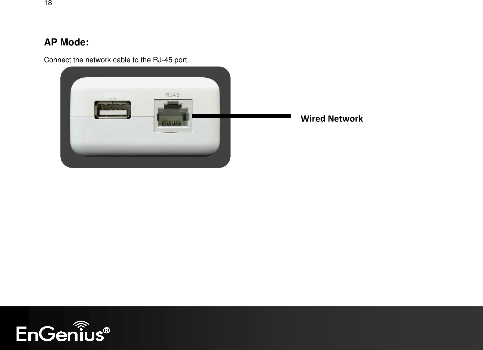
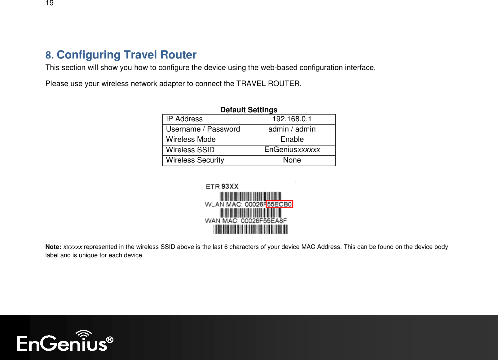
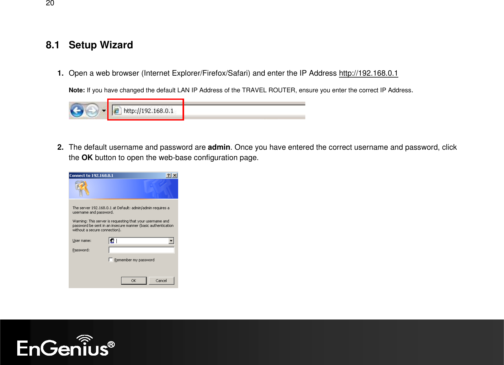
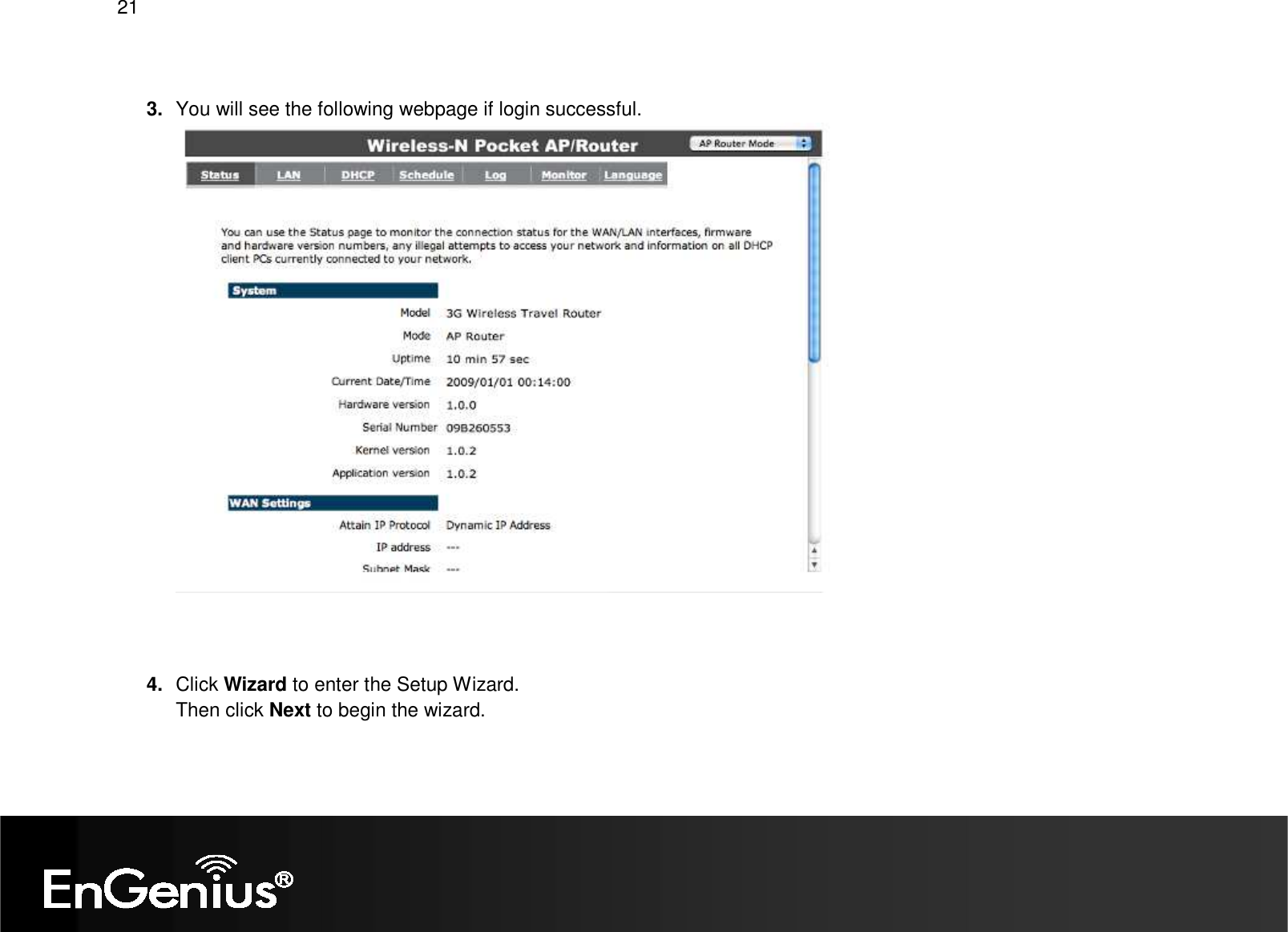
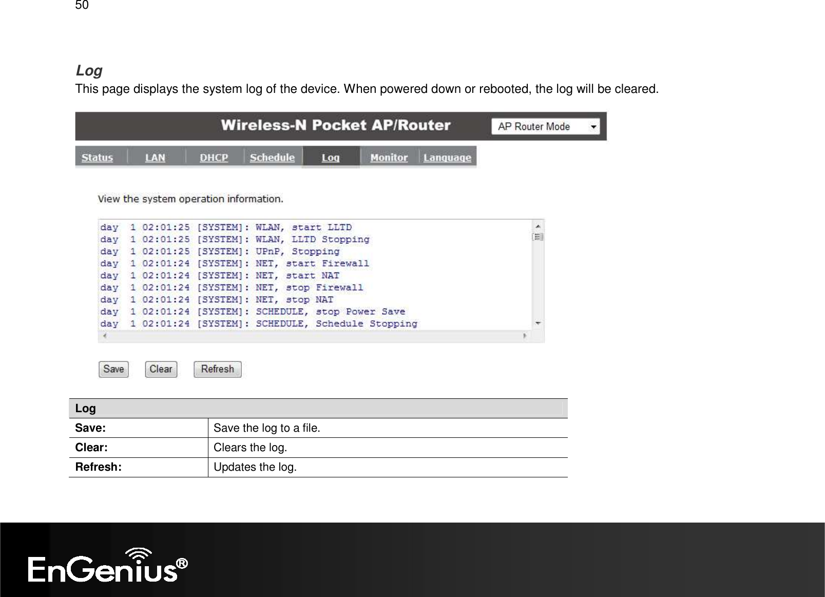
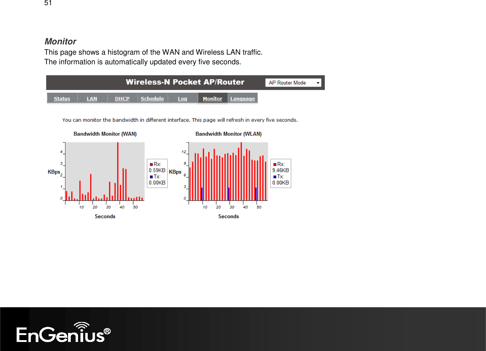
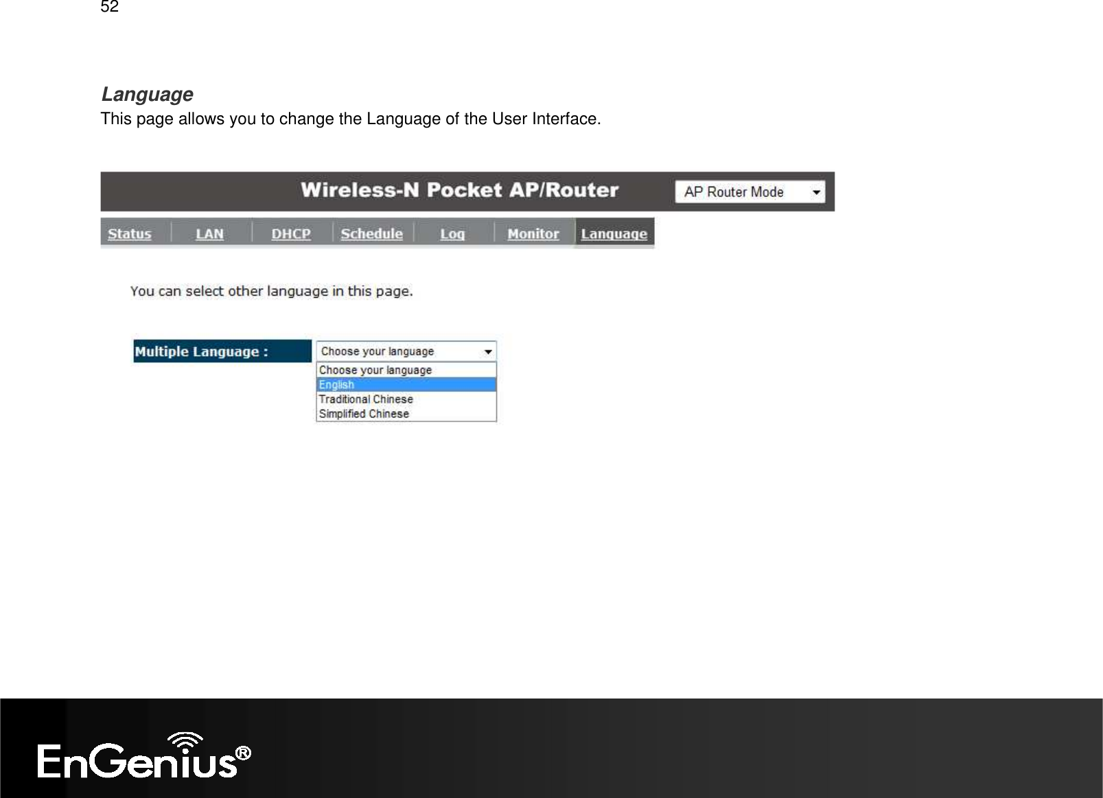
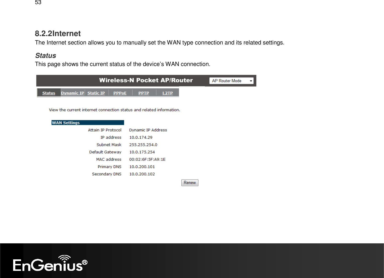
User Manual Part 1
2.
User Manual Part 2
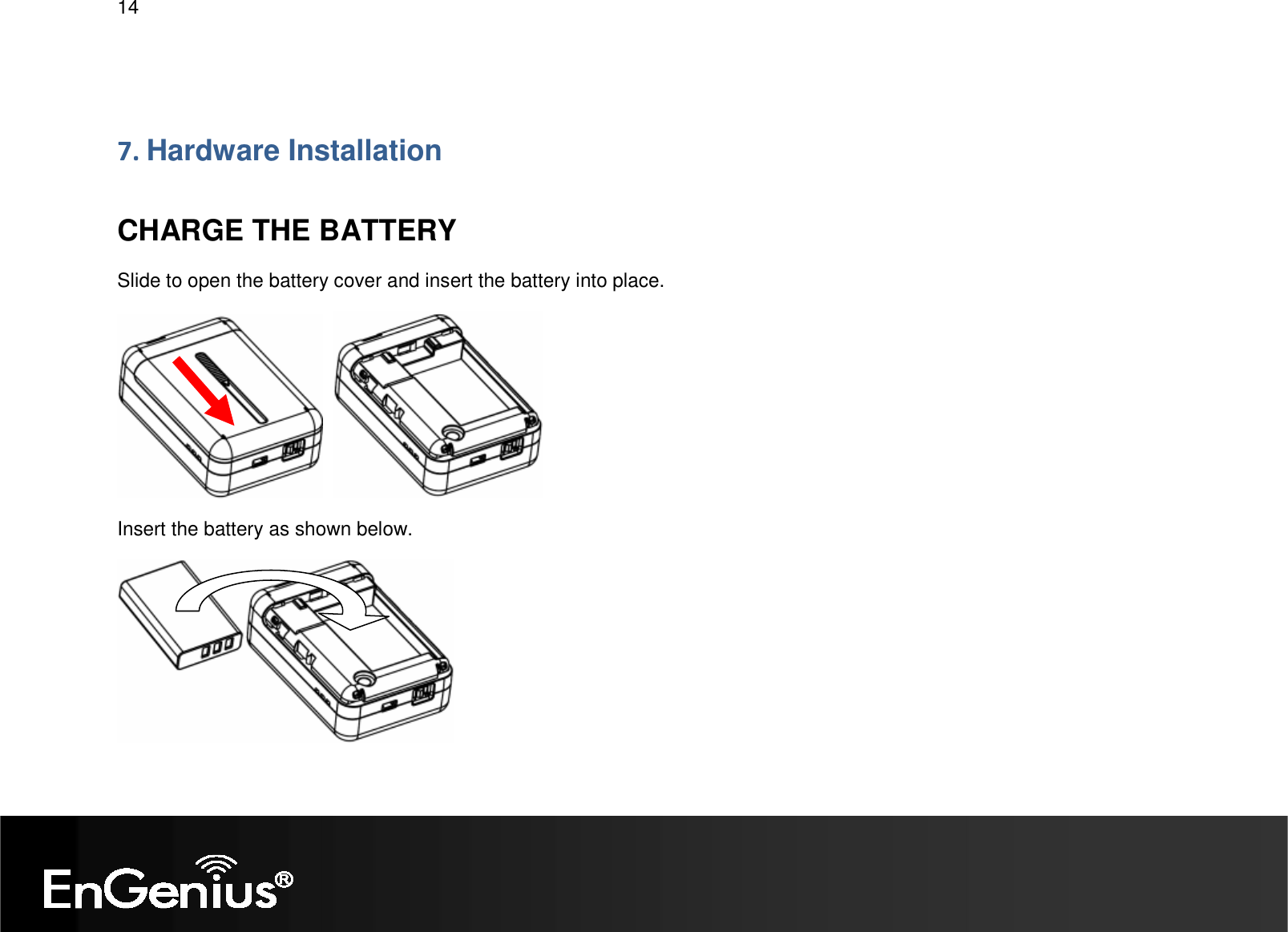
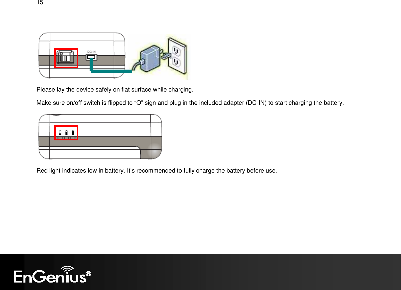
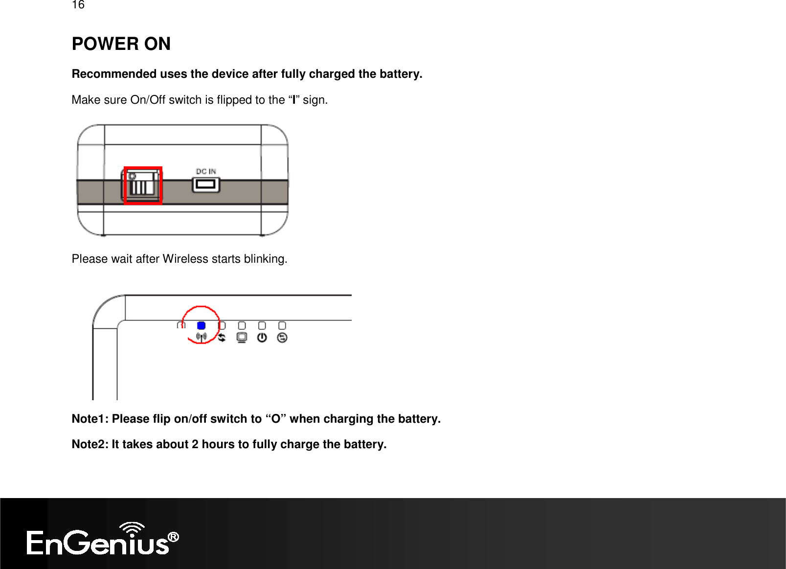
User Manual Part 1
Navigation menu
Upload a User Manual
Namespaces
Wiki Guide
HTML
PDF
Info
Views
User Manual
Discussion / Help
Navigation
![12 3. Right click on [Local Area Connection] and select [Properties]. Windows Vista, click [View Network Status and Tasks] then [Manage Network Connections] 2. Windows XP, click [Network Connection]](https://usermanual.wiki/Senao-Networks/TR9360.User-Manual-Part-1/User-Guide-1344610-Page-13.png)
![13 4. Check “Client for Microsoft Networks”, “File and Printer Sharing”, and “Internet Protocol (TCP/IP) is ticked. If not, please install them. 6. Select “Obtain an IP Address automatically” and “Obtain DNS server address automatically” then click [OK]. 5. Select “Internet Protocol (TCP/IP)” and click [Properties]](https://usermanual.wiki/Senao-Networks/TR9360.User-Manual-Part-1/User-Guide-1344610-Page-14.png)