Senao Networks WAP7301AG 802.11 abgn∾ device User Manual WAP7301AG installation guide v01
Senao Networks, Inc. 802.11 abgn∾ device WAP7301AG installation guide v01
Users Manual.pdf

WAP7301AG
Installation Guide
Indoor Enterprise AP
V. 0.1
PRODUCT DESCRIPTION
!"#$%&'"()*+),)-.,//)0/,123)*45667)898):;<;=>)?@A?B?C)D&8E'',F),FF2++)06*41E))B1)+G00671+)
5G,/)H,45)5G,/)7,5*6),45)076I*52+)J*KJ)027L67M,4F2).*L*),FF2++)16)1J2)524+2)24I*764M241)
,00/*F,1*64E)
!"#$%&'"()2NG*0025).*1J)1J722)(*K,H*1)O1J27421)P"Q)F6442F1*64+),45)642)6L)1J2)O1J27421)0671)
*+)#6O)R6G7F2):#RO>).J*FJ)F,4)06.27)64),)72M612)#6.2725);2I*F2):#;>).*1J)D&8E%,L)06.27)HG5K21E)
')0,++*I2)0,++A1J76GKJ)0671S)*1).6431)H/6FT)1J2)67*K*4,/)F6442F1*64)L76M)1J2).,//)U,FTE) ) )
!"#$%&'"()6027,12+)L76M)+1,45,75)D&8E%,L)67),1)06.27A6I27AO1J27421):#6O>)+6G7F2+E) ) !J24)
6027,12)G4527)1J2),1)06.27)HG5K21S)+V+12M)F,4)076I*52)1J2)'&!)6G1)L76M)1J2)#RO)0671W)67)
!"#$%&'"().*1J6G1),4V)#;)F6442F1*64)F,4)6027,12)G4527)1J2),L)06.27)HG5K21E)
▌PACKAGE CONTENT
! WAP7301AG Access Point
! WAP7301AG Quick Start Guidet
! Mounting Bracket
! Mounnting screw kits (includes washers, wall anchors and bolts)
▌CONNECT TO THE WAP7301AG ACCESS POINT
1. Power is provided through one Ethernet ports (WAN port). This is the preferred method of
powering the AP on wall installations.
2. The WAP7301AG can also be powered by an external DC power supply plugged into an
AC source. Plug the supply’s input jack into the DC-In port

▌MOUNTING OF THE WAP7301AG ACCESS POINT
WALL MOUNT/JUNCTION OR GANG BOX MOUNT
1. Wall: Using the mounting bracket (Figure 1) as a mapping kit to wall.
Choose a location that allow the LAN cables to come out of the wall within the
rectagular hole on bracket. Place the bracket against the wall. Decide two
holes to use in order to mount the bracket. The two holes should be on
opposite sides in order to hold off to the wall.
Junction/Gang Box: Place the bracket over the junction box with the
captive screw on the left side and the flat plate against the wall. The bracket
should be attached to a vetical surface. Align two of the bracket holes with two
of the box’s holes. Using the two pan head machine screw, attached the
bracket to the box using the aligned sholes.
2. Mark the two hole centers. And screw in the provided plastic anchors into the
holes.
3. Attach the bracket using the provided two screws.
4. Connect the LAN Cable from the wall and attached the AP to the mounting
bracket. The captive screw will be used to lock the AP in place.
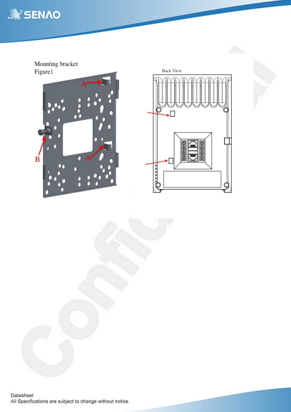
A of the bracket goes to holes on the back of the AP.
B (Captive screw) matches the locking mechanism on the side of the AP.

Federal Communication Commission Interference Statement
This equipment has been tested and found to comply with the limits for a Class B digital device, pursuant to
Part 15 of the FCC Rules. These limits are designed to provide reasonable protection against harmful
interference in a residential installation. This equipment generates, uses and can radiate radio frequency
energy and, if not installed and used in accordance with the instructions, may cause harmful interference to
radio communications. However, there is no guarantee that interference will not occur in a particular
installation. If this equipment does cause harmful interference to radio or television reception, which can
be determined by turning the equipment off and on, the user is encouraged to try to correct the interference
by one of the following measures:
- Reorient or relocate the receiving antenna.
- Increase the separation between the equipment and receiver.
- Connect the equipment into an outlet on a circuit different from that
to which the receiver is connected.
- Consult the dealer or an experienced radio/TV technician for help.
FCC Caution: Any changes or modifications not expressly approved by the party responsible for compliance
could void the user's authority to operate this equipment.
This device complies with Part 15 of the FCC Rules. Operation is subject to the following two conditions: (1)
This device may not cause harmful interference, and (2) this device must accept any interference received,
including interference that may cause undesired operation.
This transmitter must not be co-located or operating in conjunction with any other antenna or transmitter.
Operations in the 5.15-5.25GHz band are restricted to indoor usage only.
IMPORTANT NOTE:
FCC Radiation Exposure Statement:
This equipment complies with FCC radiation exposure limits set forth for an uncontrolled environment. This
equipment should be installed and operated with minimum distance 20cm between the radiator & your body.