Senao Networks WBR2100AFN Wireless 11b/g/n Router User Manual WBR2100AFN UM
Senao Networks, Inc. Wireless 11b/g/n Router WBR2100AFN UM
Contents
- 1. User Manual - Statements
- 2. User Manual (CR3000)
- 3. User Manual (WBR2100AFN)
User Manual (WBR2100AFN)

1
WBR2100AFN
Wireless 11b/g/n Router
(802.11n, 802.11g & 802.11b)
User Manual
Version: 1.0

2
T
ABLE OF
C
ONTENTS
1
INTRODUCTION ........................................................................................................................4
2
KEY FEATURES..........................................................................................................................5
3
PACKAGE CONTENTS..............................................................................................................6
4
PRODUCT LAYOUT...................................................................................................................7
5
NETWORK + SYSTEM REQUIREMENTS.............................................................................9
6
WBR2100AFN PLACEMENT ....................................................................................................9
7
SETUP LAN, WAN.....................................................................................................................10
8
PC NETWORK ADAPTER SETUP (WINDOWS XP) ............................................................11
9
BRING UP WBR2100AFN.........................................................................................................13
10
SMART WIZARD ......................................................................................................................13
11
INITIAL SETUP WBR2100AFN...............................................................................................21
12 AP ROUTER MODE......................................................................................................................23
13 REPEATER MODE.......................................................................................................................76
APPENDIX A – FCC INTERFERENCE STATEMENT..................................................................92
APPENDIX B – IC INTERFERENCE STATEMENT .....................................................................93
APPENDIX C – CE INTERFERENCE STATEMENT....................................................................94

3
Revision History
Version Date Notes
1.0 November 18, 2008 Modified from existing UM.

4
1 Introduction
Congratulations on your purchase of WBR2100AFN Wireless Network
Broadband Router. WBR2100AFN is compliant with draft 802.11n v2.0 up to 6
times faster than standard 802.11g based routers while still being compatible
with 802.11g & 802.11b gadgets. WBR2100AFN is not only a Wireless Access
Point, but also doubles as a 4-port full-duplex Switch that connects your wired-
Ethernet devices together at incredible speeds.
At 300 Mbps wireless transmission rate, Access Point built into the Router
uses advanced MIMO (Multi-Input, Multi-Output) technology to transmit multiple
steams of data in a single wireless channel giving you seamless access to
multimedia content. Robust RF signal travels farther, eliminates dead spots and
extends network range. For data protection and privacy, WBR2100AFN encodes
all wireless transmissions with WEP, WPA, and WPA2 encryption.
With inbuilt DHCP Server & powerful SPI firewall WBR2100AFN protects your
computers against intruders and most known Internet attacks but provides safe
VPN pass-through. With incredible speed and QoS function of 802.11n, (draft2.0)
WBR2100AFN is ideal for media-centric applications like streaming video,
gaming, and VoIP telephony to run multiple media-intense data streams through
the network at the same time, with no degradation in performance.

5
2 Key Features
Features Advantages
Incredible Data Rate up to 300Mbps**
Heavy data payloads such as
MPEG video streaming
IEEE 802.11n Compliant and
backward compatible with 802.11b/g
Fully Interoperable with IEEE
802.11b / IEEE 802.11g compliant
devices with legacy protection
Four 10/100 Mbps Fast Switch Ports
(Auto-Crossover)
Scalability, extend your network.
Firewall supports, DMZ, MAC Filter, IP
Filter, URL Filter, ICMP Blocking, SPI,
Port Mapping, Port Forwarding, Port
Trigger
Avoids the attacks of Hackers or
Viruses from Internet
Support 802.1x Authenticator, 802.11i
(WPA/WPA2, AES), VPN pass-through
Provide mutual authentication
(Client and dynamic encryption
keys to enhance security
WDS (Wireless Distribution System) Make wireless AP and Bridge mode
simultaneously as a wireless
repeater
** Theoretical wireless signal rate based on IEEE standard of 802.11a, b, g, n chipset used. Actual
throughput may vary. Network conditions and environmental factors lower actual throughput rate.
All specifications are subject to change without notice.

6
3 Package Contents
Open the package carefully, and make sure that none of the items listed below
are missing. Do not discard the packing materials, in case of return; the unit must
be shipped back in its original package.
1. 802.11n SOHO Router
2. 100V~240V Power Adapter
3. 2dBi 2.4GHz SMA Upgradable Antennas x 2 pcs
4. Quick Install Guide
5. CD (User’s Manual)
6. Warranty card

7
4 Product Layout
LED Description
POWER
Lights up when powered ON. Blinks on
TEST/RESET
WLAN
Lights up in ORANGE when WLAN is
enabled. Blinks on traffic
LAN PORT ACTIVY
Blinks on traffic for specific LAN PORT

8
100 Mbps Lights up when 100 Mbps data rate
enabled on that specific port
ITEM Description
Reset
Click this button to restart the system, or
Press this button and hold for 10 seconds
to restart the system.
WPS
Click this button to start WPS function.
DC IN
Power connector, connects to DC 12V
Power Adapter
LAN1 ~ 4
Local Area Network (LAN) ports 1 to 4
INTERNET
Wide Area Network(WAN) port

9
5 Network + System Requirements
To begin using the WBR2100AFN, make sure you meet the following as
minimum requirements:
PC/Notebook.
Operating System – Microsoft Windows 98SE/ME/XP/2000/VISTA
1 Free Ethernet port.
WiFi card/USB dongle (802.11b/g/n) – optional.
External xDSL (ADSL) or Cable modem with an Ethernet port (RJ-45).
PC with a Web-Browser (Internet Explorer, Safari, Firefox, Opera etc.)
Few Ethernet compatible CAT5 cables.
6 WBR2100AFN Placement
You can place WBR2100AFN on a desk or other flat surface, or you can mount it
on a wall. For optimal performance, place your Wireless Broadband Router in the
center of your office (or your home) in a location that is away from any potential
source of interference, such as a metal wall or microwave oven. This location
must be close to a power connection and your ADSL/Cable modem. If the
antennas are not positioned correctly, performance loss can occur.

10
7 Setup LAN, WAN
LAN connection:
Connect Ethernet cable between your PC/Notebook LAN port
& one of the 4 available LAN ports on WBR2100AFN.
WAN connection:
Connect Ethernet cable between WAN ports of your
ADSL/CABLE modem & INTERNET port of WBR2100AFN.
Make sure your ADSL/CABLE modem is working well. Contact
your ISP if you have any questions.
11
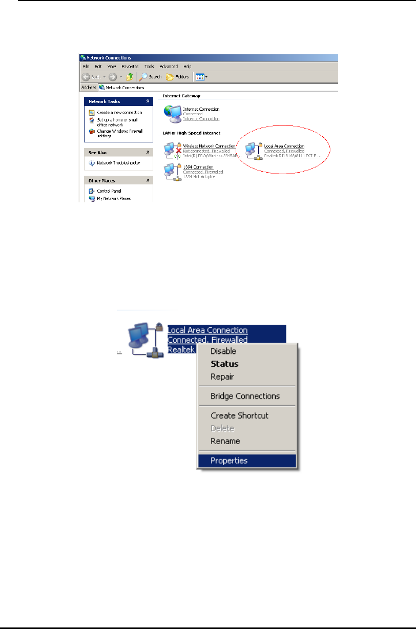
8 PC Network Adapter setup (
Windows XP
)
• Enter [Start Menu] select [Control panel] select [Network].
• Select [Local Area Connection]) icon=>select [properties]
12
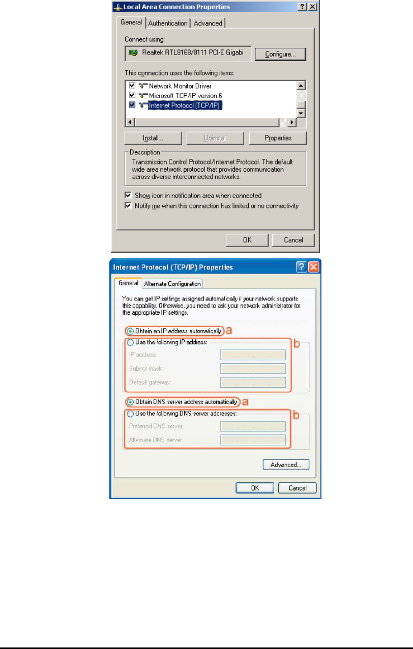
• Select [Internet Protocol (TCP/IP)] =>Click [Properties].
• Select the [General] tab.
a. WBR2100AFN supports [DHCP] function, please select both [Obtain an IP
address automatically] and [Obtain DNS server address automatically].

13
9 Bring up WBR2100AFN
Connect the supplied power-adapter to the power inlet port and connect it to a
wall outlet. Then, WBR2100AFN automatically enters the self-test phase. During
self-test phase, Power LED will blink briefly, and then will be lit continuously to
indicate that this product is in normal operation.
10 Smart Wizard
CHECK
• Internet connection should be setup & ready to use (ADSL or cable modem).
• Modem must provide RJ45 port to connect with WBR2100AFN.
• Microsoft Windows compatible PC/Notebook with UPnP enabled network
adapter
• CAT 5 network cable(s), RJ45 port on PC/Notebook.
STEP 1
Connect WBR2100AFN WAN port & your modem WAN port with RJ45 cable.
STEP 2
Power up WBR2100AFN.POWER led on front panel lights up & remains
stable.
STEP 3
Connect WBR2100AFN LAN port & PC/Notebook RJ45 port with network
cable.
14
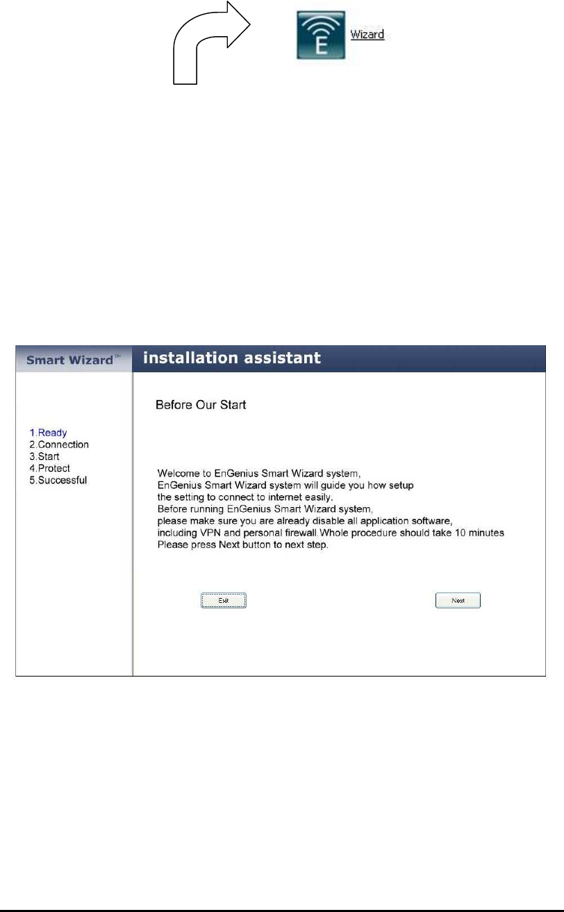
Click on this icon to run SMART WIZARD.
Click Setup Wizard to setup your WBR2100AFN router.
Click User Manual to launch smart wizard user manual.
Click Adobe Reader to setup Adobe Acrobat reader on your PC/Notebook.
Click EXIT anytime you want to abort.
Click <Next> to proceed. Click <Exit> to abort.
15
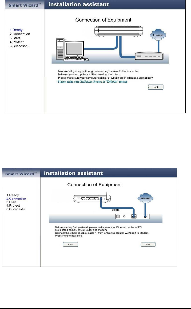
WBR2100AFN should be setup as depicted above.
Make sure your DSL/CABLE modem is setup and working. Else take the help
of your internet service provider.
Click <Next> to proceed.
16
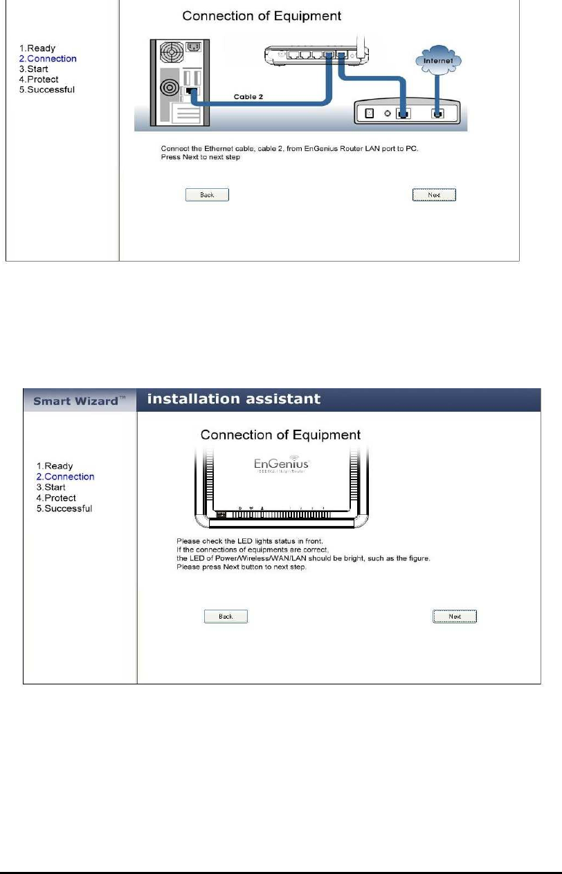
Check the MODEM and WBR2100AFN connection. It should be as shown below.
Check power connection for modem as well as WBR2100AFN.
Make sure antenna is connected to rear panel of WBR2100AFN.
Click <Next> to proceed.
Notice the LED that should be light up at this stage. If not, check your
procedures again.
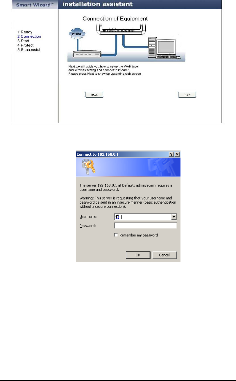
Click <Next> to configure WAN & Wireless settings.
17
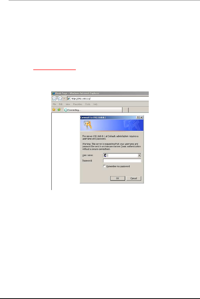
User name and password are admin/admin. Click <OK>. Your default
browser will connect to WBR2100AFN Web Server http://192.168.0.1 .
18
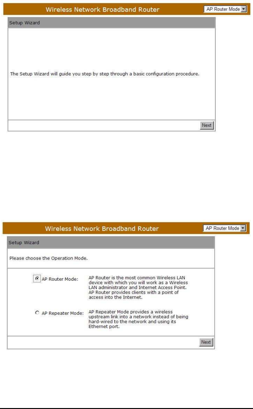
Click <Next> to enter mode selection.
Select the mode that WBR2100AFN is going to be and set its configurations. AP
Repeater mode does not enable WAN interface, Setup Wizard will skip WAN
Configuration.
Click <Next> to automatically detect your Internet Network settings.
19
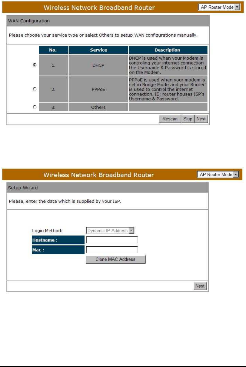
You could choose your service type or select Others to setup WAN
configurations manually.
Smart Wizard has detected DHCP client. Configure the host name and MAC
address of your ADSL modem. Click Next to proceed.
Smart Wizard has finished setting up WAN Configuration. Click <Next> to
proceed.
20
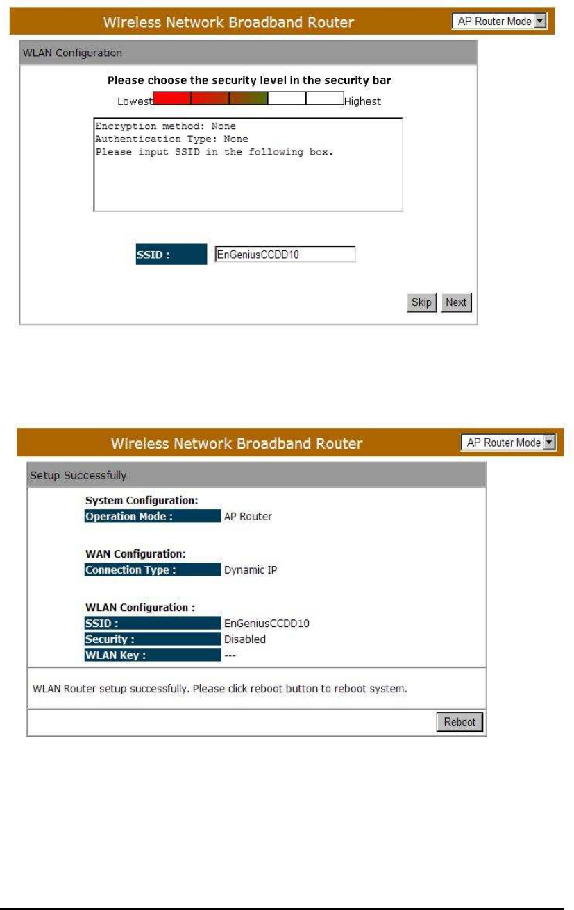
Enter the name for your wireless network (SSID) and security key
Click <Next> to proceed
To apply the entire configuration, click <Reboot>.
NOTE: After Wireless settings are applied, you need to connect from your
WLAN client with the security settings you just finished configuring.
Remember the type of security & security key.
21
11 Initial Setup WBR2100AFN
WBR2100AFN uses web-interface for configuration to be accessed through
your web browser, such as Internet Explorer or Netscape Communicator.
- LOGIN Procedure
1. OPEN your browser (e.g. Internet Explorer).
2. Type http://192.168.0.1 in address bar and hit [Enter] button on your
keyboard.
22
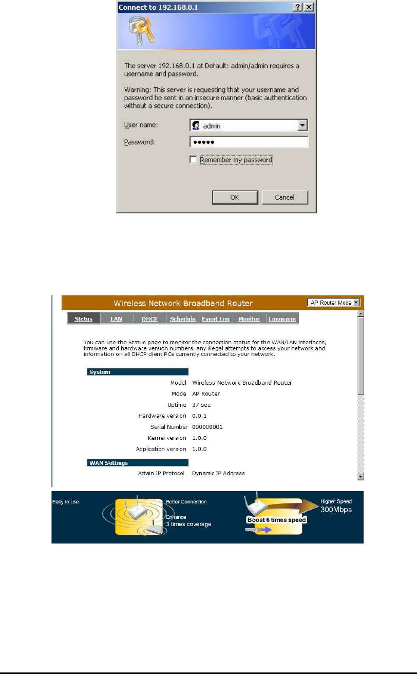
3. Click <OK> to navigate into WBR2100AFN configuration home page.
4. You will see the home page of WBR2100AFN as follows.
23
12 AP Router Mode
System
- Status
This page allows you to monitor the current status of your router. You can use the
status page to quickly see if you have any updated firmware available (bug fixes,
updates). You can navigate from this page with a few interesting options for
reminding or skipping this page forever & so forth.
Once you click on <OK> button to go to the requested page, you can see the
status page of the WBR2100AFN.
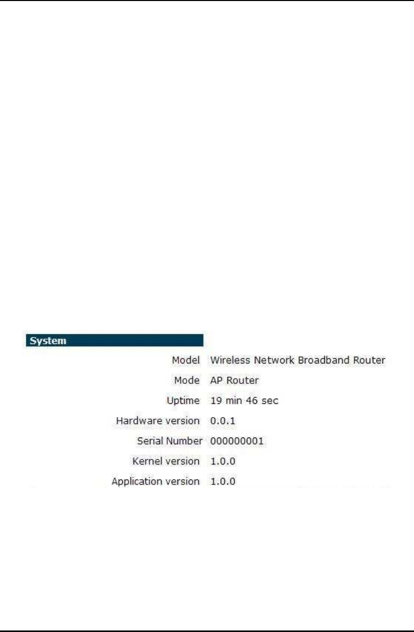
System: You can see the UP time, hardware information, serial number as well
as firmware version information.
24
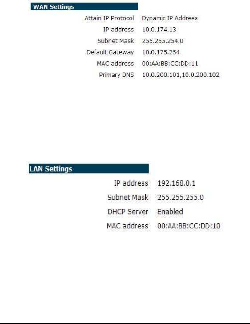
WAN Settings: This section displays whether the WAN port is connected to a
Cable/DSL connection. It also displays the router’s WAN IP
address, Subnet Mask, and ISP Gateway as well as MAC
address, the Primary DNS.
LAN Settings: This section displays the Broadband router LAN port’s current
LAN & WLAN information. It also shows whether the DHCP
Server function is enabled / disabled.
25
WLAN Settings: This section displays the current WLAN configuration settings
you’ve configured in the Wizard / Basic Settings / Wireless
Settings section. Wireless configuration details such as SSID,
Security settings, BSSID, Channel number, mode of
operation are briefly shown.
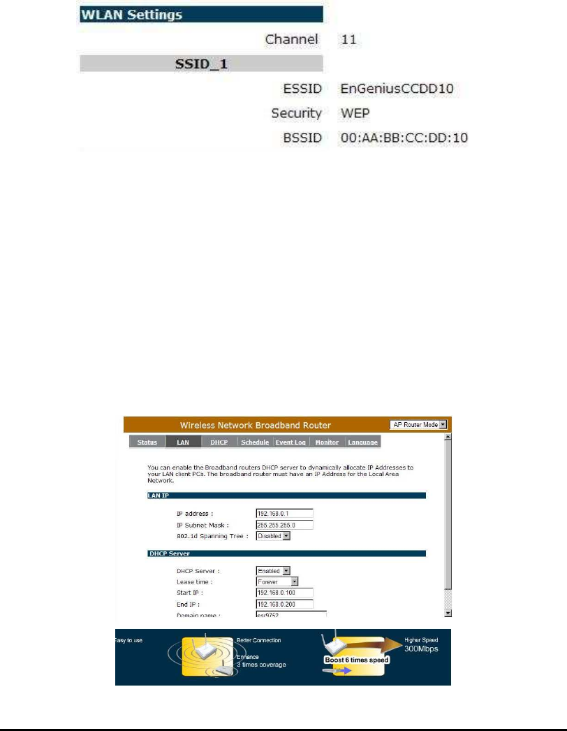
- LAN
The LAN Tabs reveals LAN settings which can be altered at will. If you are an
entry level user, try accessing a website from your browser. If you can access
website without a glitch, just do not change any of these settings.
Click <Apply> at the bottom of this screen to save the changed configurations.

26
LAN IP
IP address: 192.168.0.1. It is the router’s LAN IP address (Your LAN clients
default gateway IP address). It can be changed based on your own
choice.
IP Subnet Mask: 255.255.255.0 Specify a Subnet Mask for your LAN segment.
802.1d Spanning Tree: This is disabled by default. If 802.1d Spanning Tree
function is enabled, this router will use the spanning
tree protocol to prevent network loops.
DHCP Server
DHCP Server: This will enable or disable the Dynamic Pool setting..
Lease time: This is the lease time of each assigned IP address.
Start IP: This will be the beginning of the pool of IP addresses available for client
devices.
End IP: This will be the end of the pool of IP addresses available for client devices.
Domain name: The Domain Name for the existing or customized network.
27
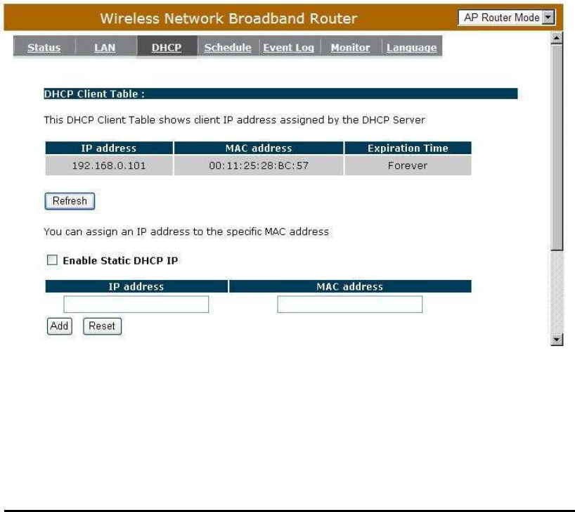
- DHCP
View the current LAN clients which are assigned with an IP Address by the
DHCP-server.
This page shows all DHCP clients (LAN PCs) currently connected to
your network. The table shows the assigned IP address, MAC address and
expiration time for each DHCP leased client. Use the <Refresh> button to update
the available information. Hit <Refresh> to get the updated table.
You can check “Enable Static DHCP IP“. It is possible to add more static
DHCP IPs. They are listed in the table “Current Static DHCP Table“. IP address
can be deleted at will from the table.
Click <Apply> button to save the changed configuration.
28
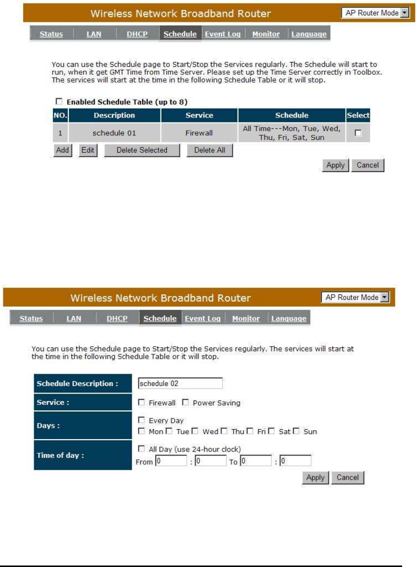
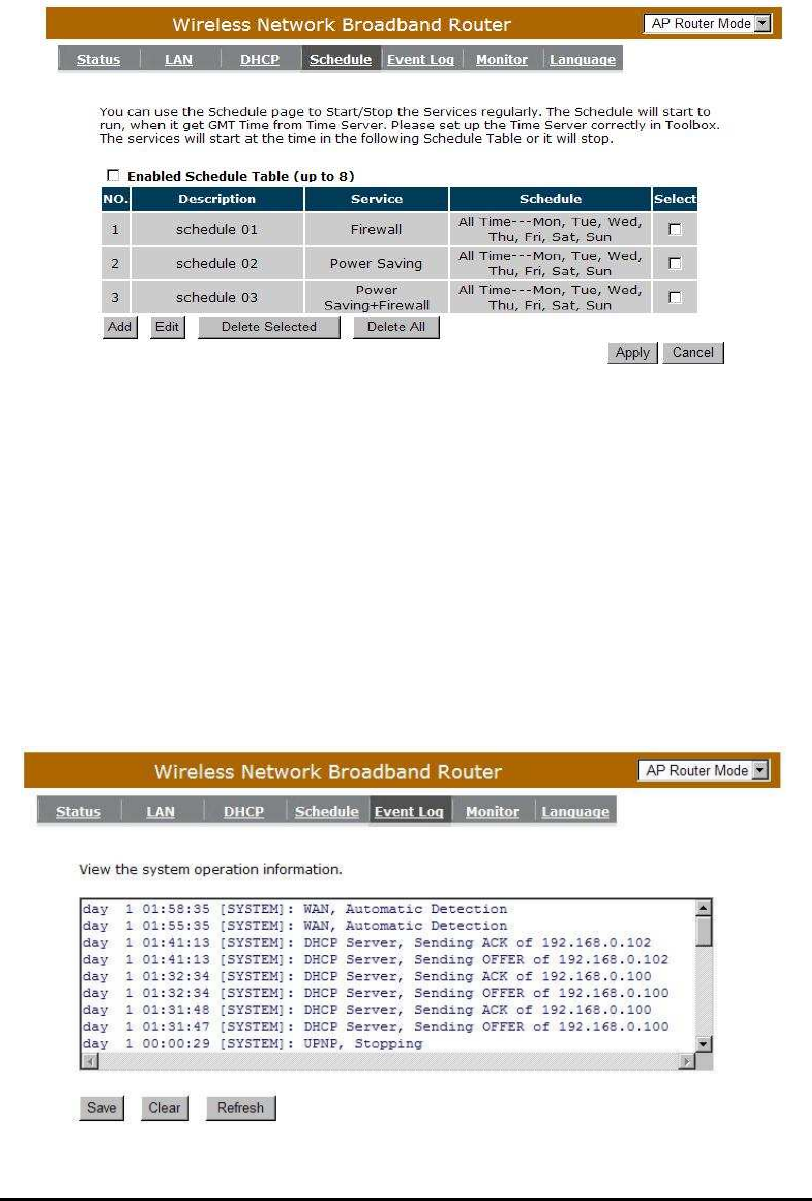
- Schedule
This page allows user to set up schedule function for Firewall and Power Saving
.
Add schedule, edit schedule options to allow configuration of firewall and power
savings services. Fill in the schedule and select type of service. Click <Apply> to
implement those settings.
29
The schedule table lists the pre-schedule service-runs. You can select any of
them using the check box.
- Event Log
View operation event log. This page shows the current system log of the
Broadband router. It displays any event occurred after system start up. At the
bottom of the page, the system log can be saved <Save> to a local file for further
processing or the system log can be cleared <Clear> or it can be refreshed
<Refresh> to get the most updated information. When the system is powered
down, the system log will disappear if not saved to a local file.
30
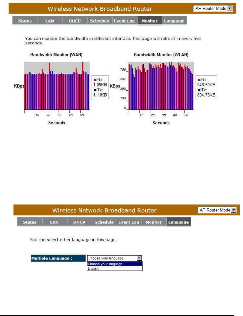
- Monitor
Show histogram for network connection on WAN, LAN & WLAN. Auto refresh
keeps information updated frequently.
- Language
This Wireless Router support multiple language of web pages, You could
select your native language here.
31
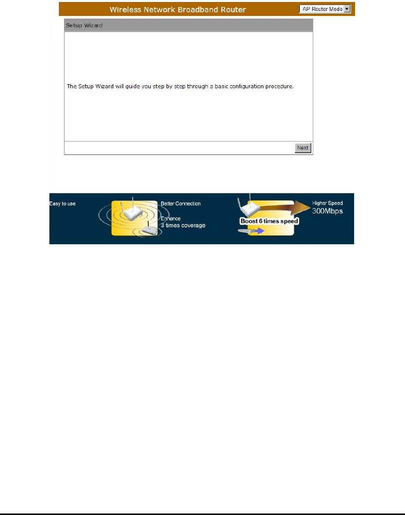
Wizard
Click Wizard to configure the Broadband Router. Setup wizard will now be
displayed; check that the modem is connected and click <Next>. The details
please refer to Smart Wizard <Page 13>.
32
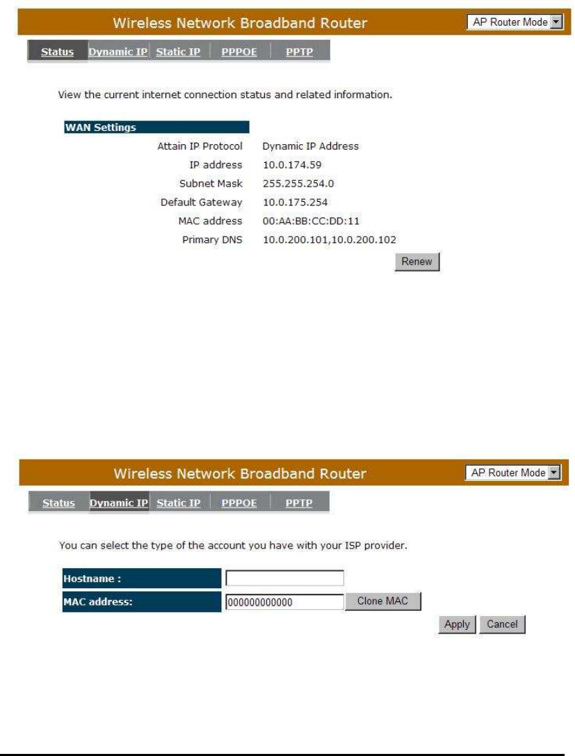
INTERNET
- Status
This page shows the current Internet connection type and status
- Dynamic IP
Use the MAC address when registering for Internet service, and do not change it
unless required by your ISP. If your ISP used the MAC address of the Ethernet
card as an identifier, connect only the PC with the registered MAC address to the
broadband router and click the <Clone MAC Address> button. This will replace
the current MAC address with the already registered Ethernet card MAC address
Host Name: This is optional.
MAC address: The default value is set to the WAN’s physical interface of the
broadband router.
33
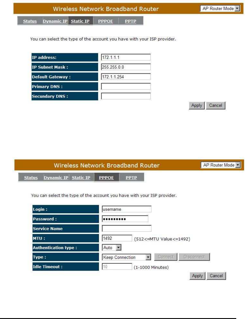
- Static IP
If your ISP Provider has assigned a fixed IP address, enter the assigned IP
address, Subnet mask, Default Gateway IP address, and Primary DNS of your ISP
provider.
- Point-to-Point over Ethernet Protocol (PPPoE)
34
Login / Password: Enter the PPPoE username and password assigned by your
ISP Provider.
Service Name: This is normally optional.
Maximum Transmission Unit (MTU): This is the maximum size of the packets.
Type: Enable the Auto-reconnect option to automatically re-establish the
connection when an application attempts to access the Internet again.
Idle Timeout: This is a maximum period of time for which the Internet
connection is maintained during inactivity. If the connection is inactive for
longer than the Maximum Idle Time, it will be dropped.
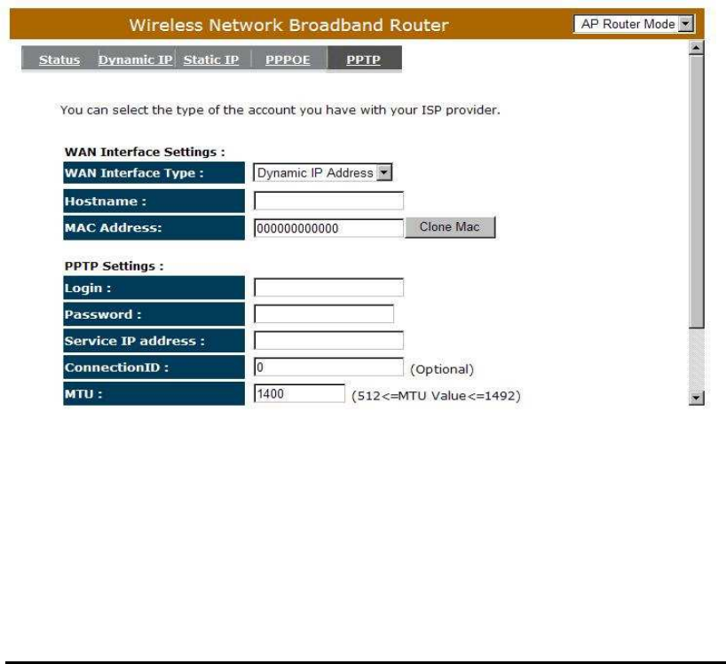
- Point-to-Point Tunneling Protocol (PPTP)
PPTP allows the secure connection over the Internet by simply dialing in a local
point provided by your ISP provider. The following screen allows client PCs to
establish a normal PPTP session and provides hassle-free configuration of the
PPTP client on each client PC.
Click <Apply> to save configuration and connect to ISP provider.
35
Wireless Settings
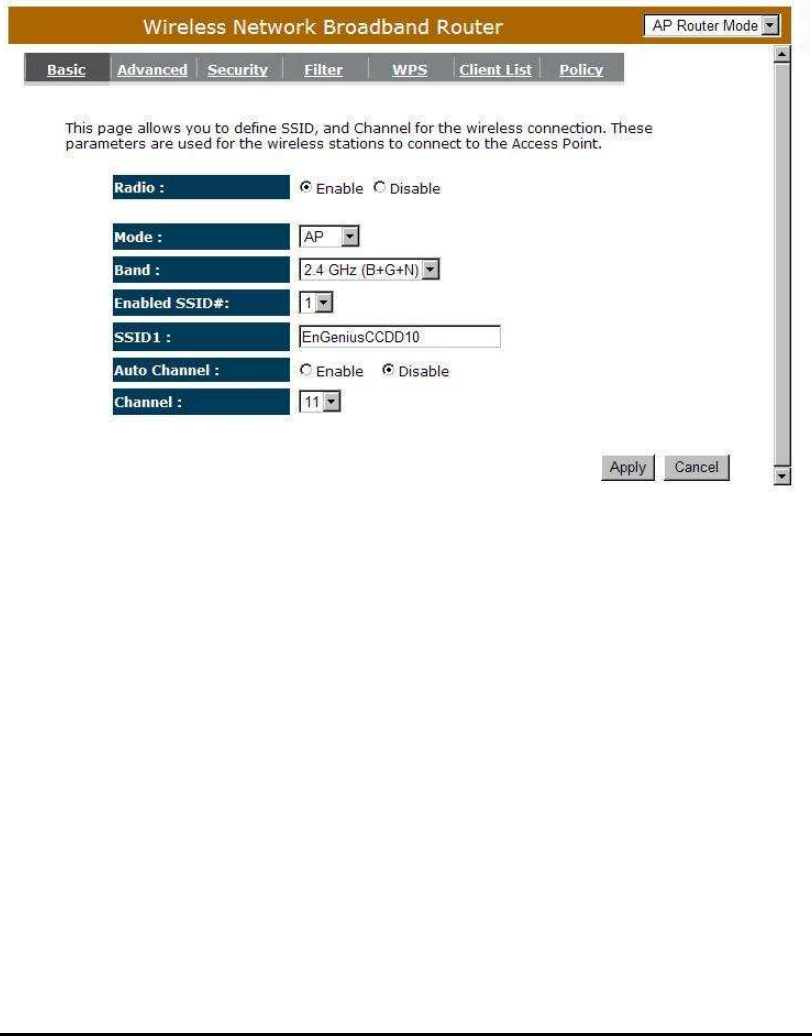
- Basic
In basic setting page, you can set wireless Radio, Mode, Band, SSID, and
Channel.
Radio: You can turn on/off wireless radio. If wireless Radio is off, you cannot
associate with AP through wireless.
Mode: In this device, we support three operation modes which are AP router
and AP route with WDS (we will introduce this function later section).
If you choose AP Router Mode, you can select AP or WDS function in
the drop-down menu.
Band: You can select the wireless standards running on your network
environment.

36
2.4 GHz(B): If all your clients are 802.11b, select this one.
2.4 GHz(N): If all your clients are 802.11n, select this one.
2.4 GHz(B+G): Either an 802.11b or an 802.11g wireless devices are in
your environment.
2.4 GHz(G): If all your clients are 802.11g, select this one.
2.4 GHz(B+G+N): Either 802.11b, 802.11g, or 802.11n wireless devices
are in your environment.
Enable ESSID: We support 4 multiple SSIDs in this device. Please select how
many SSIDs you would like to use in your network environment.
ESSID1~4: ESSID is the name of your wireless network. It might be a unique
name to identify this wireless device in the Wireless LAN. It is case
sensitive and up to 32 printable characters. You might change the
default ESSID for added security.
Auto Channel: Device will search all valid channels, then decide a most clean
channel and change to this channel if you enable this function.
Depend on this function enable or not, you will see different
item below Auto Channel.
Channel: If Auto Channel is disabled, you should choose a static channel and
AP will use this channel to communicate with other clients.
Check Channel Time: If Auto Channel is enabled, you can choose a period
from the drop-down menu. AP will change to a clean
channel periodically.
37
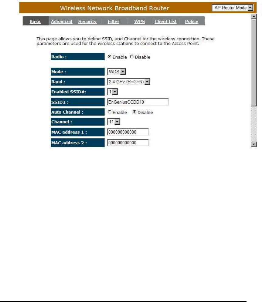
- WDS with AP Router
Wireless Distribution System, a system that enables the wireless
interconnection of access point, allows a wireless network to be expended using
multiple access points without a wired backbone to like them. Each WDS APs
need setting as same channel and encryption type.
MAC address 1~4: Please enter the MAC address of the neighboring APs that
participates in WDS, we support 4 devices now.
Set Security: WDS Security depends on your AP security settings. Note: it
does not support mixed mode such as WPA-PSK/WPA2-PSK
Mixed mode.
38
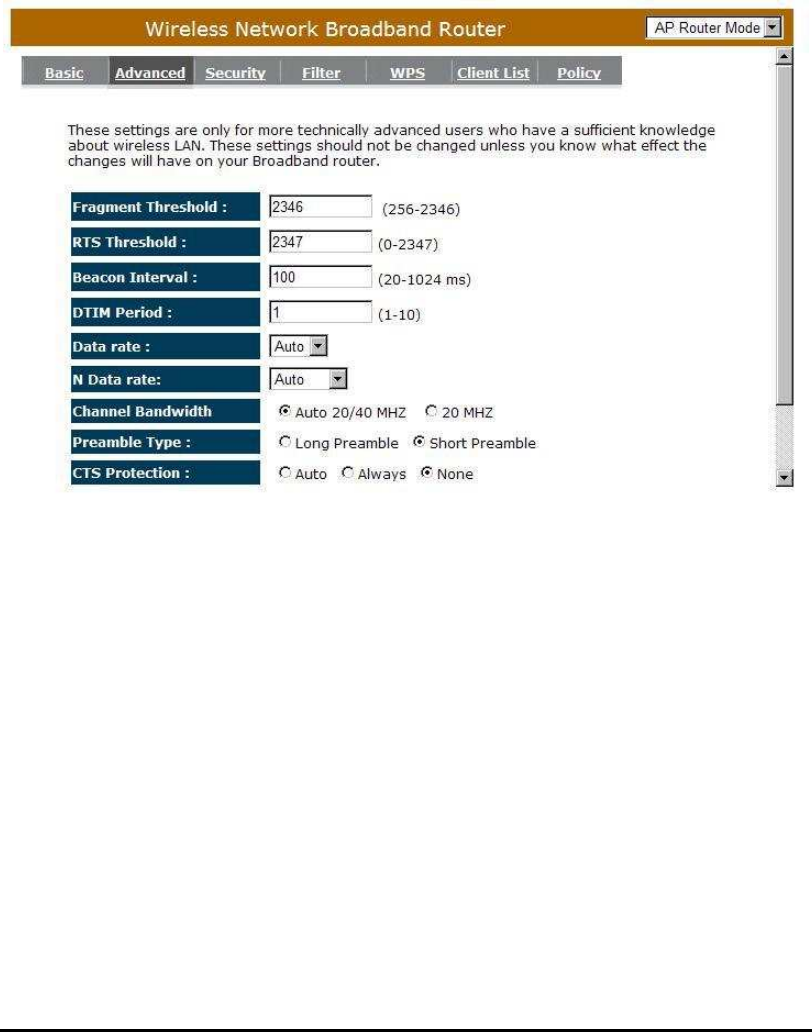
- Advanced
This tab allows you to set the advanced wireless options. The options included
are Authentication Type, Fragment Threshold, RTS Threshold, Beacon Interval,
and Preamble Type. You should not change these parameters unless you know
what effect the changes will have on the router.
Fragment Threshold: This specifies the maximum size of a packet during the
fragmentation of data to be transmitted. If you set this
value too low, it will result in bad performance.
RTS Threshold: When the packet size is smaller than the RTS threshold, the
wireless router will not use the RTS/CTS mechanism to send
this packet.
Beacon Interval: is the interval of time that this wireless router broadcasts a
beacon. A Beacon is used to synchronize the wireless
network.

39
DTIM Period: Enter a value between 1 and 255 for the Delivery Traffic Indication
Message (DTIM). A DTIM is a countdown informing clients of the
next window for listening to broadcast and multicast messages
Data Rate: The “Data Rate” is the rate that this access point uses to transmit
data packets. The access point will use the highest possible
selected transmission rate to transmit the data packets.
N Data Rate: The “Data Rate” is the rate that this access point uses to transmit
data packets for N compliant wireless nodes. Highest to lowest
data rate can be fixed.
Channel Bandwidth: This is the range of frequencies that will be used.
Preamble Type: The “Long Preamble” can provide better wireless LAN
compatibility while the “Short Preamble” can provide better
wireless LAN performance.
CTS Protection: It is recommended to enable the protection mechanism. This
mechanism can decrease the rate of data collision between
802.11b and 802.11g wireless stations. When the protection
mode is enabled, the throughput of the AP will be a little lower
due to a lot of frame-network that is transmitted.
TX Power: This can be set to a bare minimum or maximum power.
40
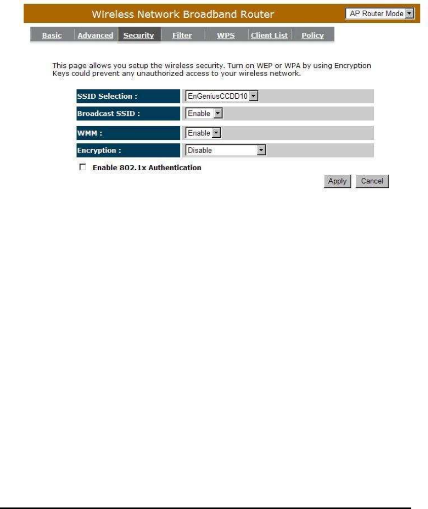
- Security
This Access Point provides complete wireless LAN security functions,
included are WEP, IEEE 802.1x, IEEE 802.1x with WEP, WPA with pre-shared
key and WPA with RADIUS. With these security functions, you can prevent your
wireless LAN from illegal access. Please make sure your wireless stations use
the same security function, and are setup with the same security key.
ESSID Selection: This broadband router support multiple ESSID, you could
select and set up the wanted ESSID.
Broadcast ESSID: If you enabled “Broadcast ESSID”, every wireless station
located within the coverage of this access point can
discover this access point easily. If you are building a
public wireless network, enabling this feature is
recommended. Disabling “Broadcast ESSID” can provide
better security.
WMM: Wi-Fi MultiMedia if enabled supports QoS for experiencing better
audio, video and voice in applications.
Encryption: When you choose to disable encryption, it is very insecure to
operate WBR2100AFN.
41
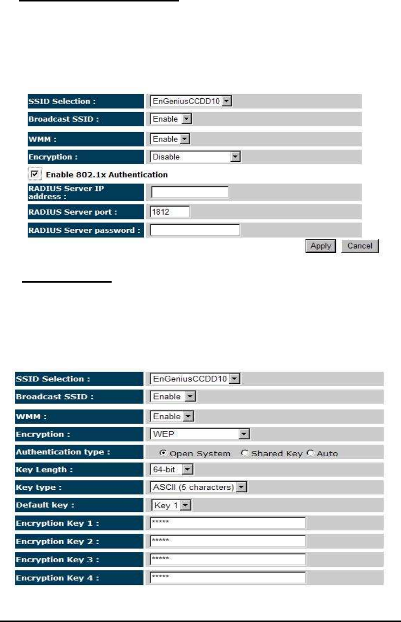
Enable 802.1x Authentication
IEEE 802.1x is an authentication protocol. Every user must use a valid account
to login to this Access Point before accessing the wireless LAN. The
authentication is processed by a RADIUS server. This mode only authenticates
users by IEEE 802.1x, but it does not encrypt the data during communication.
WEP Encryption
When you select 64-bit or 128-bit WEP key, you have to enter WEP keys to
encrypt data. You can generate the key by yourself and enter it. You can enter
four WEP keys and select one of them as a default key. Then the router can
receive any packets encrypted by one of the four keys.

42
Authentication Type: There are two authentication types: "Open System" and
"Shared Key". When you select "Open System",
wireless stations can associate with this wireless router
without WEP encryption. When you select "Shared Key",
you should also setup a WEP key in the "Encryption"
page. After this has been done, make sure the wireless
clients that you want to connect to the device are also
setup with the same encryption key.
Key Length: You can select the WEP key length for encryption, 64-bit or 128-bit.
The larger the key will be the higher level of security is used, but
the throughput will be lower.
Key Type: You may select ASCII Characters (alphanumeric format) or
Hexadecimal Digits (in the "A-F", "a-f" and "0-9" range) to be the
WEP Key.
Key1 - Key4: The WEP keys are used to encrypt data transmitted in the wireless
network. Use the following rules to setup a WEP key on the device.
64-bit WEP:
input 10-digits Hex values (in the "A-F", "a-f" and "0-9" range)
or 5-digit ASCII character as the encryption keys.
128-bit WEP:
input 26-digit Hex values (in the "A-F", "a-f" and "0-9" range)
or 13-digit ASCII characters as the encryption keys.
Click <Apply> at the bottom of the screen to save the above configurations.
You can now configure other sections by choosing Continue, or choose Apply to
apply the settings and reboot the device.
43
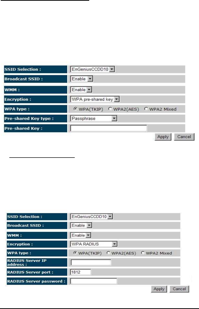
WPA Pre-Shared Key Encryption
Wi-Fi Protected Access (WPA) is an advanced security standard. You can use
a pre-shared key to authenticate wireless stations and encrypt data during
communication. It uses TKIP or CCMP (AES) to change the encryption key
frequently. So the encryption key is not easy to be cracked by hackers. This is
the best security available.
WPA-Radius Encryption
Wi-Fi Protected Access (WPA) is an advanced security standard. You can use
an external RADIUS server to authenticate wireless stations and provide the
session key to encrypt data during communication.
It uses TKIP or CCMP (AES) to change the encryption key frequently. Press
<Apply> button when you are done.
44
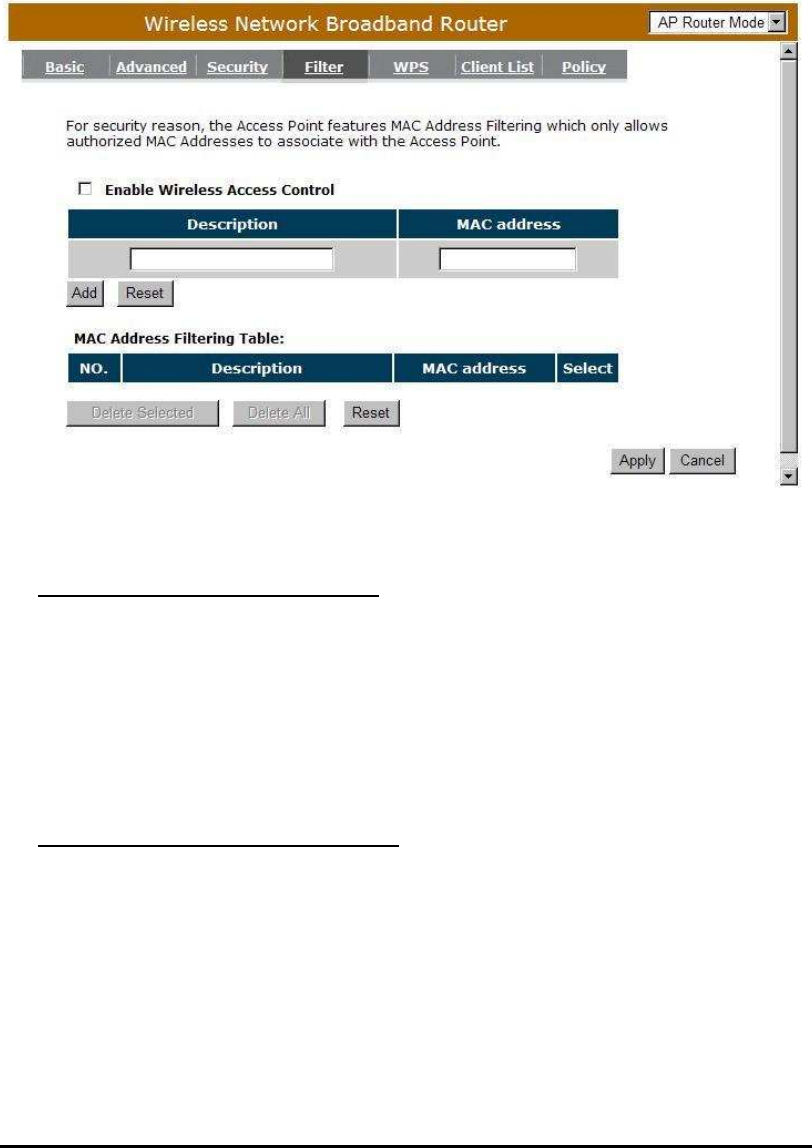
- MAC Address Filtering
This wireless router supports MAC Address Control, which prevents
unauthorized clients from accessing your wireless network.
Enable wireless access control: Enable the wireless access control function
Adding an address into the list
Enter the "MAC Address" and "Comment" of the wireless station to be
added and then click <Add>. The wireless station will now be added into
the "Current Access Control List" below. If you are having any difficulties
filling in the fields, just click "Clear" and both "MAC Address" and
"Comment" fields will be cleared.
Remove an address from the list
If you want to remove a MAC address from the "Current Access Control
List ", select the MAC address that you want to remove in the list and then
click "Delete Selected". If you want to remove all the MAC addresses from
the list, just click the <Delete All> button. Click <Reset> will clear your
current selections.
Click <Apply> at the bottom of the screen to save the above configurations.
45
- Wi-Fi Protected Setup (WPS)
WPS is the simplest way to establish a connection between the wireless clients
and the wireless router. You don’t have to select the encryption mode and fill in a
long encryption passphrase every time when you try to setup a wireless
connection. You only need to press a button on both wireless client and wireless
router, and the WPS will do the rest for you.
The wireless router supports two types of WPS: WPS via Push Button and
WPS via PIN code. If you want to use the Push Button, you have to push a
specific button on the wireless client or in the utility of the wireless client to start
the WPS mode, and switch the wireless router to WPS mode. You can simply
push the WPS button of the wireless router, or click the ‘Start to Process’ button
in the web configuration interface. If you want to use the PIN code, you have to
know the PIN code of the wireless client and switch it to WPS mode, then fill-in
the PIN code of the wireless client through the web configuration interface of the
wireless router.

46
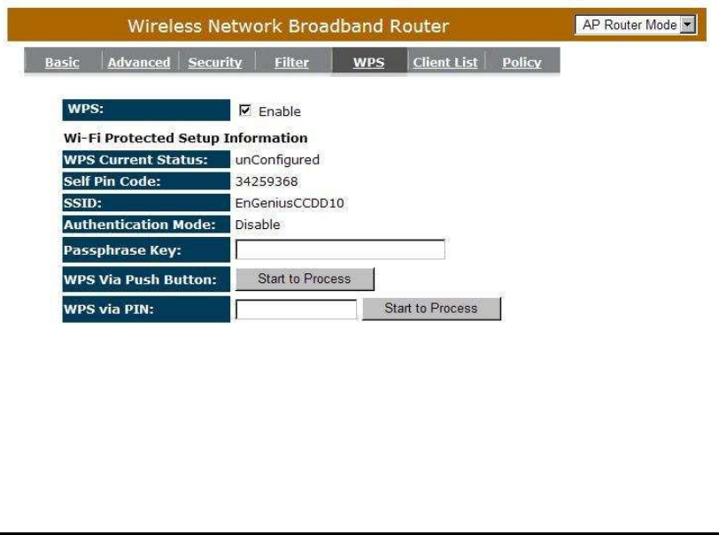
WPS: Check the box to enable WPS function and uncheck it to disable the WPS
function.
WPS Current Status: If the wireless security (encryption) function of this
wireless router is properly set, you’ll see a ‘Configured’
message here. Otherwise, you’ll see ‘UnConfigured’.
Self Pin Code: This is the WPS PIN code of the wireless router. You may need
this information when connecting to other WPS-enabled
wireless devices.
SSID: This is the network broadcast name (SSID) of the router.
Authentication Mode: It shows the active authentication mode for the wireless
connection.
Passphrase Key: It shows the passphrase key that is randomly generated by
the wireless router during the WPS process. You may need
this information when using a device which doesn’t support
WPS.
Interface: If device is set to repeater mode, you can choose “Client” interface to
connect with other AP by using WPS, otherwise you may choose
“AP” interface to do WPS with other clients.
WPS via Push Button: Press the button to start the WPS process. The router
will wait for the WPS request from the wireless devices
within 2 minutes.
WPS via PIN: You can fill-in the PIN code of the wireless device and press the
button to start the WPS process. The router will wait for the WPS
request from the wireless device within 2 minutes.
47
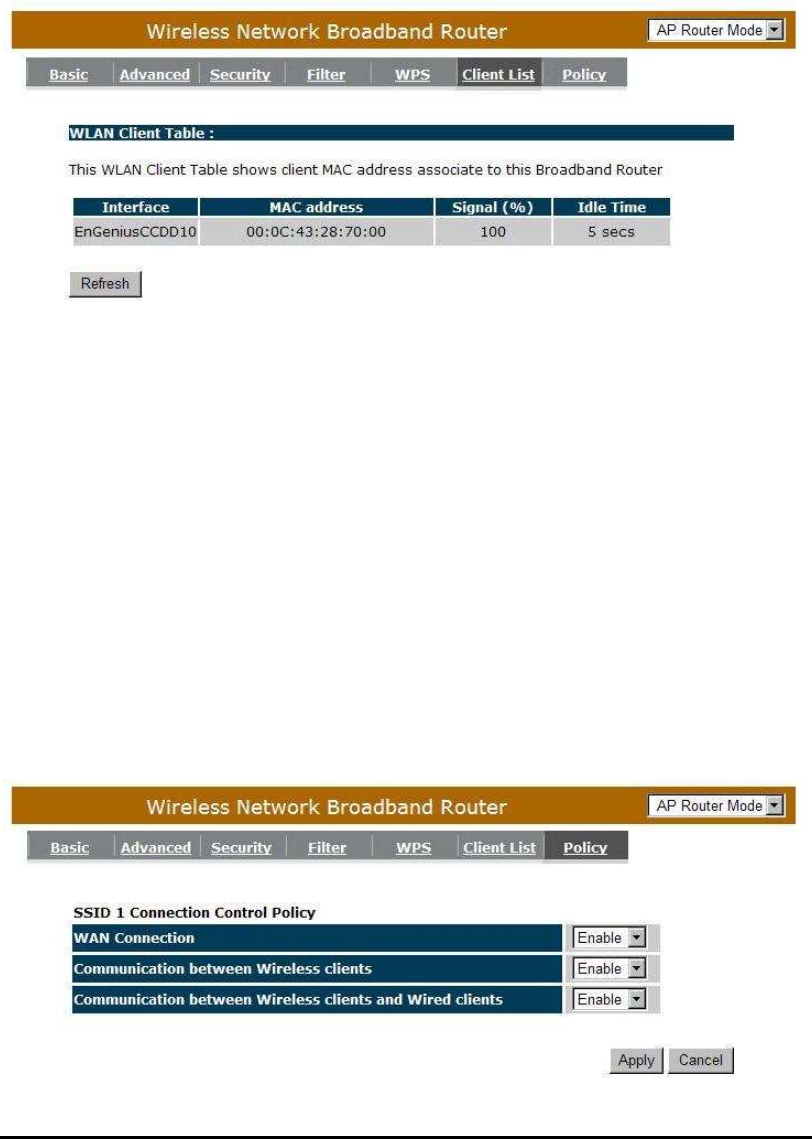
- Client List
This WLAN Client Table shows the Wireless client associate to this Wireless
Router.
- Policy
The Broadband router can allow you to set up the Wireless Access Policy.
WAN Connection: Allow Wireless Client on specific SSID to access WAN port.
Communication between Wireless clients: Allow Wireless Client to
communicate with other Wireless Client on specific SSID.
Communication between Wireless clients and wired clients: Allow Wireless
Client to communicate with other Wireless Client on specific SSID and Wired Client
on the switch. Or Wireless Client will allow to access WAN port only
48
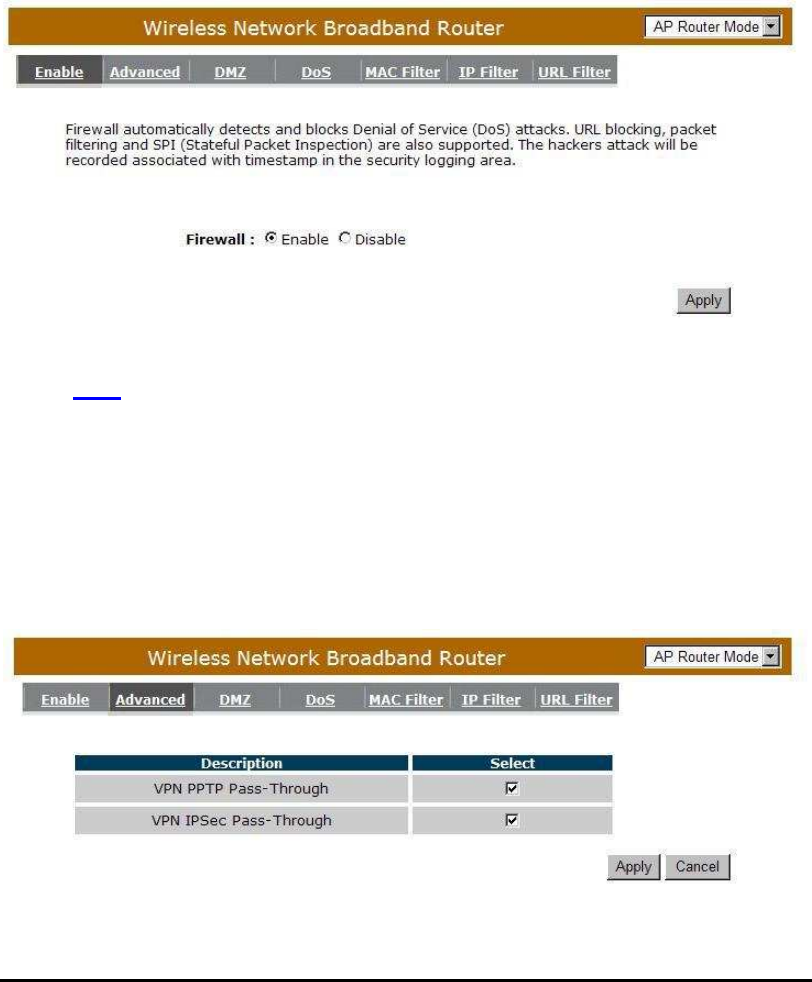
Firewall Settings
The Broadband router provides extensive firewall protection by restricting
connection parameters, thus limiting the risk of hacker attacks, and defending
against a wide array of common Internet attacks. However, for applications that
require unrestricted access to the Internet, you can configure a specific client/server
as a Demilitarized Zone (DMZ).
Note: To enable the Firewall settings select Enable and click Apply
- Advanced
You can allow the VPN packets to pass through this Broadband router.
49
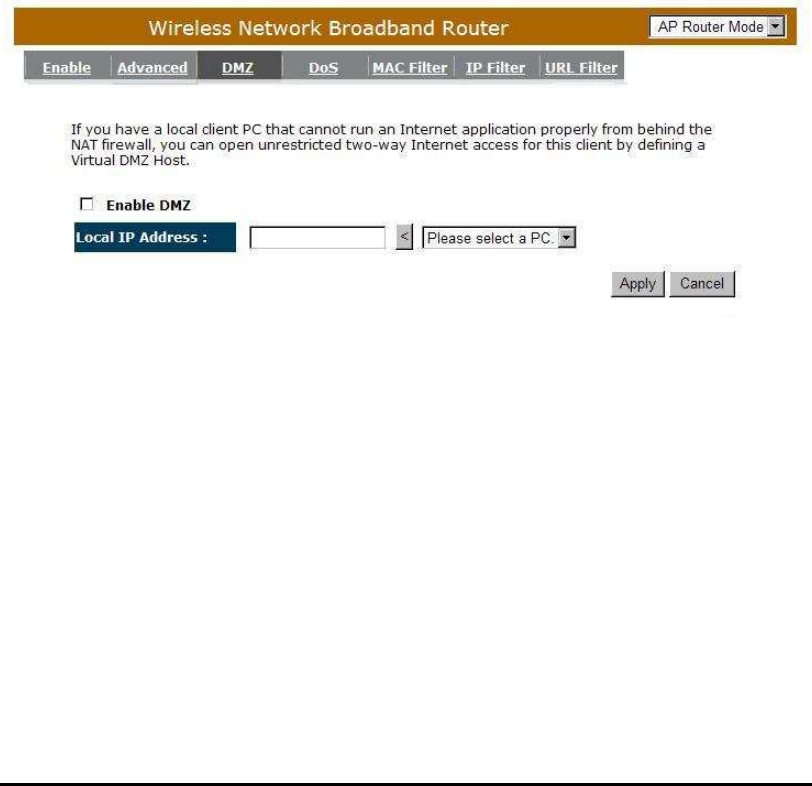
- Demilitarized Zone (DMZ)
If you have a client PC that cannot run an Internet application (e.g. Games)
properly from behind the NAT firewall, then you can open up the firewall
restrictions to unrestricted two-way Internet access by defining a DMZ Host. The
DMZ function allows you to re-direct all packets going to your WAN port IP
address to a particular IP address in your LAN. The difference between the
virtual server and the DMZ function is that the virtual server re-directs a particular
service/Internet application (e.g. FTP, websites) to a particular LAN client/server,
whereas DMZ re-directs all packets (regardless of services) going to your WAN
IP address to a particular LAN client/server.
Enable DMZ: Enable/disable DMZ
LAN IP Address: Fill-in the IP address of a particular host in your LAN Network
that will receive all the packets originally going to the WAN
port/Public IP address above.
Click <Apply> at the bottom of the screen to save the above configurations.
50
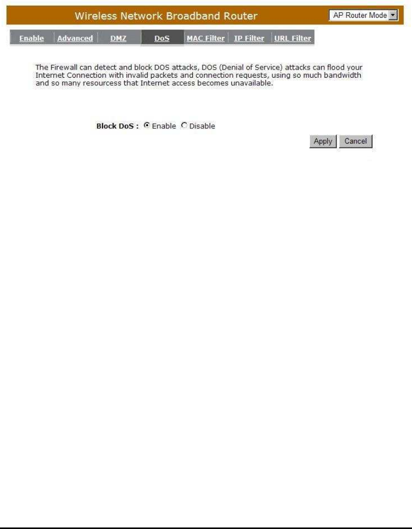
- Denial of Service (DoS)
The Broadband router's firewall can block common hacker attacks, including
Denial of Service, Ping of Death, Port Scan and Sync Flood. If Internet attacks
occur the router can log the events.
Ping of Death: Protections from Ping of Death attack.
Discard Ping From WAN: The router’s WAN port will not respond to any Ping
requests
Port Scan: Protects the router from Port Scans.
Sync Flood: Protects the router from Sync Flood attack.
51
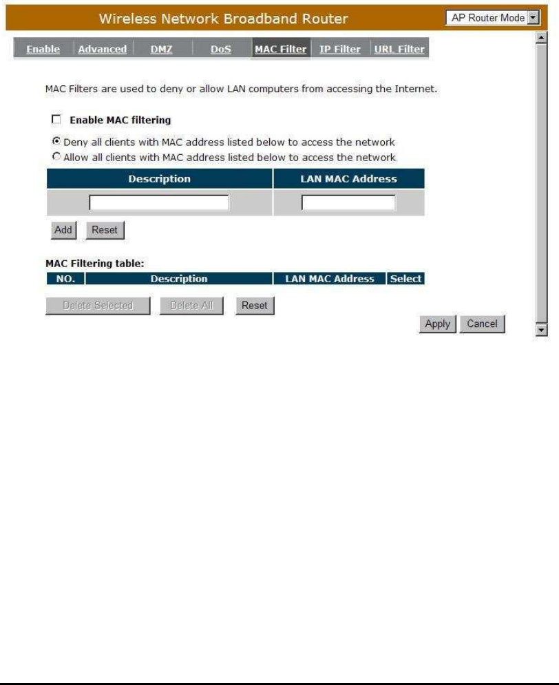
- MAC Filter
If you want to restrict users from accessing certain Internet applications /
services (e.g. Internet websites, email, FTP etc.), and then this is the place to set
that configuration. Access Control allows users to define the traffic type permitted
in your LAN. You can control which PC client can have access to these services.
Enable MAC Filtering: Check to enable or disable MAC Filtering.
Deny: If you select “Deny” then all clients will be allowed to access Internet
accept for the clients in the list below.
Allow: If you select “Allow” then all clients will be denied to access Internet
accept for the PCs in the list below.

52
Add PC MAC Address
Fill in “LAN MAC Address” and <Description> of the PC that is allowed
to access the Internet, and then click <Add>. If you find any typo before
adding it and want to retype again, just click <Reset> and the fields will be
cleared.
Remove PC MAC Address
If you want to remove some PC from the "MAC Filtering Table", select
the PC you want to remove in the table and then click <Delete Selected>.
If you want to remove all PCs from the table, just click the <Delete All>
button. If you want to clear the selection and re-select again, just click
<Reset>.
Click <Apply> at the bottom of the screen to save the above configurations.
53
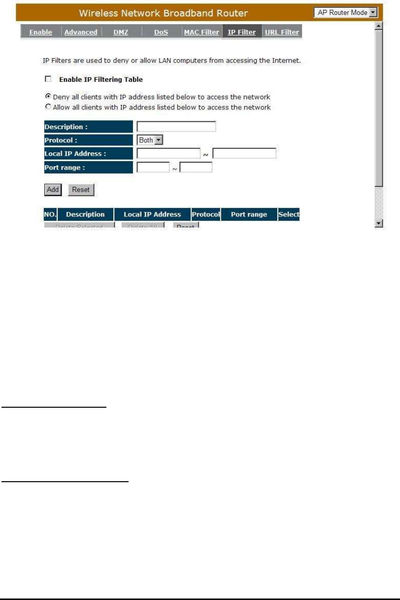
- IP Filter
Enable IP Filtering: Check to enable or disable IP Filtering.
Deny: If you select “Deny” then all clients will be allowed to access Internet
accept for the clients in the list below.
Allow: If you select “Allow” then all clients will be denied to access Internet
accept for the PCs in the list below.
Add PC IP Address
You can click <Add> PC to add an access control rule for users by an IP address
or IP address range.
Remove PC IP Address
If you want to remove some PC IP from the <IP Filtering Table>,
select the PC you want to remove in the table and then click <Delete Selected>. If
you want to remove all PCs from the table, just click the <Delete All> button.
Click <Apply> at the bottom of the screen to save the above configurations.
54
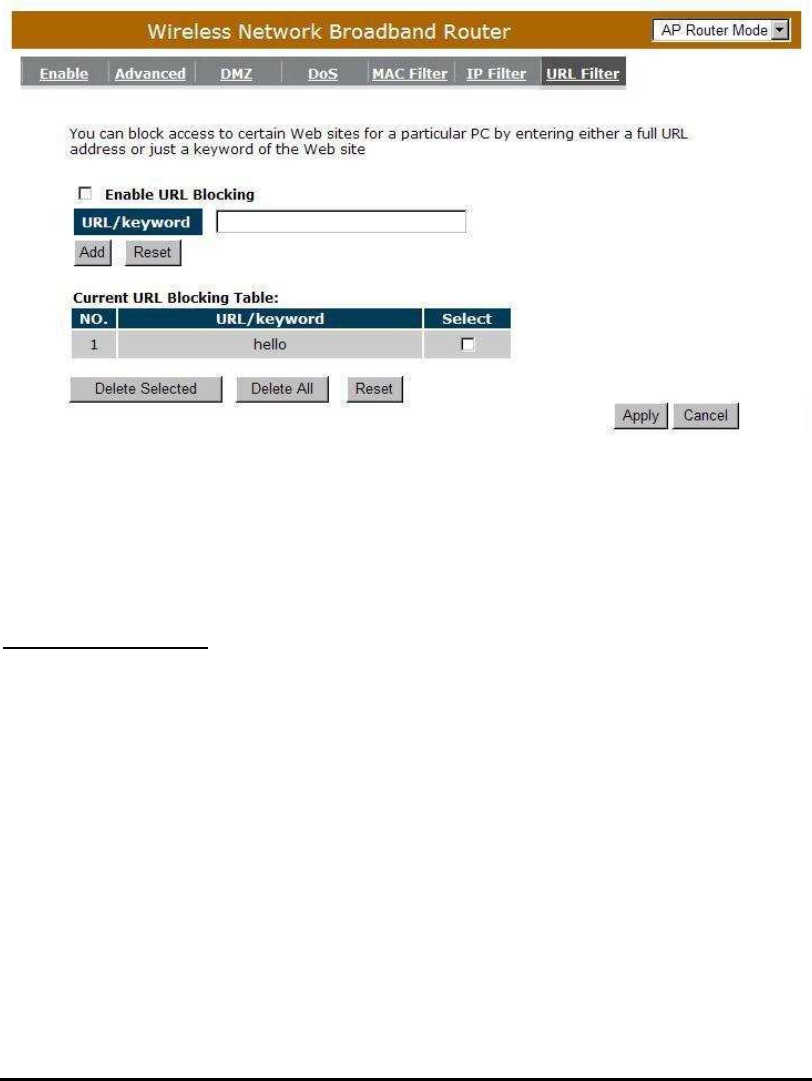
- URL Filter
You can block access to some Web sites from particular PCs by entering a full
URL address or just keywords of the Web site.
Enable URL Blocking: Enable or disable URL Blocking
Add URL Keyword
Fill in “URL/Keyword” and then click <Add>. You can enter the full URL address or
the keyword of the web site you want to block. If you happen to make a mistake and
want to retype again, just click "Reset" and the field will be cleared.

55
Remove URL Keyword
If you want to remove some URL keywords from the "Current URL Blocking
Table", select the URL keyword you want to remove in the table and then click
<Delete Selected>.
If you want remove all URL keywords from the table, click <Delete All> button. If you
want to clear the selection and re-select again, just click <Reset>.
Click <Apply> at the bottom of the screen to save the above configurations
56
Advanced Settings
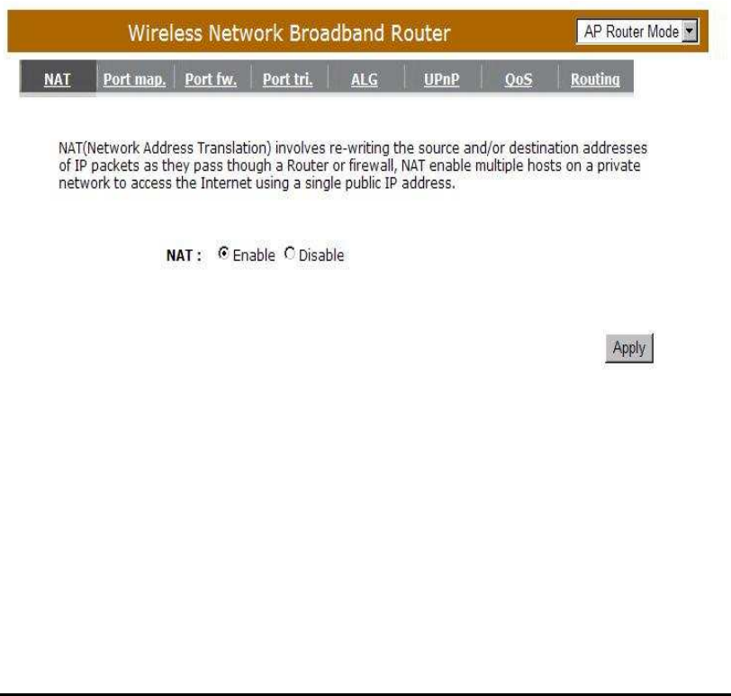
- Network Address Translation (NAT)
Network Address Translation (NAT) allows multiple users at your local site to
access the Internet through a single Public IP Address or multiple Public IP
Addresses. NAT provides Firewall protection from hacker attacks and has the
flexibility to allow you to map Private IP Addresses to Public IP Addresses for key
services such as Websites and FTP. Select Disable to disable the NAT function.
57
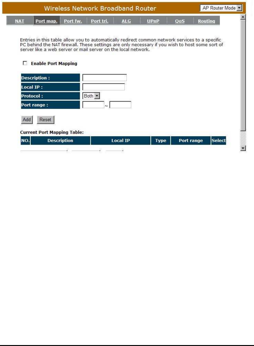
- Port Mapping
Port Mapping allows you to re-direct a particular range of service port numbers
(from the Internet / WAN Port) to a particular LAN IP address. It helps you to host
servers behind the router NAT firewall.
Enable Port Mapping: Enable or disable port mapping function.
Description: description of this setting.
Local IP: This is the local IP of the server behind the NAT firewall.
Type: This is the protocol type to be forwarded. You can choose to forward
“TCP” or “UDP” packets only, or select “BOTH” to forward both “TCP” and
“UDP” packets.
Port Range: The range of ports to be forward to the private IP.
58
Add Port Mapping
Fill in the "Local IP", “Type”, “Port Range” and "Description" of the setting to be
added and then click "Add". Then this Port Mapping setting will be added into the
"Current Port Mapping Table" below. If you find any typo before adding it and want
to retype again, just click <Clear> and the fields will be cleared.
Remove Port Mapping
If you want to remove a Port Mapping setting from the "Current Port Mapping
Table", select the Port Mapping setting that you want to remove in the table and then
click D<Delete Selected>. If you want to remove all Port Mapping settings from the
table, click <Delete All> button. Click <Reset> will clear your current selections.
Click <Apply> at the bottom of the screen to save the above configurations.
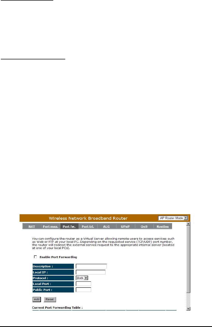
- Port Forwarding (Virtual Server)
Use the Port Forwarding (Virtual Server) function when you want different
servers/clients in your LAN to handle different service/Internet application type (e.g.
Email, FTP, Web server etc.) from the Internet. Computers use numbers called port
numbers to recognize a particular service/Internet application type. The Virtual
Server allows you to re-direct a particular service port number (from the
Internet/WAN Port) to a particular LAN private IP address and its service port
number. (See Glossary for an explanation on Port number).

59
Enable Port Forwarding: Enable or disable Port Forwarding.
Description: The description of this setting.
Local IP / Local Port: This is the LAN Client/Host IP address and Port number
that the Public Port number packet will be sent to.
Type: Select the port number protocol type (TCP, UDP or both). If you are
unsure, then leave it to the default “both” setting. Public Port enters the
service (service/Internet application) port number from the Internet that will
be re-directed to the above Private IP address host in your LAN Network.
Public Port: Port number will be changed to Local Port when the packet enters
your LAN Network.
Add Port Forwarding
Fill in the "Description" , "Local IP", "Local Port", "Type" and “Public
Port” of the setting to be added and then click <Add> button. Then this
Virtual Server setting will be added into the "Current Port Forwarding
Table" below. If you find any typo before adding it and want to retype again,
just click <Clear> and the fields will be cleared.
Remove Port Forwarding
If you want to remove Port Forwarding settings from the "Current Port
Forwarding Table", select the Port Forwarding settings you want to
remove in the table and then click "Delete Selected". If you want to remove
all Port Forwarding settings from the table, just click the <Delete All>
button. Click <Reset> will clear your current selections.
Click <Apply> at the bottom of the screen to save the above configurations.
60
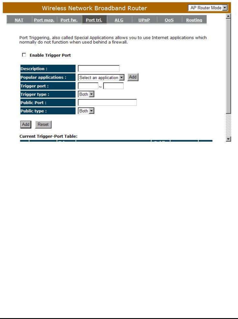
- Port Triggering (Special Applications)
Some applications require multiple connections, such as Internet games, video
Conferencing, Internet telephony and others. In this section you can configure
the router to support multiple connections for these types of applications.
Enable Trigger Port: Enable or disable the Port Trigger function.
Trigger Port: This is the outgoing (Outbound) range of port numbers for this
particular application.
Trigger Type: Select whether the outbound port protocol is “TCP”, “UDP” or
“BOTH”.
Public Port: Enter the In-coming (Inbound) port or port range for this type of
application (e.g. 2300-2400, 47624)
Public Type: Select the Inbound port protocol type: “TCP”, “UDP” or “BOTH”

61
Popular Applications: This section lists the more popular applications that
require multiple connections. Select an application
from the Popular Applications selection. Once you
have selected an application, select a location (1-5) in
the Copy to selection box and then click the Copy to
button. This will automatically list the Public Ports
required for this popular application in the location (1-5)
you specified.
Add Port Triggering
Fill in the "Trigger Port", "Trigger Type”, “Public Port”, "Public Type",
"Public Port" and "Description" of the setting to be added and then Click
<Add>. The Port Triggering setting will be added into the "Current Trigger-
Port Table" below. If you happen to make a mistake, just click <Clear> and
the fields will be cleared.
Remove Port Triggering
If you want to remove Special Application settings from the "Current
Trigger-Port Table", select the Port Triggering settings you want to remove
in the table and then click <Delete Selected>. If you want remove all Port
Triggering settings from the table, just click the <Delete All> button. Click
<Reset> will clear your current selections.
62
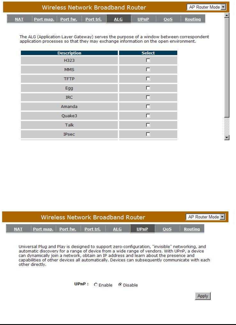
- Application Layer Gateway (ALG)
You can select applications that need ALG support. The router will let the selected
application to correctly pass through the NAT gateway.
- UPNP
With UPnP, all PCs in you Intranet will discover this router automatically. So,
you don’t have to configure your PC and it can easily access the Internet through
this router.

63
Enable/Disable UPnP: You can enable or Disable the UPnP feature here. After
you enable the UPnP feature, all client systems that
support UPnP, like Windows XP, can discover this
router automatically and access the Internet through this
router without having to configure anything. The NAT
Traversal function provided by UPnP can let
applications that support UPnP connect to the internet
without having to configure the virtual server sections.
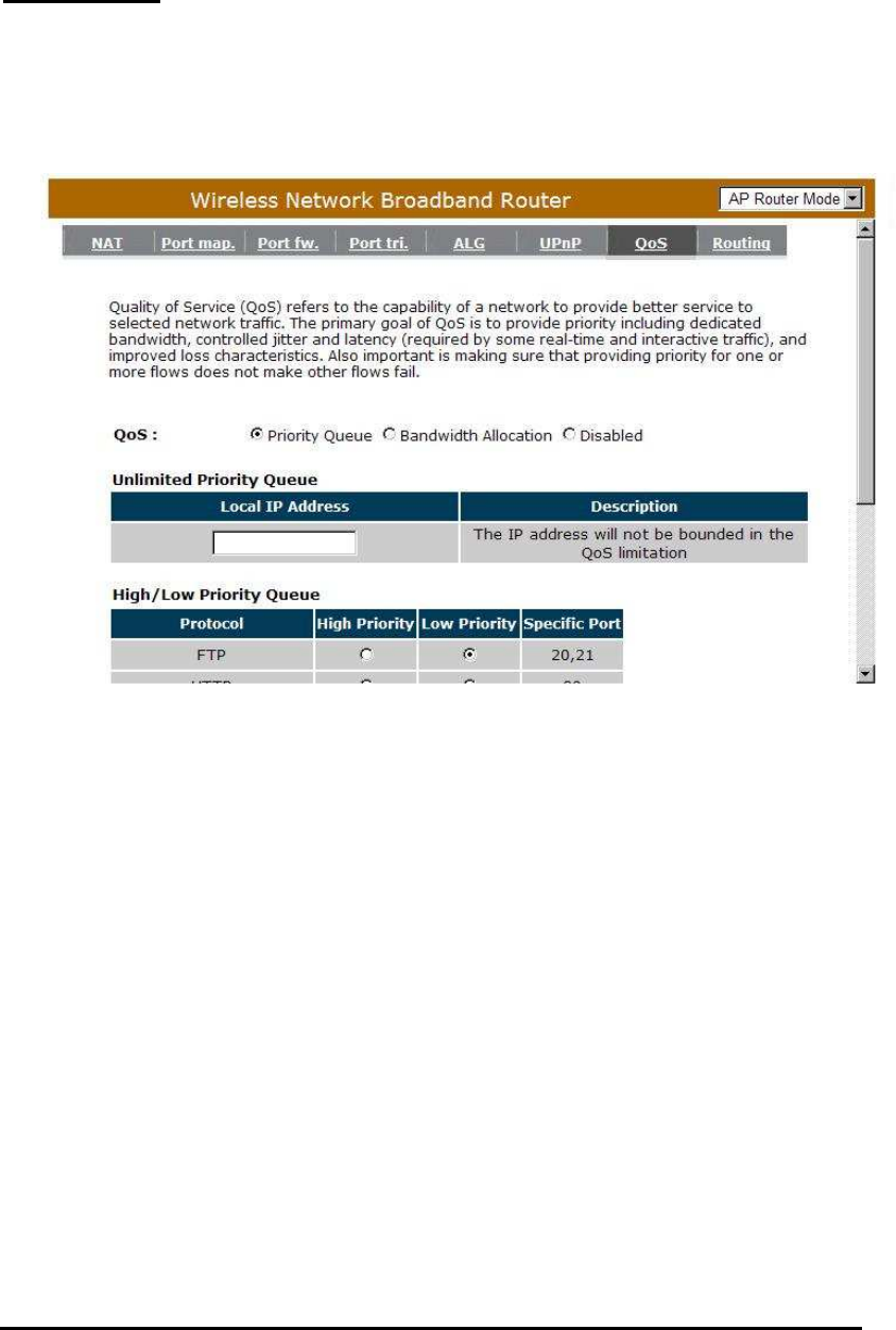
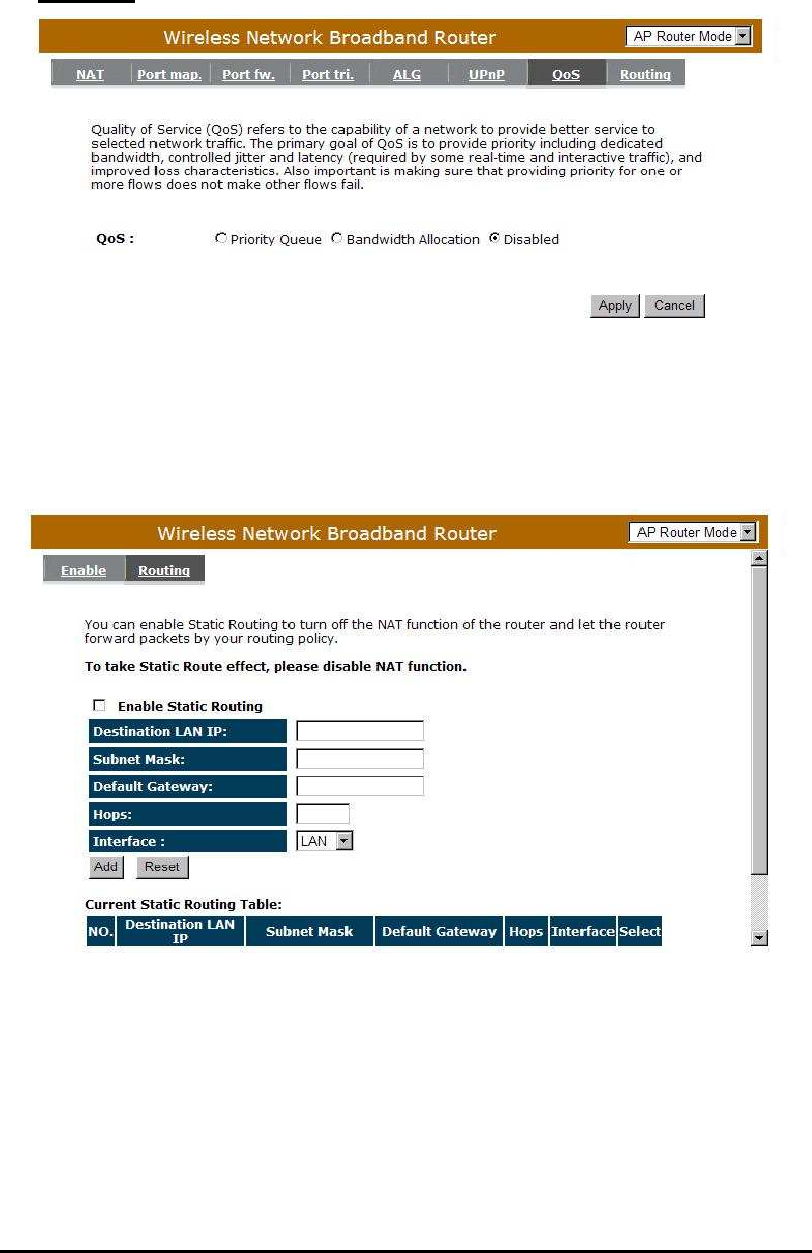
- Quality of Service (QoS)
QoS can let you classify Internet application traffic by source/destination IP
address and port number. You can assign priority for each type of application
and reserve bandwidth for it. The packets of applications with higher priority will
always go first. Lower priority applications will get bandwidth after higher priority
applications get enough bandwidth. This can let you have a better experience in
using critical real time services like Internet phone, video conference …etc. All
the applications not specified by you are classified as rule “Others”. The rule with
a smaller priority number has a higher priority; the rule with a larger priority
number has a lower priority. You can adjust the priority of the rules by moving
them up or down.
64
Priority Queue
This can put the packets of specific protocols in High/Low Queue. The
packets in High Queue will process first.
Unlimited Priority Queue: The LAN IP address will not be bounded in the QoS
limitation.
High/Low Priority Queue: This can put the packets in the protocol and port
range to High/Low QoS Queue.
65
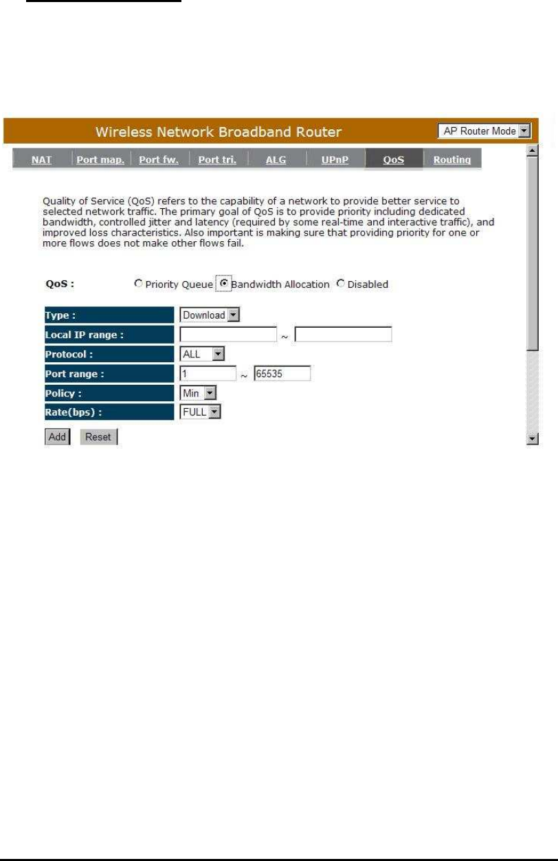
Bandwidth Allocation:
This can reserve / limit the throughput of specific protocols and port range.
You can set the upper bound and Lower bound.
Type: Specify the direction of packets. Upload, download or both.
IP range: Specify the IP address range. You could also fill one IP address
Protocol: Specify the packet type. The default ALL will put all packets in the QoS
priority Queue.
Port range: Specify the Port range. You could also fill one Port.
Policy: Specify the policy the QoS, Min option will reserve the selected data rate
in QoS queue. Max option will limit the selected data rate in QoS queue.
Rate: The data rate of QoS queue.
66
Disabled: This could turn off QoS feature.
- Routing
You can set enable Static Routing to let the router forward packets by your routing
policy.
Destination LAN IP: Specify the destination LAN IP address of static routing rule.
Subnet Mask: Specify the Subnet Mask of static routing rule.
Default Gateway: Specify the default gateway of static routing rule.
Hops: Specify the Max Hops number of static routing rule.
Interface: Specify the Interface of static routing rule.
67
TOOLS Settings
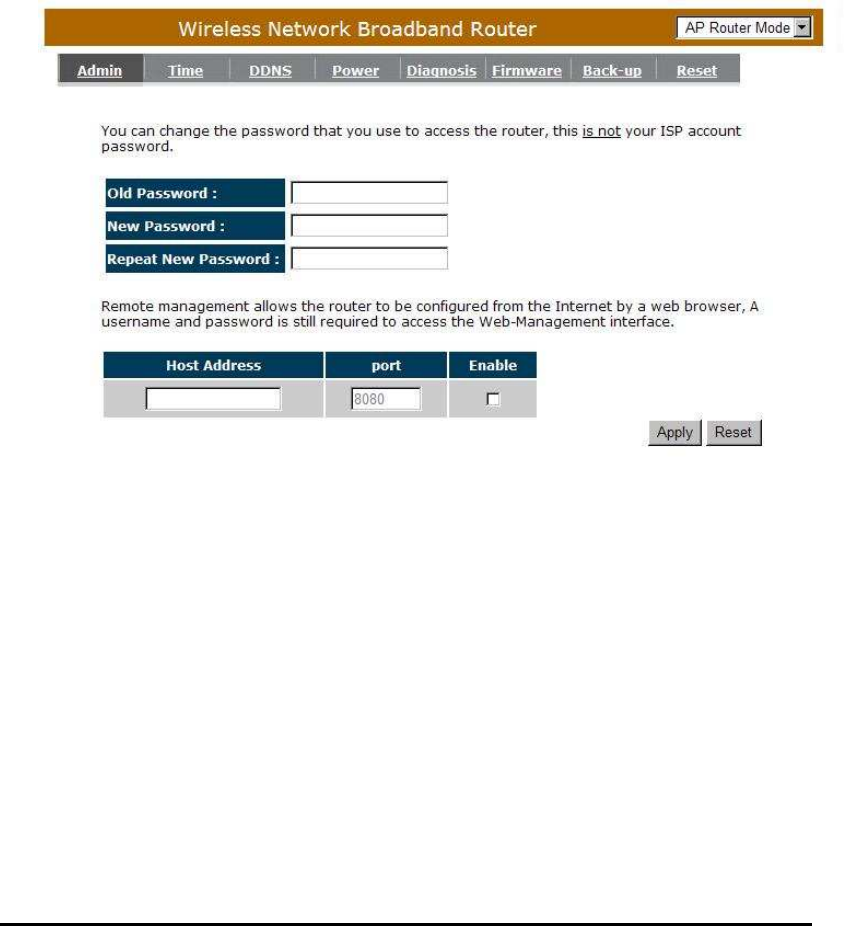
- Admin
You can change the password required to log into the broadband router's
system web-based management. By default, the password is: admin. Passwords
can contain 0 to 12 alphanumeric characters, and are case sensitive.
Old Password: Fill in the current password to allow changing to a new password.
New Password: Enter your new password and type it again in Repeat New
Password for verification purposes

68
Remote managemen
t
This allows you to designate a host in the Internet the ability to configure
the Broadband router from a remote site. Enter the designated host IP
Address in the Host IP Address field.
Host Address: This is the IP address of the host in the Internet that will have
management/configuration access to the Broadband router from
a remote site. If the Host Address is left 0.0.0.0 this means
anyone can access the router’s web-based configuration from a
remote location, providing they know the password.
Port: The port number of the remote management web interface.
Enabled: Check to enable the remote management function.
Click <Apply> at the bottom of the screen to save the above configurations.
69
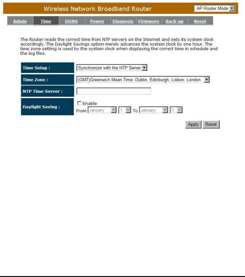
- Time
The Time Zone allows your router to reference or base its time on the settings
configured here, which will affect functions such as Log entries and Firewall
settings.
Time Setup:
Synchronize with the NTP server
Time Zone: Select the time zone of the country you are currently in. The router
will set its time based on your selection.
NTP Time Server: The router can set up external NTP Time Server.
Daylight Savings: The router can also take Daylight Savings into account. If you
wish to use this function, you must select the Daylight
Savings Time period and check/tick the enable box to enable
your daylight saving configuration.
Click <Apply> at the bottom of the screen to save the above configurations.
70
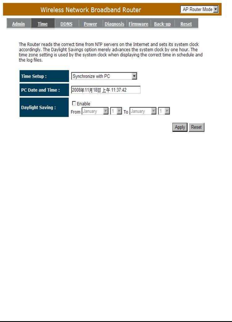
Synchronize with PC
You could synchronize timer with your Local PC time.
PC Date and Time: This field would display the PC date and time.
Daylight Savings: The router can also take Daylight Savings into account. If you
wish to use this function, you must select the Daylight
Savings Time period and check/tick the enable box to enable
your daylight saving configuration.
Click <Apply> at the bottom of the screen to save the above configurations.
71
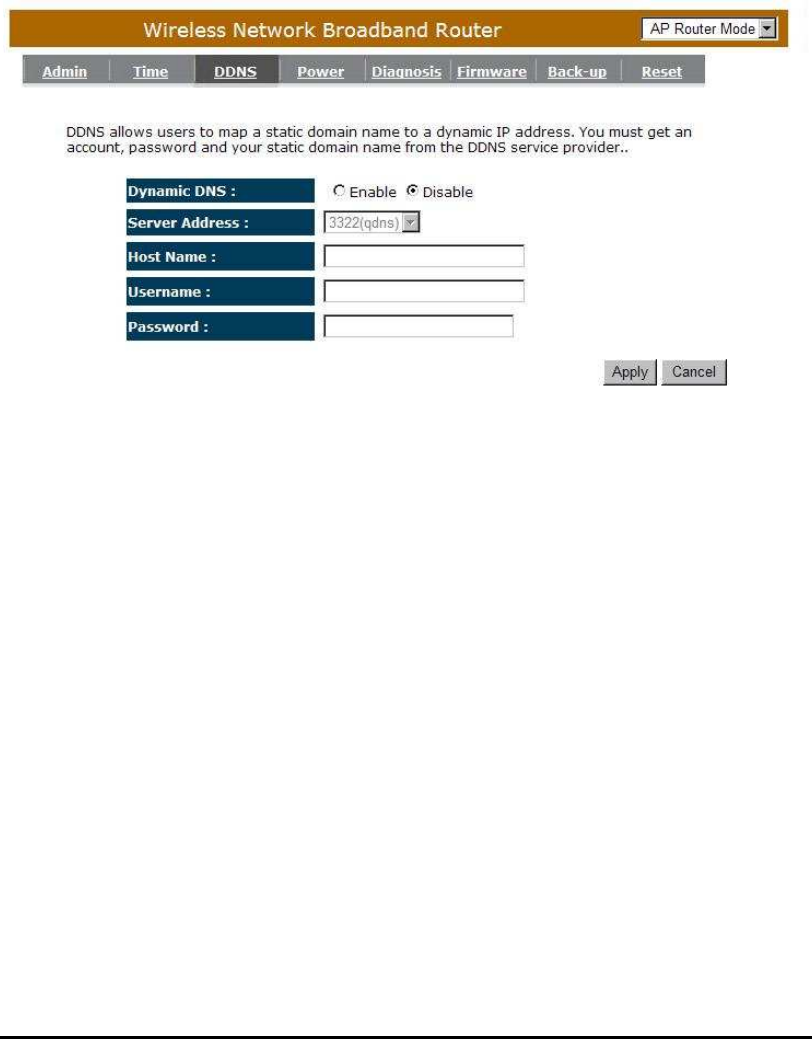
- DDNS
DDNS allows you to map the static domain name to a dynamic IP address.
You must get an account, password and your static domain name from the
DDNS service providers. This router supports DynDNS, TZO and other common
DDNS service providers.
Enable/Disable DDNS: Enable or disable the DDNS function of this router
Server Address: Select a DDNS service provider
Host Name: Fill in your static domain name that uses DDNS.
Username: The account that your DDNS service provider assigned to you.
Password: The password you set for the DDNS service account above
Click <Apply> at the bottom of the screen to save the above configurations.
72
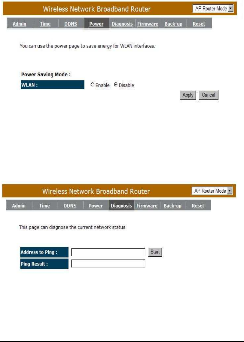
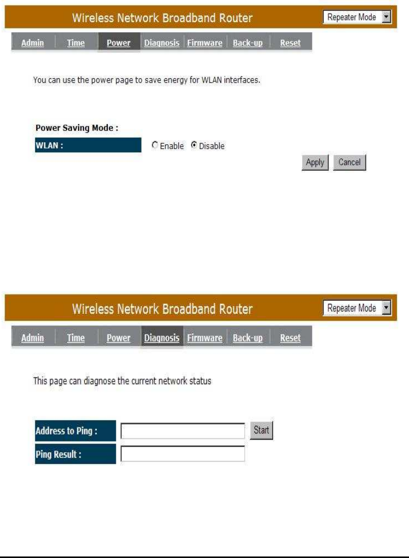
- Power
Saving power in WLAN mode can be enabled / disabled in this page.
- Diagnosis
This page could let you diagnosis your current network status.
73
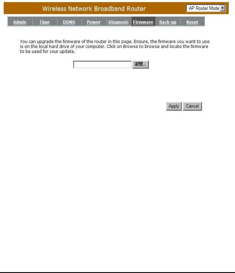
- Firmware
This page allows you to upgrade the router’s firmware. To upgrade the
firmware of your Broadband router, you need to download the firmware file to
your local hard disk, and enter that file name and path in the appropriate field on
this page. You can also use the Browse button to find the firmware file on your
PC.
Once you’ve selected the new firmware file, click <Apply> at the bottom of the
screen to start the upgrade process
74
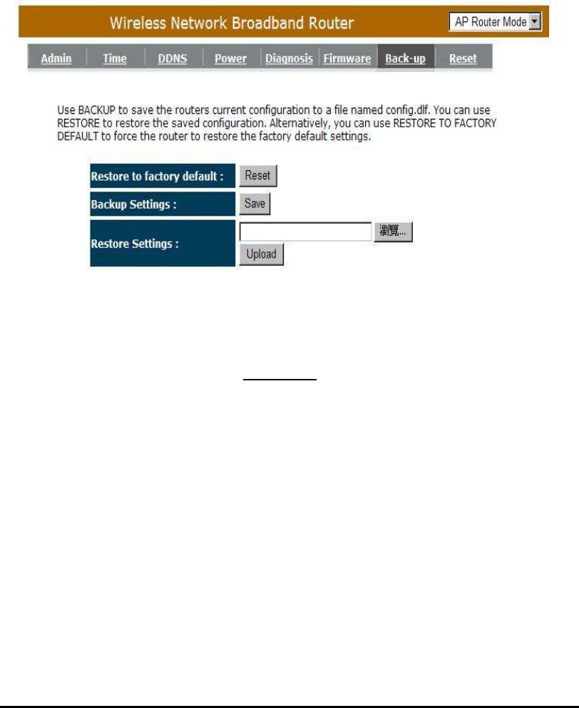
- Back-up
This page allows you to save the current router configurations. When you save the
configurations, you also can re-load the saved configurations into the router through
the Restore Settings. If extreme problems occur you can use the Restore to
Factory Defaults to set all configurations to its original default settings.
Backup Settings: This can save the Broadband router current configuration to a
file named "config.bin" on your PC. You can also use the
<Upload> button to restore the saved configuration to the
Broadband router. Alternatively, you can use the "Restore to
Factory Defaults" tool to force the Broadband router to
perform a power reset and restore the original factory settings.
75
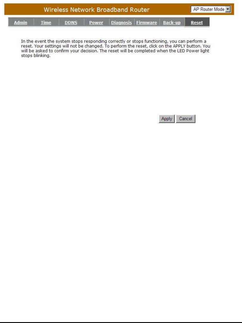
- Reset
You can reset the broadband router when system stops responding correctly
or stop functions.
76
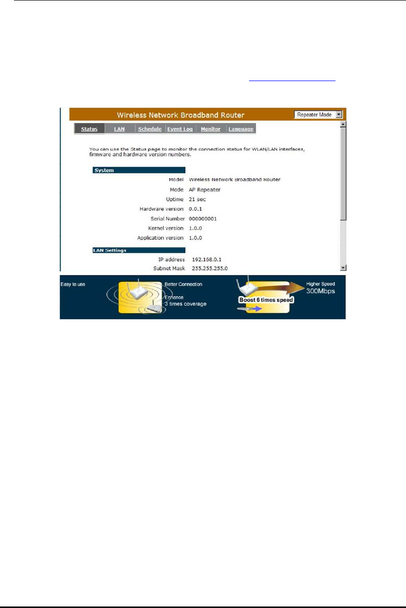
13 Repeater Mode
Repeater mode has limited settings compared to the AP mode. Choose
“Repeater mode” on the top right corner of the configuration page.
System restarts and connects to the IP address http://192.168..0.1
You will see the configuration homepage under “REPEATER” mode now.
System
- Status
System status section allows you to monitor the current status of your router. You
can use the status page to quickly see if you have any updated firmware available
(bug fixes, updates). You can navigate from this page with a few interesting options
for reminding or skipping this page forever & so forth.
Once you click on <OK> button to go to the requested page, you can see the
status page of the WBR2100AFN.
You can see the UP time, hardware information, serial number as well as firmware
version information.
77
LAN Settings: This page displays the Broadband router LAN port’s current LAN &
WLAN information. It also shows whether the DHCP Server function is enabled
/ disabled. Wireless configuration details such as SSID, Security settings,
BSSID, Channel number, mode of operation are briefly shown.
WLAN Settings: View Broadband router’s current configuration settings. Device
Status displays the configuration settings you’ve configured in the Wizard /
Basic Settings / Wireless Settings section
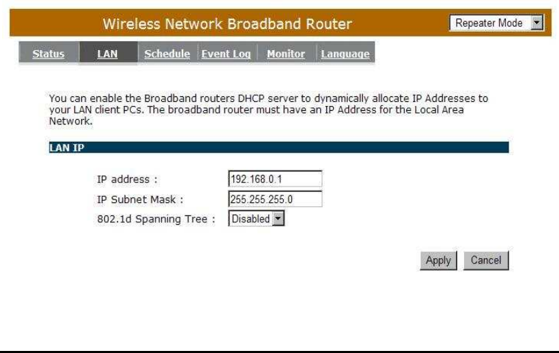
- LAN
The LAN Tabs reveals LAN settings which can be altered at will. If you are an
entry level user, try accessing a website from your browser. If you can access
website without a glitch, just do not change any of these settings.
Click <Apply> at the bottom of this screen to save the changed configurations.
78
IP address: It is the router’s LAN IP address (Your LAN clients default gateway IP
address). It can be changed based on your own choice.
IP Subnet Mask: Specify a Subnet Mask for your LAN segment.
802.1d Spanning Tree: This is disabled by default. If 802.1d Spanning Tree
function is enabled, this router will use the spanning
tree protocol to prevent network loops.
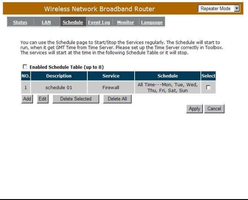
- Schedule
Add schedule, edit schedule options allow configuration of power savings services.
Fill in the schedule and select type of service. Click <Apply> to implement the
settings.
The schedule table lists the pre-schedule service-runs. You can select any of
them using the check box.
79
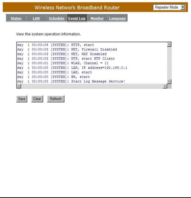
- Event Log
View operation log of WBR2100AFN. This page shows the current system log
of the Broadband router. It displays any event occurred after system start up. At
the bottom of the page, the system log can be saved <Save> to a local file for
further processing or the system log can be cleared <Clear> or it can be
refreshed <Refresh> to get the most updated information. When the system is
powered down, the system log will disappear if not saved to a local file.
80
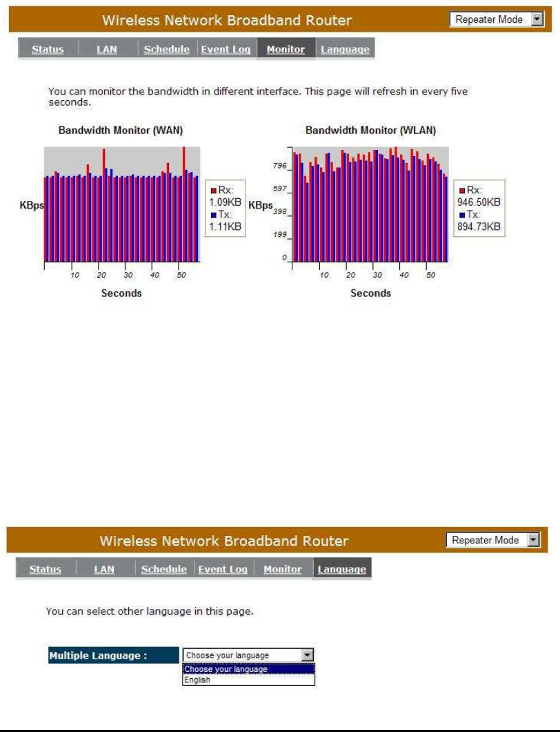
- Monitor
Show the network packets histogram for network connection on WAN, LAN &
WLAN. Auto refresh keeps information updated frequently.
- Language
This Wireless Router support multiple language of web pages, you could select
your native language here.
81
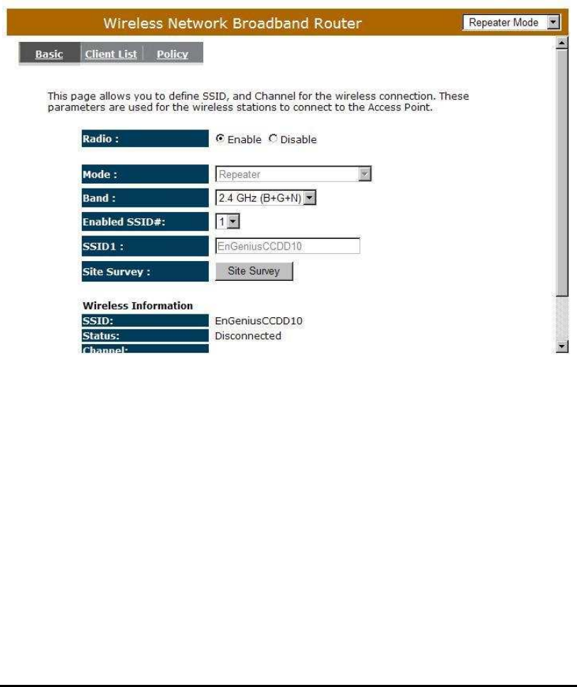
Wireless
-Basic
You can set parameters that are used for the wireless stations to connect to this
router. The parameters include Mode, ESSID, Channel Number and Associated
Client.
Radio: Enable or Disable Wireless function
Band: Allows you to set the AP fixed at 802.11b, 802.11g or 802.11n mode. You
can also select B+G mode to allow 802.11b and 802.11g clients at the
same time.
Enable ESSID: You can specify the maximum ESSID number.
ESSID1~3: Allow you to specify ESSID of WLAN.
82
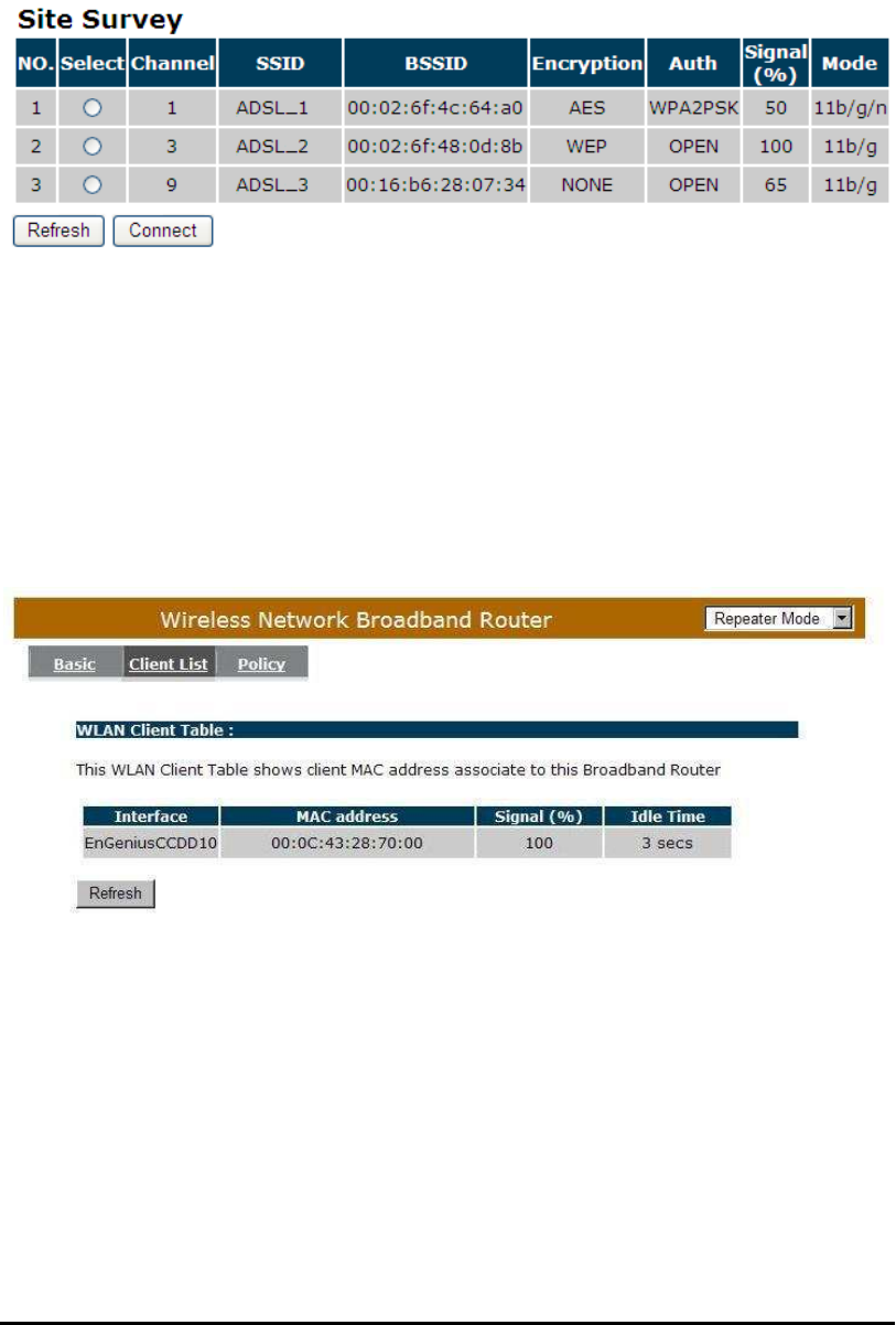
Site Survey: You can scan the current Wireless Access Point and connect on it.
-Clint List
This WLAN Client Table shows the Wireless client associate to this Wireless
Router.
83
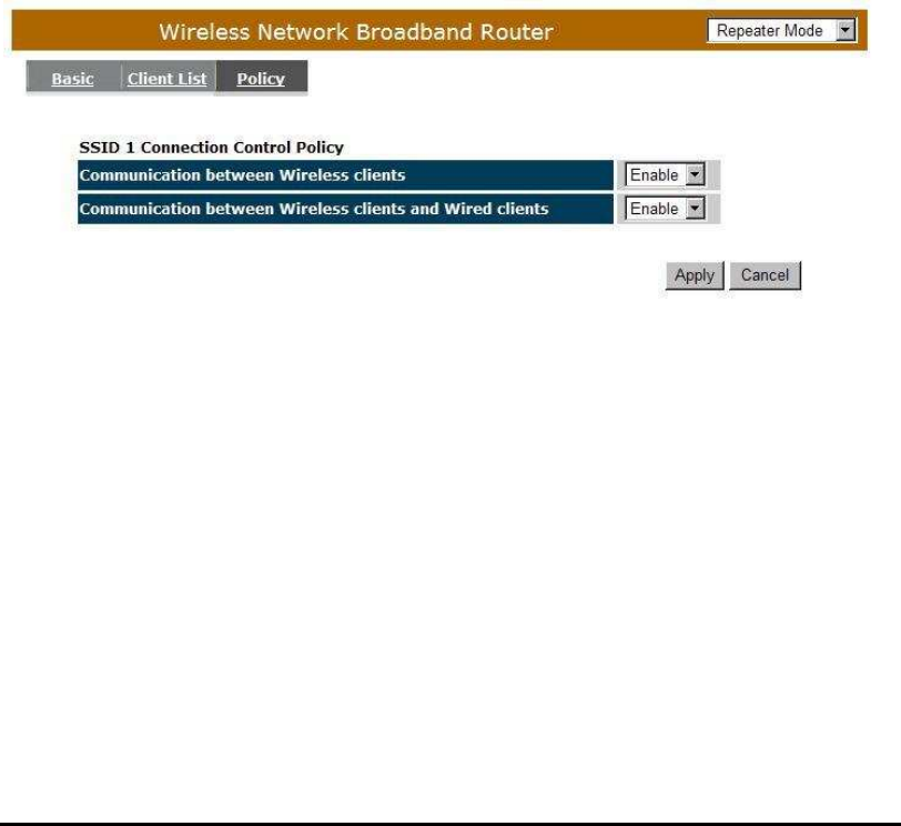
-Policy
The Broadband router can allow you to set up the Wireless Access Policy.
Communication between Wireless clients:
Allow Wireless Client to communicate with other Wireless Client on specific SSID.
Communication between Wireless clients and wired clients:
Allow Wireless Client to communicate with other Wireless Client on specific
SSID and Wired Client on the switch. Or Wireless Client will allow to access WAN
port only
84
Tools
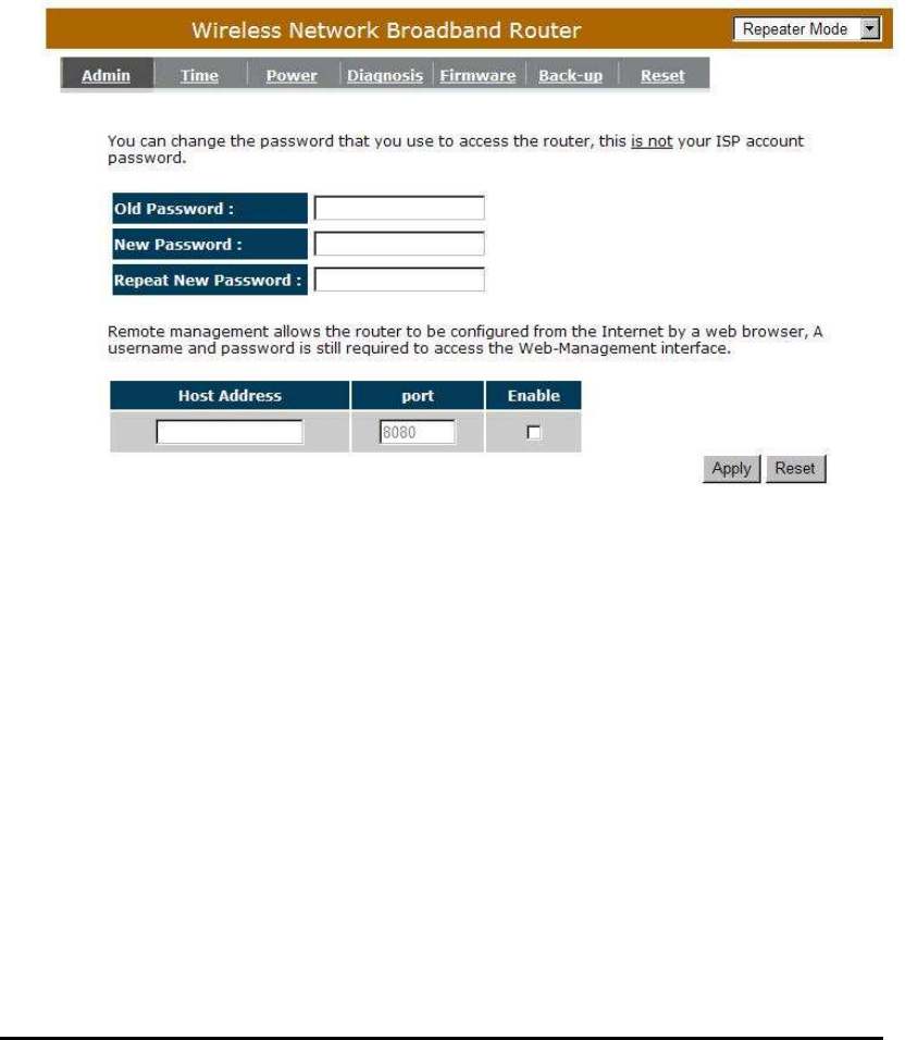
- Admin
You can change the password required to log into the broadband router's
system web-based management. By default, the password is: admin. Passwords
can contain 0 to 12 alphanumeric characters, and are case sensitive.
Old Password: Fill in the current password to allow changing to a new password.
New Password: Enter your new password and in Repeat New Password for
verification purposes
Click <Apply> at the bottom of the screen to save the above configurations

85
Remote managemen
t
This allows you to designate a host in the Internet the ability to configure the
Broadband router from a remote site. Enter the designated host IP Address in the
Host IP Address field.
Host Address: This is the IP address of the host in the Internet that will have
management/configuration access to the Broadband router from
a remote site. If the Host Address is left 0.0.0.0 this means
anyone can access the router’s web-based configuration from a
remote location, providing they know the password.
Port: The port number of the remote management web interface.
Enabled: Check to enable the remote management function.
Click <Apply> at the bottom of the screen to save the above configurations.
86
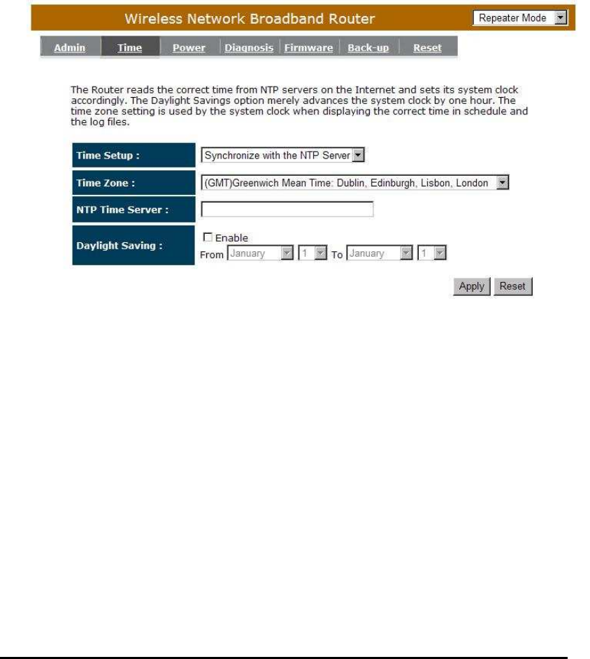
- Time
The Time Zone allows your router to reference or base its time on the settings
configured here, which will affect functions such as Event Log entries and
Schedule settings.
Time Setup:
Synchronize with the NTP server
Time Zone: Select the time zone of the country you are currently in. The
router will set its time based on your selection.
NTP Time Server: This accept local the IP Address of Local NTP Time
Server Address.
Daylight Savings: The router can also take Daylight Savings into account.
If you wish to use this function, you must select the
Daylight Savings Time period and check/tick the enable
box to enable your daylight saving configuration.
Click <Apply> at the bottom of the screen to save the above configurations
87
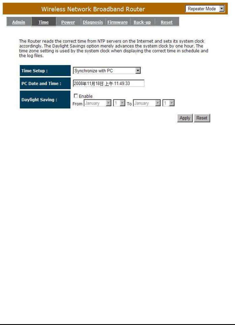
Synchronize with PC
You could synchronize timer with your Local PC time.
PC Date and Time: This field would display the PC date and time.
Daylight Savings: The router can also take Daylight Savings into account. If you
wish to use this function, you must select the Daylight Savings
Time period and check/tick the enable box to enable your
daylight saving configuration.
Click <Apply> at the bottom of the screen to save the above configurations.
88
- Power
Saving power in WLAN mode can be enabled / disabled in this page.
- Diagnosis
This page could let you diagnosis your current network status.
89
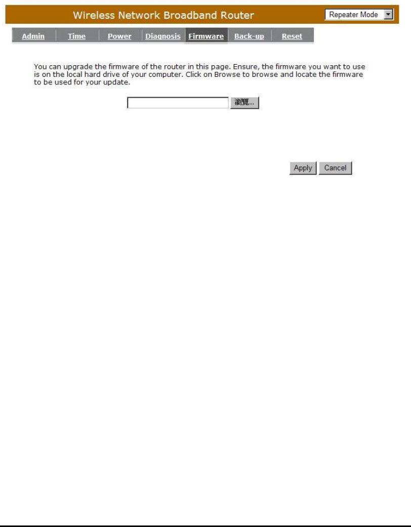
- Firmware
This page allows you to upgrade the router’s firmware. To upgrade the firmware
of your Broadband router, you need to download the firmware file to your local hard
disk, and enter that file name and path in the appropriate field on this page. You can
also use the Browse button to find the firmware file on your PC.
Once you’ve selected the new firmware file, click <Apply> at the bottom of the
screen to start the upgrade process
90
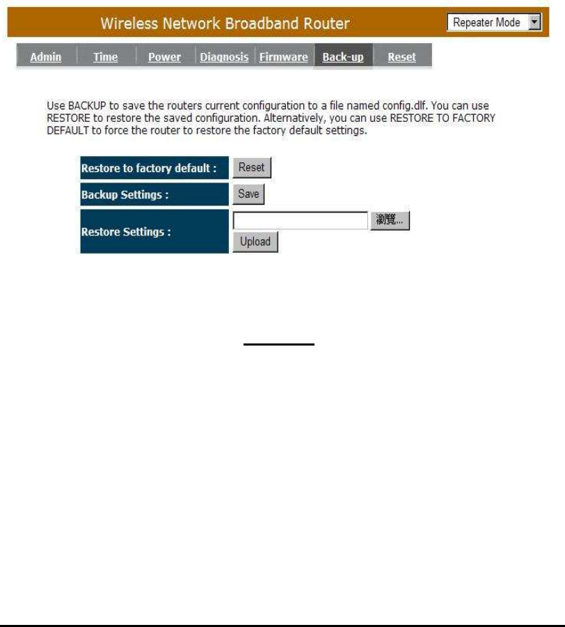
- Back-up
The page allows you to save (Backup) the router’s current configuration
settings. When you save the configuration setting (Backup) you can re-load the
saved configuration into the router through the Restore selection. If extreme
problems occur you can use the Restore to Factory Defaults selection, this will
set all configurations to its original default settings (e.g. when you first purchased
the router).
Backup Settings: This can save the Broadband router current configuration to a
file named "config.bin" on your PC. You can also use the
<Upload> button to restore the saved configuration to the
Broadband router. Alternatively, you can use the "Restore to
Factory Defaults" to force the Broadband router to perform
a power reset and restore the original factory settings.
91
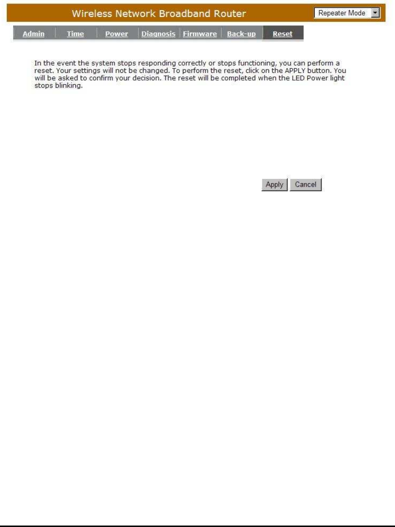
- Reset
You can reset the broadband router when system stops responding correctly
or stop functions.

92
Appendix A – FCC Interference Statement
Federal Communication Commission Interference Statement
This equipment has been tested and found to comply with the limits for a Class B digital device,
pursuant to Part 15 of the FCC Rules. These limits are designed to provide reasonable protection
against harmful interference in a residential installation. This equipment generates, uses and can
radiate radio frequency energy and, if not installed and used in accordance with the instructions,
may cause harmful interference to radio communications. However, there is no guarantee that
interference will not occur in a particular installation. If this equipment does cause harmful
interference to radio or television reception, which can be determined by turning the equipment off
and on, the user is encouraged to try to correct the interference by one of the following measures:
Reorient or relocate the receiving antenna.
Increase the separation between the equipment and receiver.
Connect the equipment into an outlet on a circuit different from that to which the receiver is
connected.
Consult the dealer or an experienced radio/TV technician for help.
This device complies with Part 15 of the FCC Rules. Operation is subject to the following two
conditions: (1) This device may not cause harmful interference, and (2) this device must accept any
interference received, including interference that may cause undesired operation.
FCC Caution: Any changes or modifications not expressly approved by the party responsible for
compliance could void the user's authority to operate this equipment.
IMPORTANT NOTE:
FCC Radiation Exposure Statement:
This equipment complies with FCC radiation exposure limits set forth for an uncontrolled
environment. This equipment should be installed and operated with minimum distance 20cm
between the radiator & your body.
We declare that the product is limited in CH1~CH11 by specified firmware controlled in the USA.
This transmitter must not be co-located or operating in conjunction with any other antenna or
transmitter.

93
Appendix B – IC Interference Statement
Industry Canada statement:
This device complies with RSS-210 of the Industry Canada Rules. Operation is subject to the following
two conditions:
(1) This device may not cause harmful interference, and (2) this device must accept any interference
received, including interference that may cause undesired operation.
IMPORTANT NOTE:
Radiation Exposure Statement:
This equipment complies with IC radiation exposure limits set forth for an uncontrolled environment.
This equipment should be installed and operated with minimum distance 20cm between the radiator &
your body.
This device has been designed to operate with an antenna having a maximum gain of 2 dBi. Antenna
having a higher gain is strictly prohibited per regulations of Industry Canada. The required antenna
impedance is 50 ohms.

94
Appendix C – CE Interference Statement
Europe_ EU Declaration of Conformity
This device complies with the essential requirements of the R&TTE Directive 1999/5/EC. The
following test methods have been applied in order to prove presumption of conformity with
the essential requirements of the R&TTE Directive 1999/5/EC:
- EN60950-1
- Safety of Information Technology Equipment
- EN50385
- Generic standard to demonstrate the compliance of electronic and electrical apparatus
with the basic restrictions related to human exposure to electromagnetic fields (0 Hz -
300 GHz)
- EN 300 328 V1.7.1
- Electromagnetic compatibility and Radio spectrum Matters (ERM); Wideband
Transmission systems; Data transmission equipment operating in the 2,4 GHz ISM band
and using spread spectrum modulation techniques; Harmonized EN covering essential
requirements under article 3.2 of the R&TTE Directive
-
EN 301 489-1 V1.8.1
Electromagnetic compatibility and Radio Spectrum Matters (ERM); ElectroMagnetic
Compatibility (EMC) standard for radio equipment and services; Part 1: Common
technical requirements
- EN 301 489-17 V2.1.1
- Electromagnetic compatibility and Radio spectrum Matters (ERM); ElectroMagnetic
Compatibility (EMC) standard for radio equipment and services; Part 17: Specific
conditions for 2,4 GHz wideband transmission systems and 5 GHz high performance
RLAN equipment
This device is a 2.4 GHz wideband transmission system (transceiver), intended for use in all
EU member states and EFTA countries, except in France and Italy where restrictive use
applies.
In Italy the end-user should apply for a license at the national spectrum authorities in order to
obtain authorization to use the device for setting up outdoor radio links and/or for supplying
public access to telecommunications and/or network services.
This device may not be used for setting up outdoor radio links in France and in some areas
the RF output power may be limited to 10 mW EIRP in the frequency range of 2454 – 2483.5
MHz. For detailed information the end-user should contact the national spectrum authority in
France.
0560

95
Česky
[Czech] [Jméno výrobce] tímto prohlašuje, že tento [typ zařízení] je ve shodě se základními požadavky a
dalšími příslušnými ustanoveními směrnice 1999/5/ES.
Dansk
[Danish] Undertegnede [fabrikantens navn] erklærer herved, at følgende udstyr [udstyrets
typebetegnelse] overholder de væsentlige krav og øvrige relevante krav i direktiv 1999/5/EF.
Deutsch
[German] Hiermit erklärt [Name des Herstellers], dass sich das Gerät [Gerätetyp] in Übereinstimmung mit
den grundlegenden Anforderungen und den übrigen einschlägigen Bestimmungen der Richtlinie
1999/5/EG befindet.
Eesti
[Estonian] Käesolevaga kinnitab [tootja nimi = name of manufacturer] seadme [seadme tüüp = type of
equipment] vastavust direktiivi 1999/5/EÜ põhinõuetele ja nimetatud direktiivist tulenevatele
teistele asjakohastele sätetele.
English Hereby, [name of manufacturer], declares that this [type of equipment] is in compliance with the
essential requirements and other relevant provisions of Directive 1999/5/EC.
Español
[Spanish] Por medio de la presente [nombre del fabricante] declara que el [clase de equipo] cumple con
los requisitos esenciales y cualesquiera otras disposiciones aplicables o exigibles de la
Directiva 1999/5/CE.
Ελληνική
[Greek]
ΜΕ ΤΗΝ ΠΑΡΟΥΣΑ [name of manufacturer] ∆ΗΛΩΝΕΙ ΟΤΙ [type of equipment]
ΣΥΜΜΟΡΦΩΝΕΤΑΙ ΠΡΟΣ ΤΙΣ ΟΥΣΙΩ∆ΕΙΣ ΑΠΑΙΤΗΣΕΙΣ ΚΑΙ ΤΙΣ ΛΟΙΠΕΣ ΣΧΕΤΙΚΕΣ
∆ΙΑΤΑΞΕΙΣ ΤΗΣ Ο∆ΗΓΙΑΣ 1999/5/ΕΚ.
Français
[French] Par la présente [nom du fabricant] déclare que l'appareil [type d'appareil] est conforme aux
exigences essentielles et aux autres dispositions pertinentes de la directive 1999/5/CE.
Italiano
[Italian] Con la presente [nome del costruttore] dichiara che questo [tipo di apparecchio] è conforme ai
requisiti essenziali ed alle altre disposizioni pertinenti stabilite dalla direttiva 1999/5/CE.
Latviski
[Latvian] Ar šo [name of manufacturer / izgatavotāja nosaukums] deklarē, ka [type of equipment /
iekārtas tips] atbilst Direktīvas 1999/5/EK būtiskajām prasībām un citiem ar to saistītajiem
noteikumiem.
Lietuvių
[Lithuanian] Šiuo [manufacturer name] deklaruoja, kad šis [equipment type] atitinka esminius reikalavimus ir
kitas 1999/5/EB Direktyvos nuostatas.
Nederlands
[Dutch] Hierbij verklaart [naam van de fabrikant] dat het toestel [type van toestel] in overeenstemming is
met de essentiële eisen en de andere relevante bepalingen van richtlijn 1999/5/EG.
Malti
[Maltese] Hawnhekk, [isem tal-manifattur], jiddikjara li dan [il-mudel tal-prodott] jikkonforma mal-ħtiġijiet
essenzjali u ma provvedimenti oħrajn relevanti li hemm fid-Dirrettiva 1999/5/EC.
Magyar
[Hungarian] Alulírott, [gyártó neve] nyilatkozom, hogy a [... típus] megfelel a vonatkozó alapvetõ
követelményeknek és az 1999/5/EC irányelv egyéb elõírásainak.
Polski
[Polish] Niniejszym [nazwa producenta] oświadcza, że [nazwa wyrobu] jest zgodny z zasadniczymi
wymogami oraz pozostałymi stosownymi postanowieniami Dyrektywy 1999/5/EC.
Português
[Portuguese] [Nome do fabricante] declara que este [tipo de equipamento] está conforme com os requisitos
essenciais e outras disposições da Directiva 1999/5/CE.
Slovensko
[Slovenian] [Ime proizvajalca] izjavlja, da je ta [tip opreme] v skladu z bistvenimi zahtevami in ostalimi
relevantnimi določili direktive 1999/5/ES.
Slovensky
[Slovak] [Meno výrobcu] týmto vyhlasuje, že [typ zariadenia] spĺňa základné požiadavky a všetky
príslušné ustanovenia Smernice 1999/5/ES.
Suomi
[Finnish] [Valmistaja = manufacturer] vakuuttaa täten että [type of equipment = laitteen tyyppimerkintä]
tyyppinen laite on direktiivin 1999/5/EY oleellisten vaatimusten ja sitä koskevien direktiivin
muiden ehtojen mukainen.
Svenska
[Swedish] Härmed intygar [företag] att denna [utrustningstyp] står I överensstämmelse med de väsentliga
egenskapskrav och övriga relevanta bestämmelser som framgår av direktiv 1999/5/EG.