Senao Networks WBR4200AGN 802.11 abgn Router User Manual ESR750H600H UG
Senao Networks, Inc. 802.11 abgn Router ESR750H600H UG
UserManual.wiki
>
Senao Networks
>
WBR4200AGN User Manual
User Manual
Navigation menu
Upload a User Manual
Namespaces
Wiki Guide
HTML
PDF
Info
Views
User Manual
Discussion / Help
Navigation
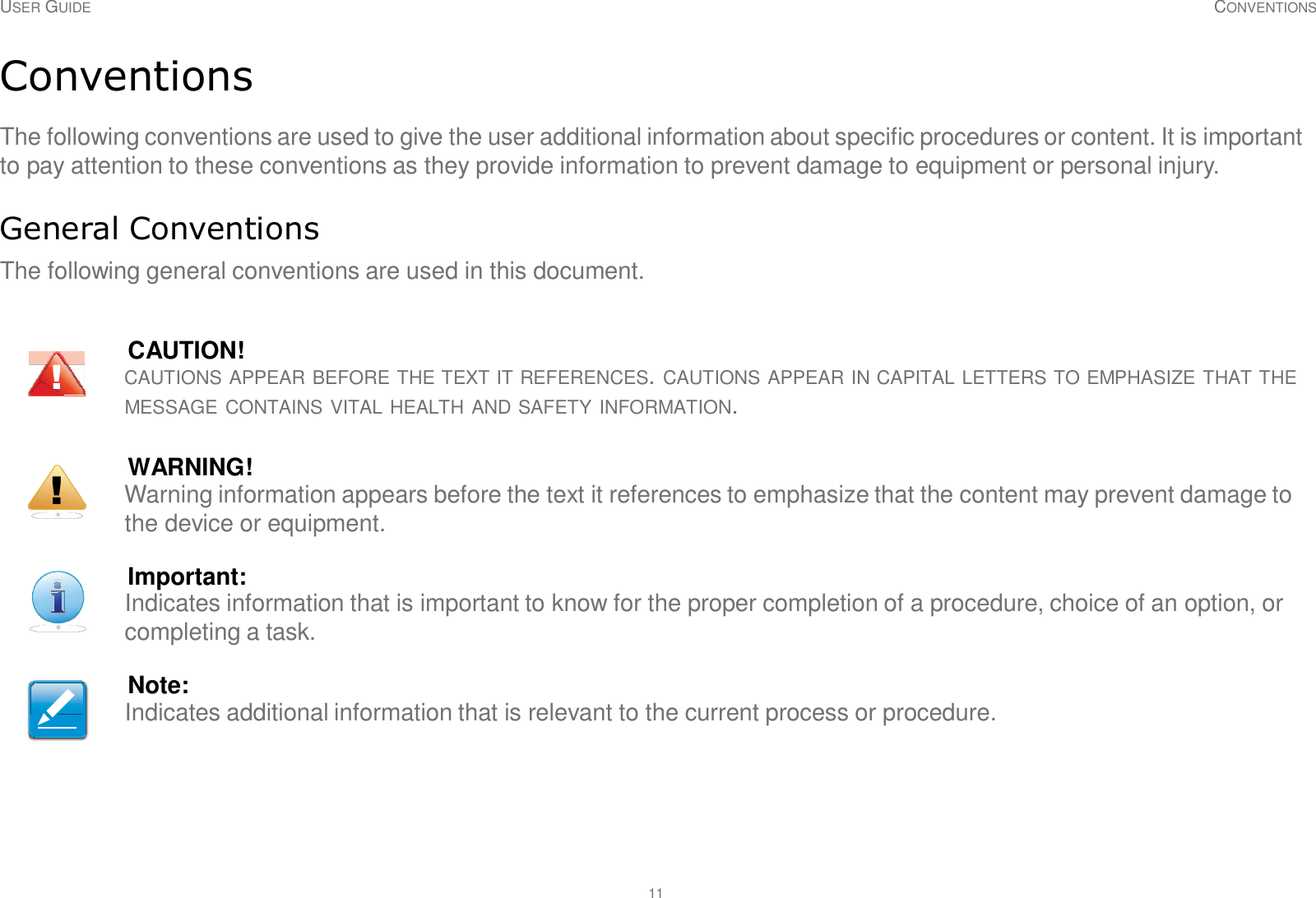


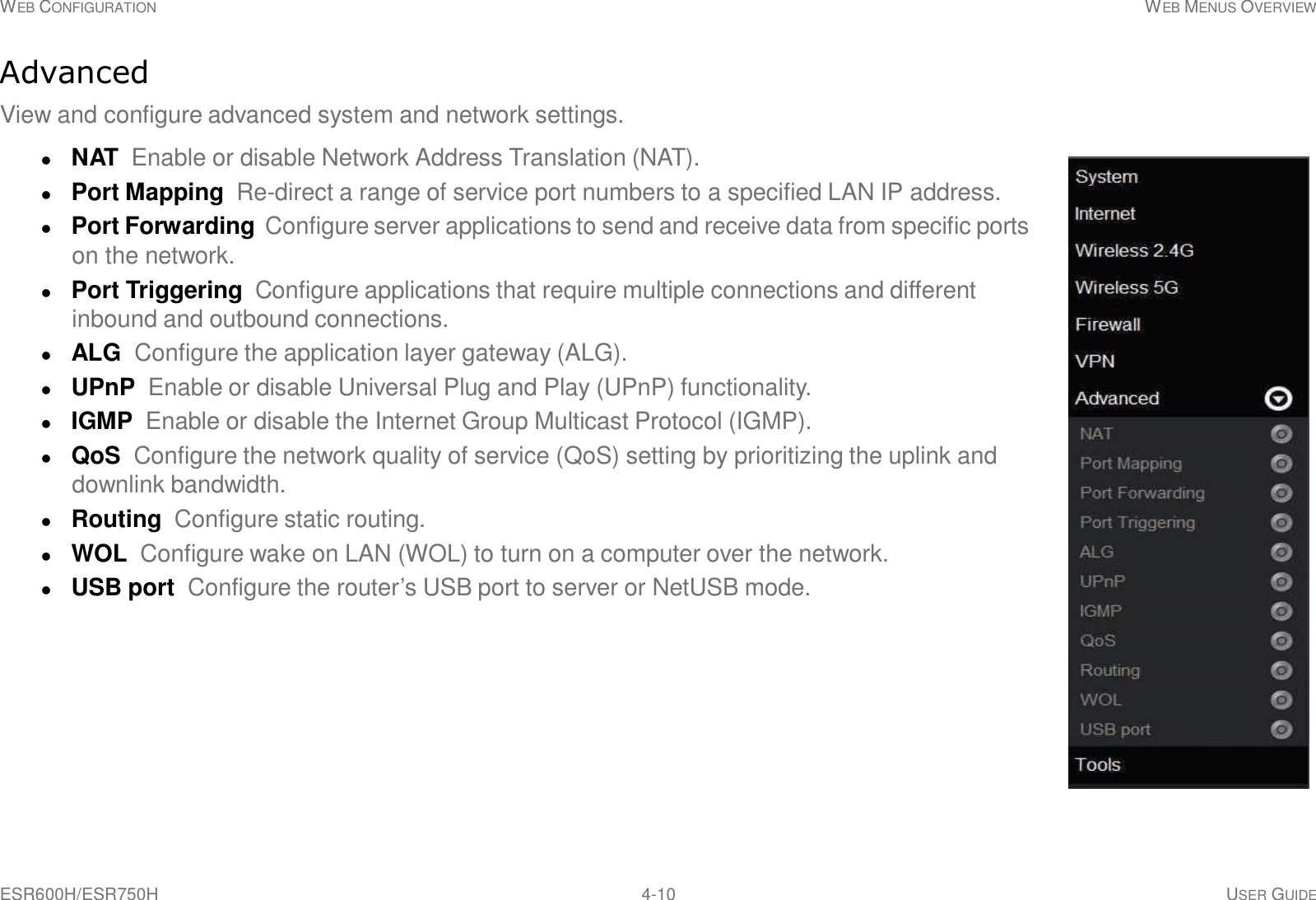

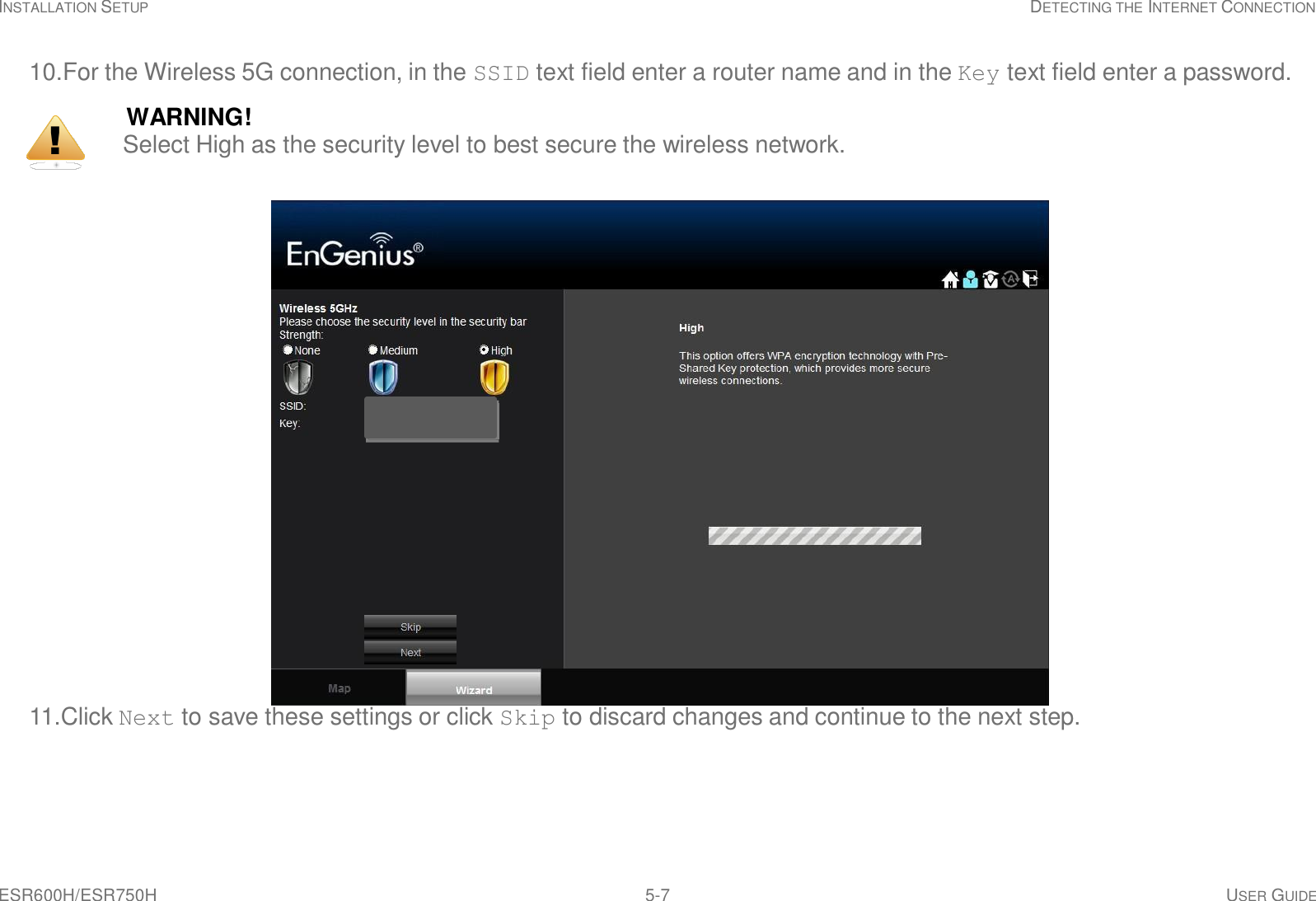
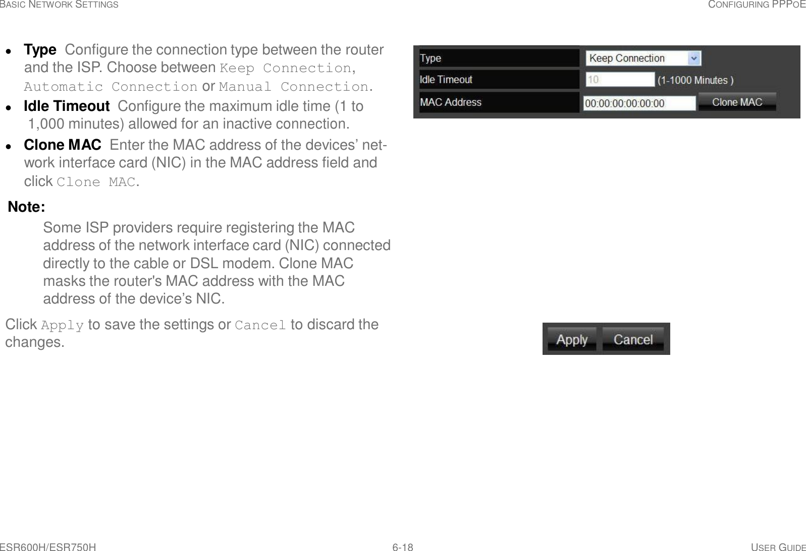


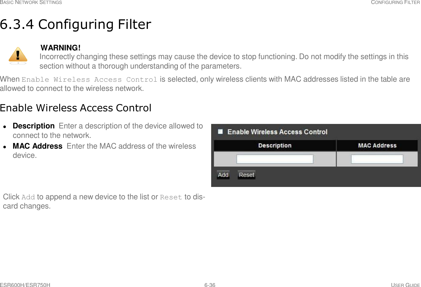
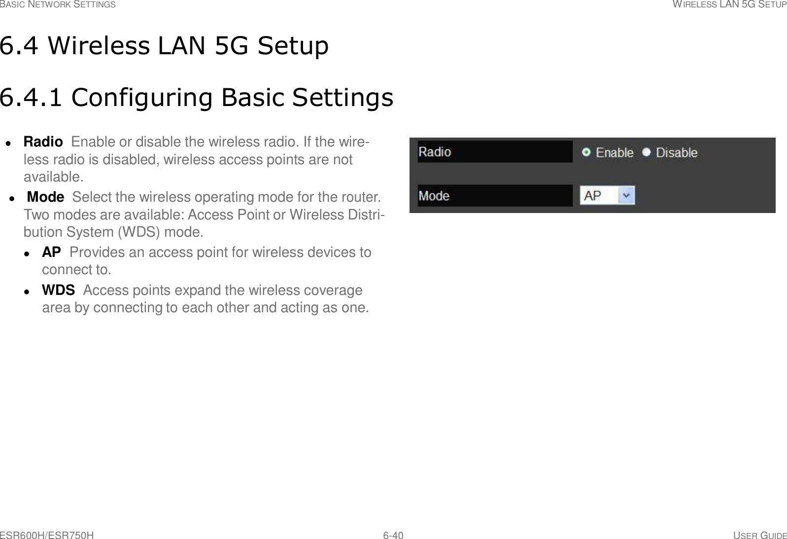
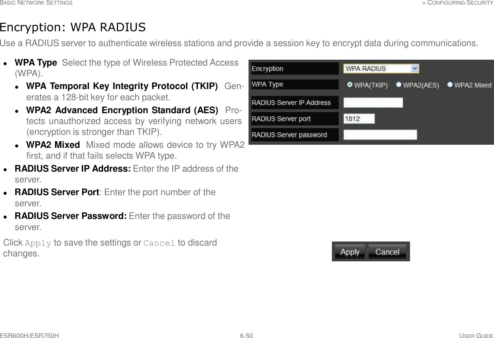
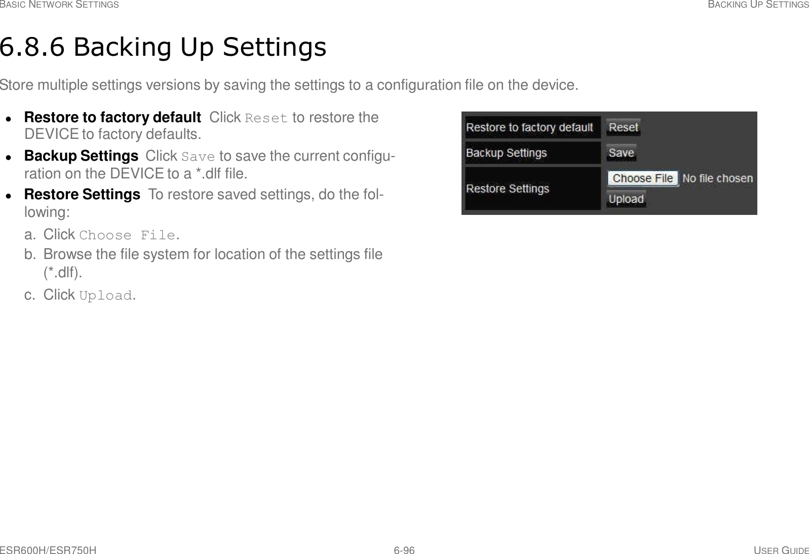
![ESR600H/ESR750H 6-26 USER GUIDE BASIC NETWORK SETTINGS WIRELESS 2.4G LAN SETUP Access Point Mode Configure the wireless settings of the router in access point mode. Band: Select a wireless standard for the network from the following options: 2.4 GHz (B) 2.4 GHz (G) 2.4 GHz (N) 2.4 GHz (B+G) 2.4 GHz (B+G+N) Enable SSID# Select the number of wireless groups, between one and four, available on the network. SSID[#] Enter the name of the wireless network(s). Auto Channel Enable or disable having the router auto- matically select a channel for the wireless network. Auto channel is enabled by default. Select disable to manually assign a specific channel. (Default = Disable) Check Channel Time When auto channel is enabled, select time period that the system checks the appropri- ate channel for the router. Channel When auto channel is disabled, select a channel to assign to the wireless network. Valid value are from one to eleven in the US and one to thirteen in the EU.](https://usermanual.wiki/Senao-Networks/WBR4200AGN/User-Guide-1847283-Page-75.png)
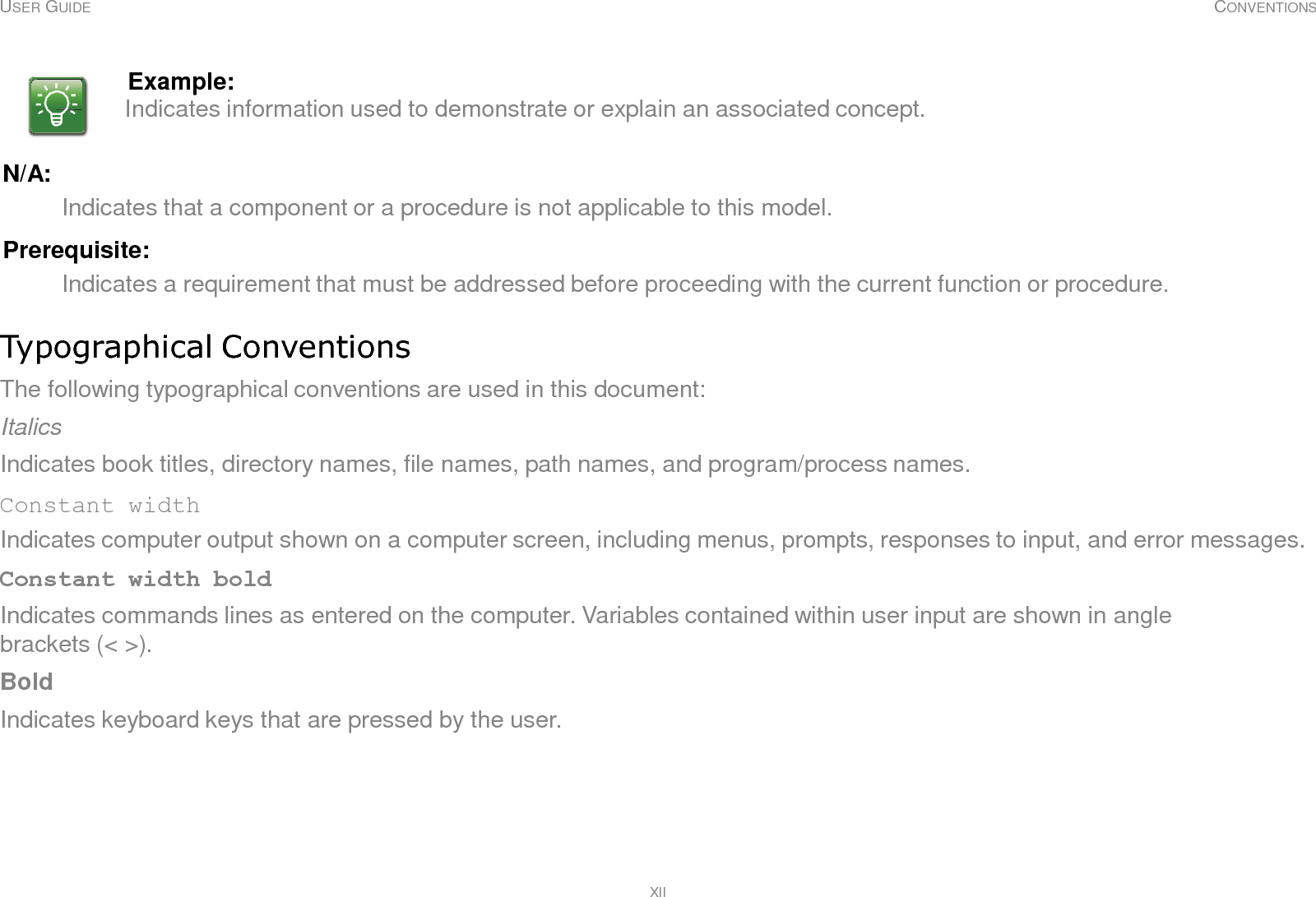
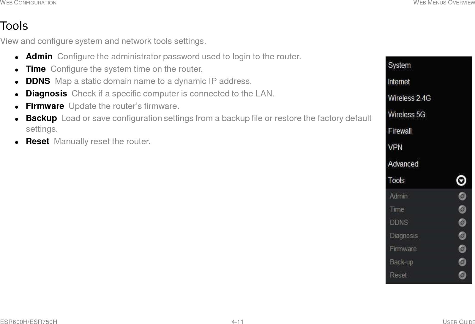
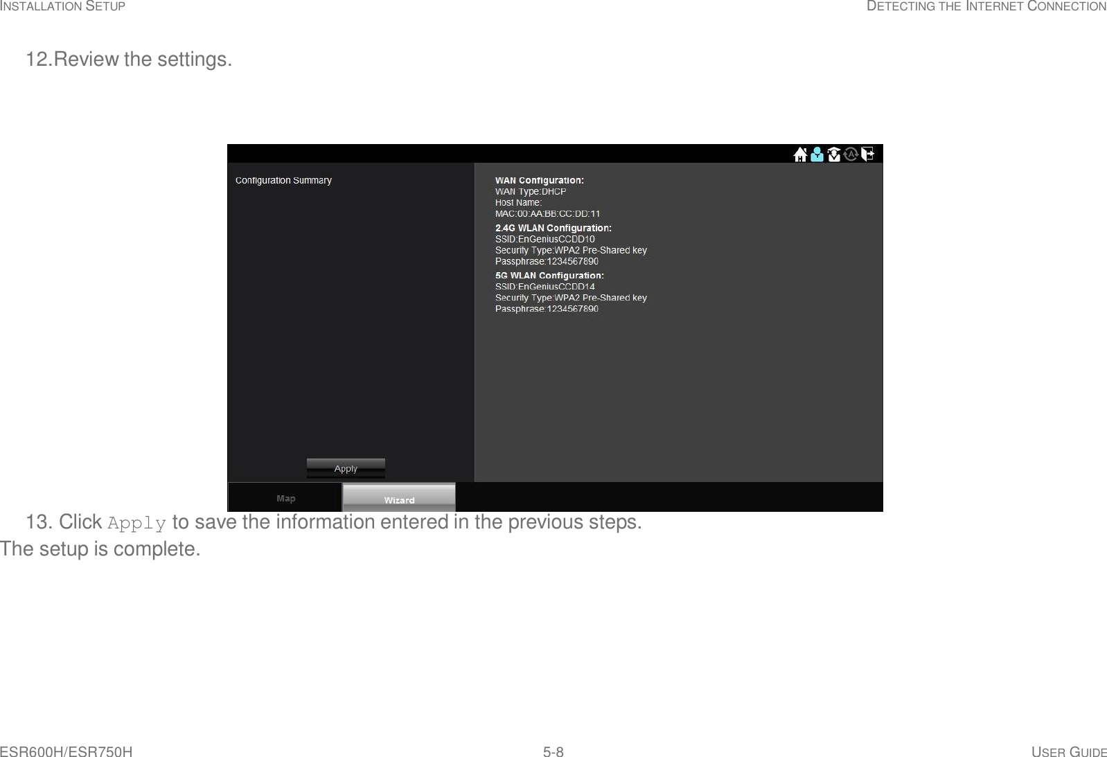
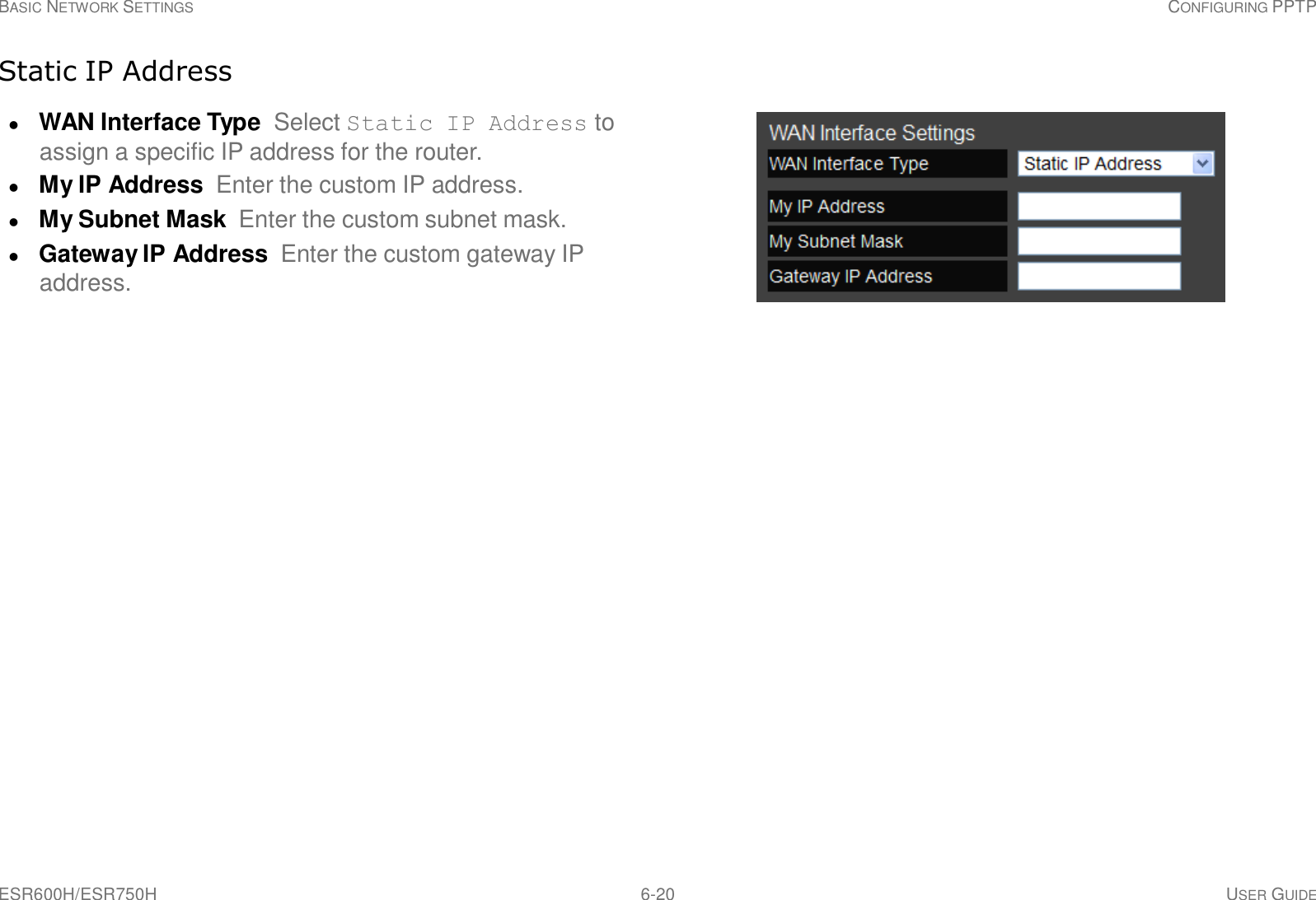
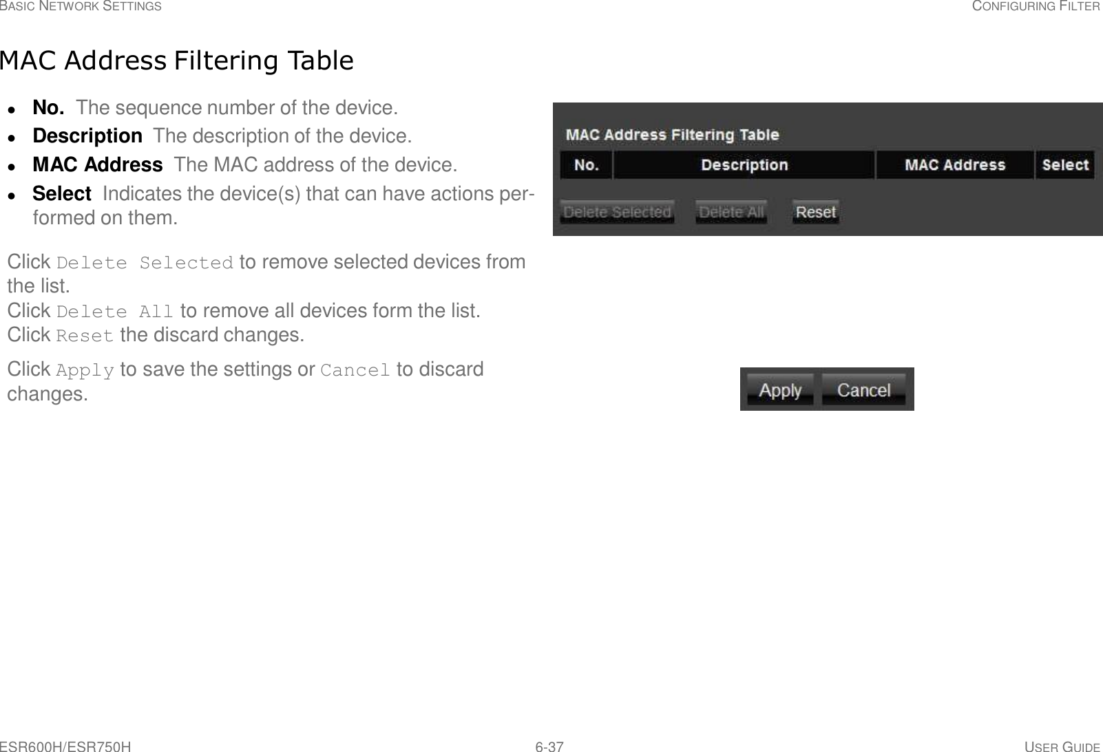
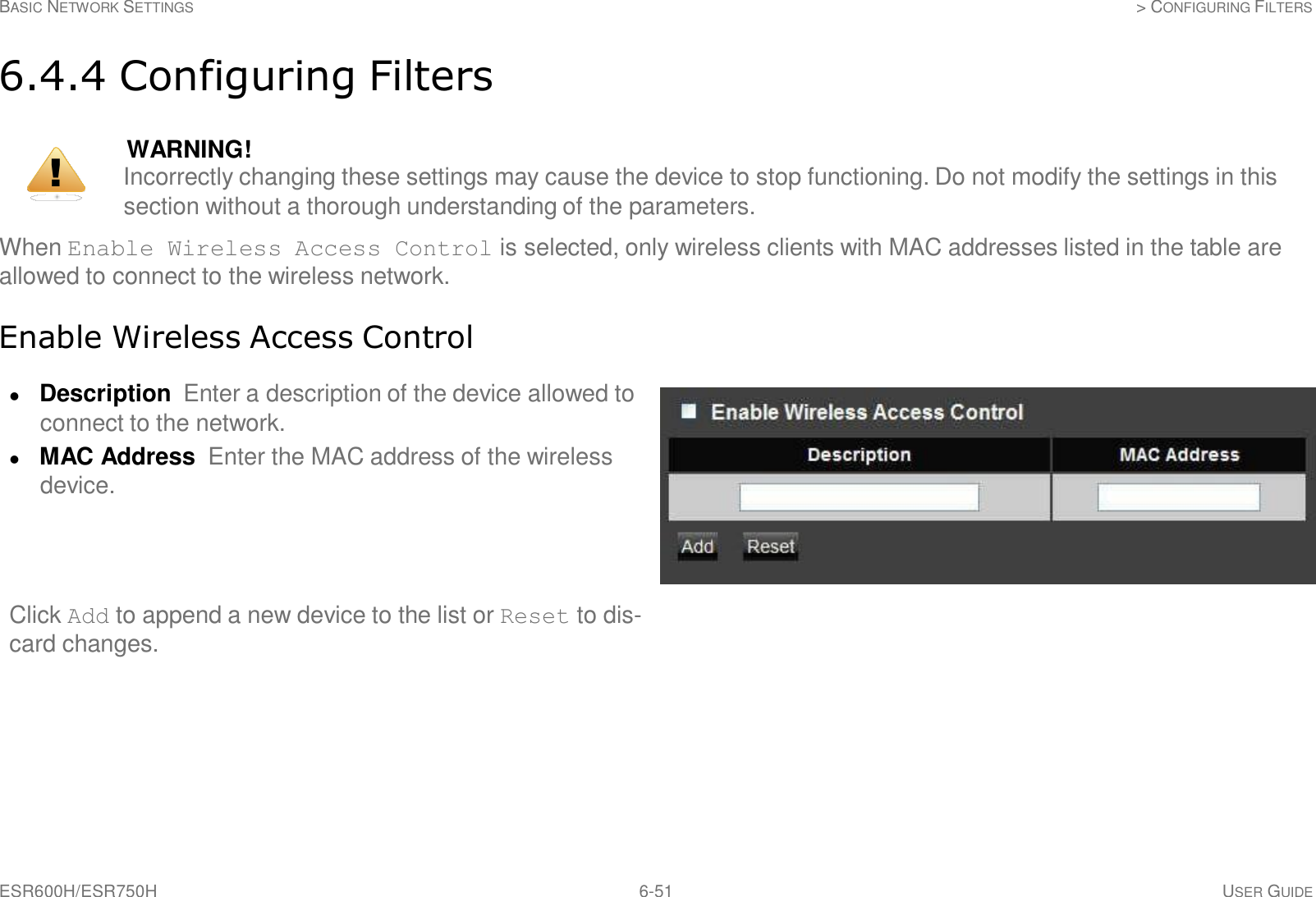
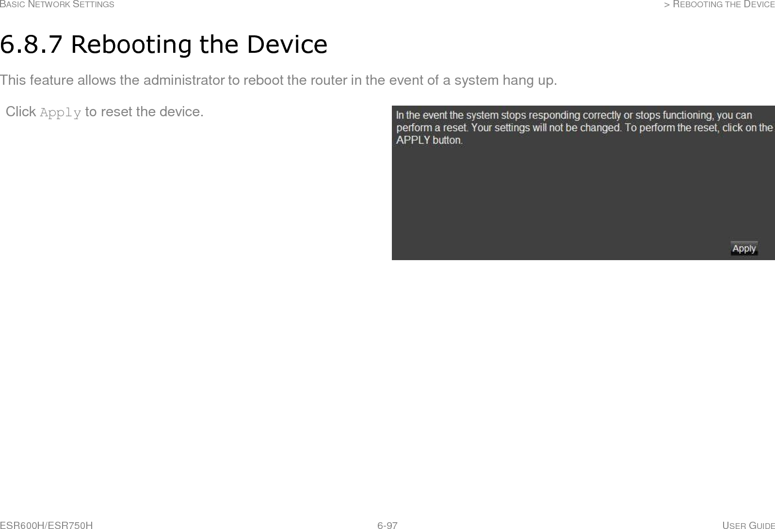
![ESR600H/ESR750H 6-27 USER GUIDE BASIC NETWORK SETTINGS WIRELESS 2.4G LAN SETUP Wireless Distribution System Mode Configure the router’s wireless settings in WDS mode. Channel Select a channel to assign to the wireless net- work. Valid value are from one to eleven in the US and one to thirteen in the EU. MAC Address [#] Enter the MAC address(es) for the wireless access point(s) that are part of the WDS. WDS Data Rate Select the data rate for the WDS. Set Security Click Set Security to display the WDS security settings screen. For security configuration set- tings, refer to “WDS Security Settings Screen” on page 6- 28. Click Apply to save the settings or Cancel to discard changes.](https://usermanual.wiki/Senao-Networks/WBR4200AGN/User-Guide-1847283-Page-76.png)
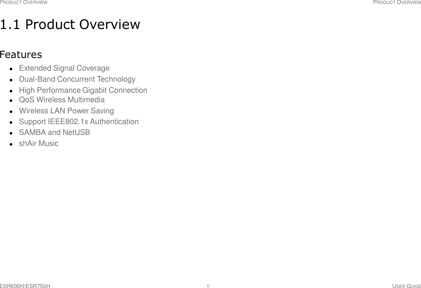
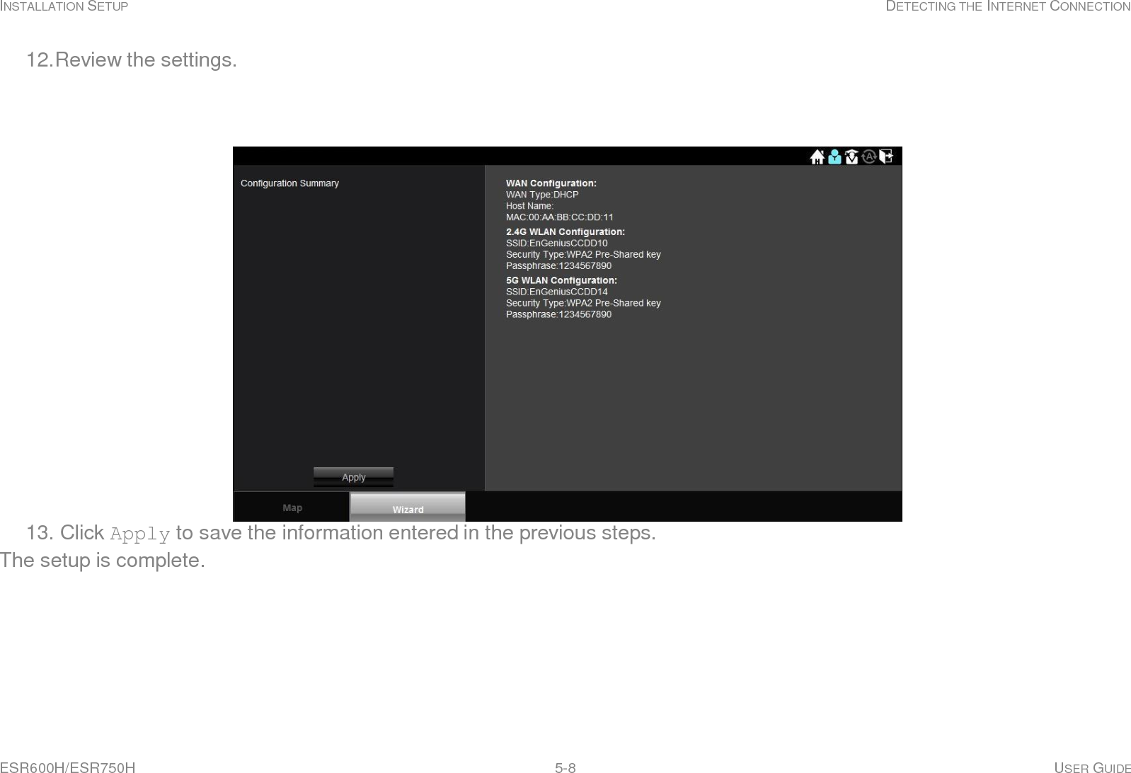
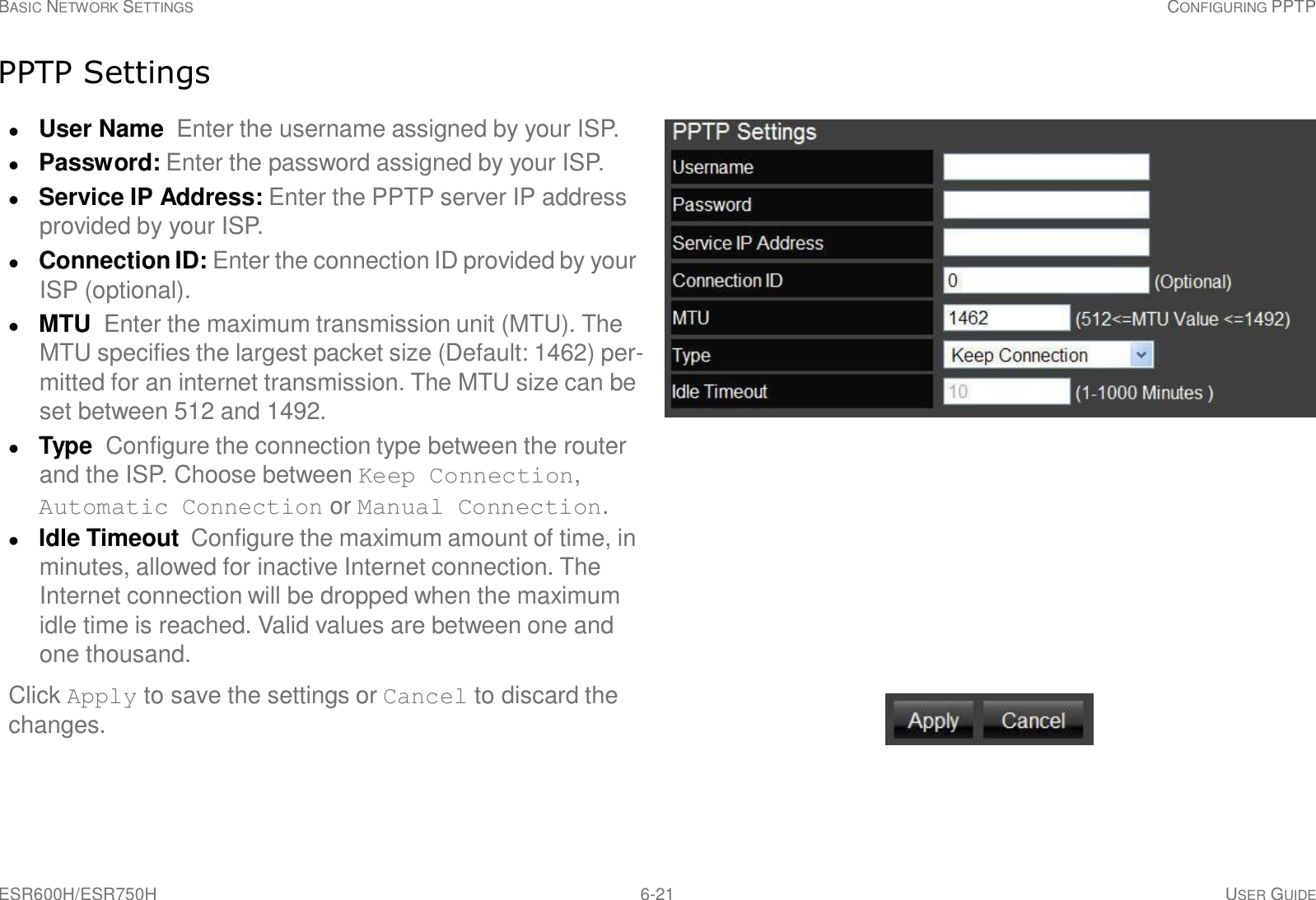
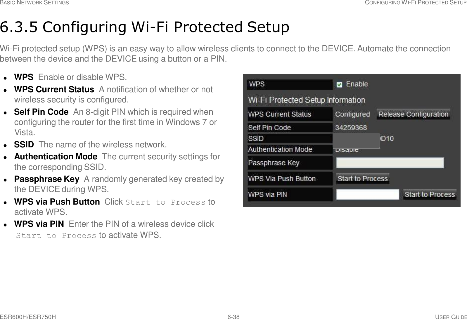
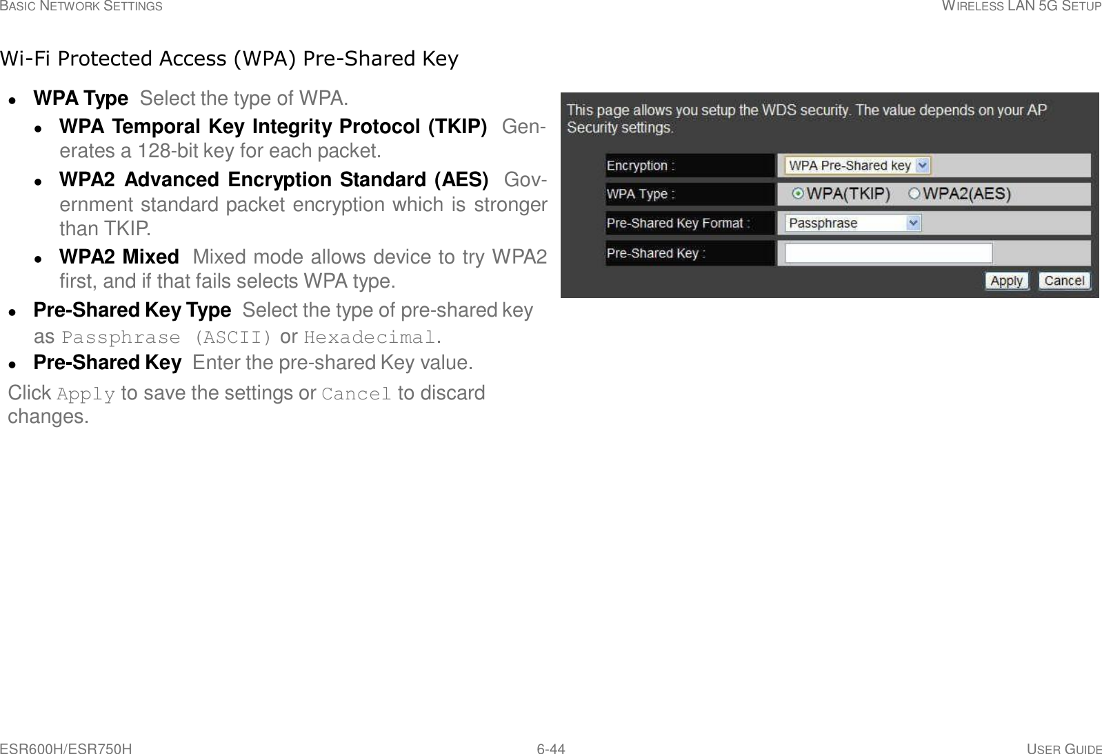
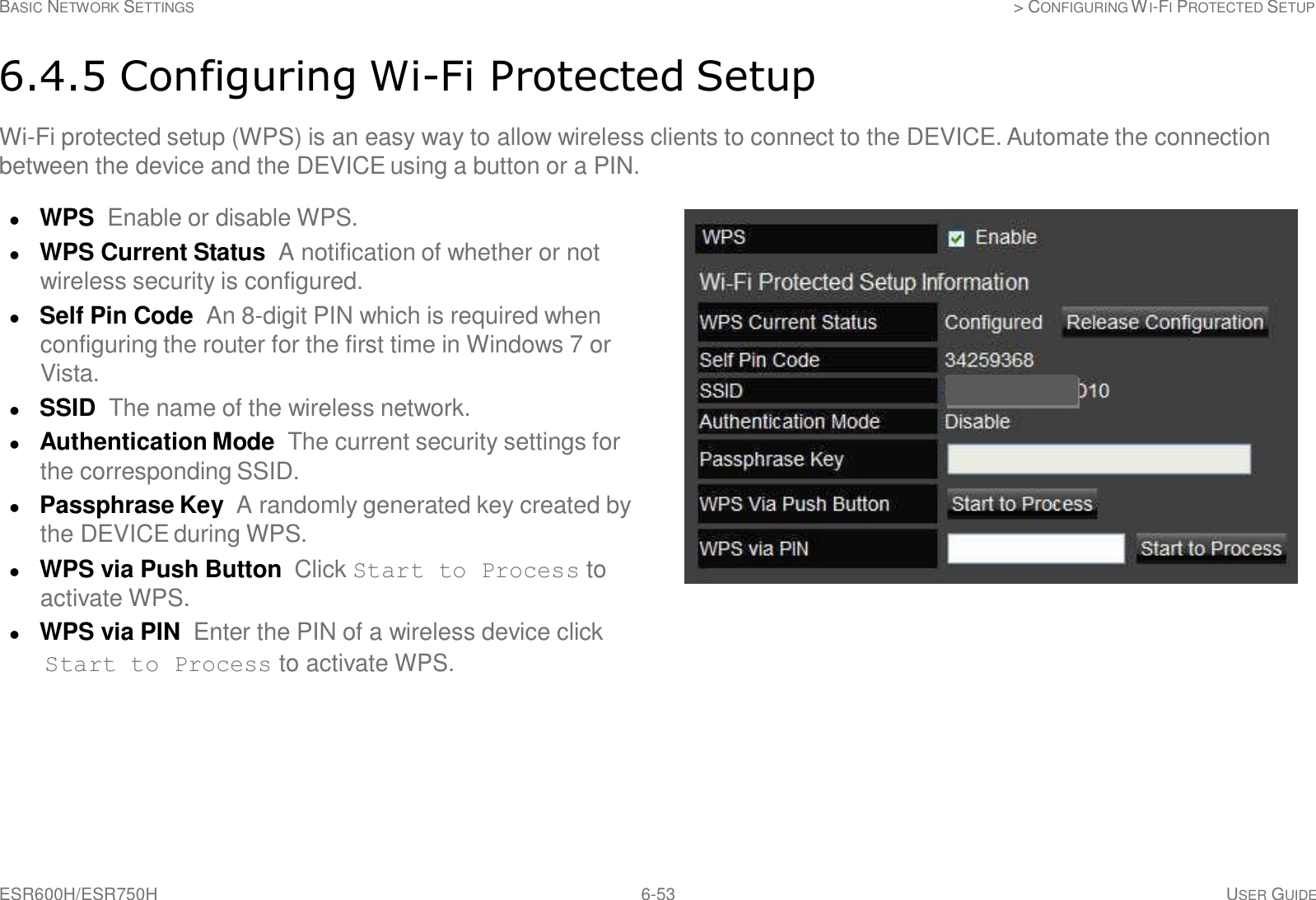
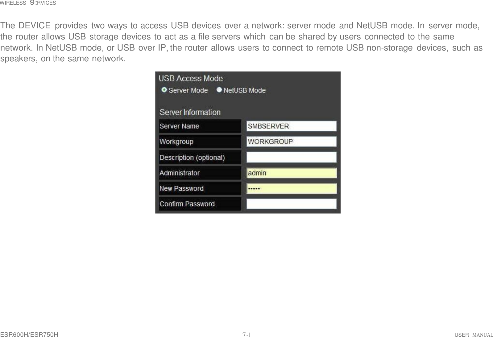
![ESR600H/ESR750H 6-28 USER GUIDE BASIC NETWORK SETTINGS WIRELESS 2.4G LAN SETUP WDS Security Settings Screen Select the type of WDS encryption (Disable, WEP or WPA Pre-Shared Key) for the wireless network. Wired Equivalent Privacy (WEP) Key Length Select between 64-bit and 128-encryption. Key Format Select the type of characters used for the WEP Key: ASCII (5 characters) or Hexadecimal (10 characters). Default Key Select the default encryption key for wire- less transactions. Encryption Key [#] Enter the encryption key(s) used to encrypt the data packets during data transmission. Click Apply to save the settings or Cancel to discard changes.](https://usermanual.wiki/Senao-Networks/WBR4200AGN/User-Guide-1847283-Page-77.png)


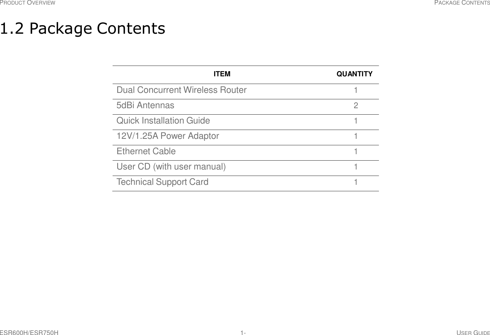
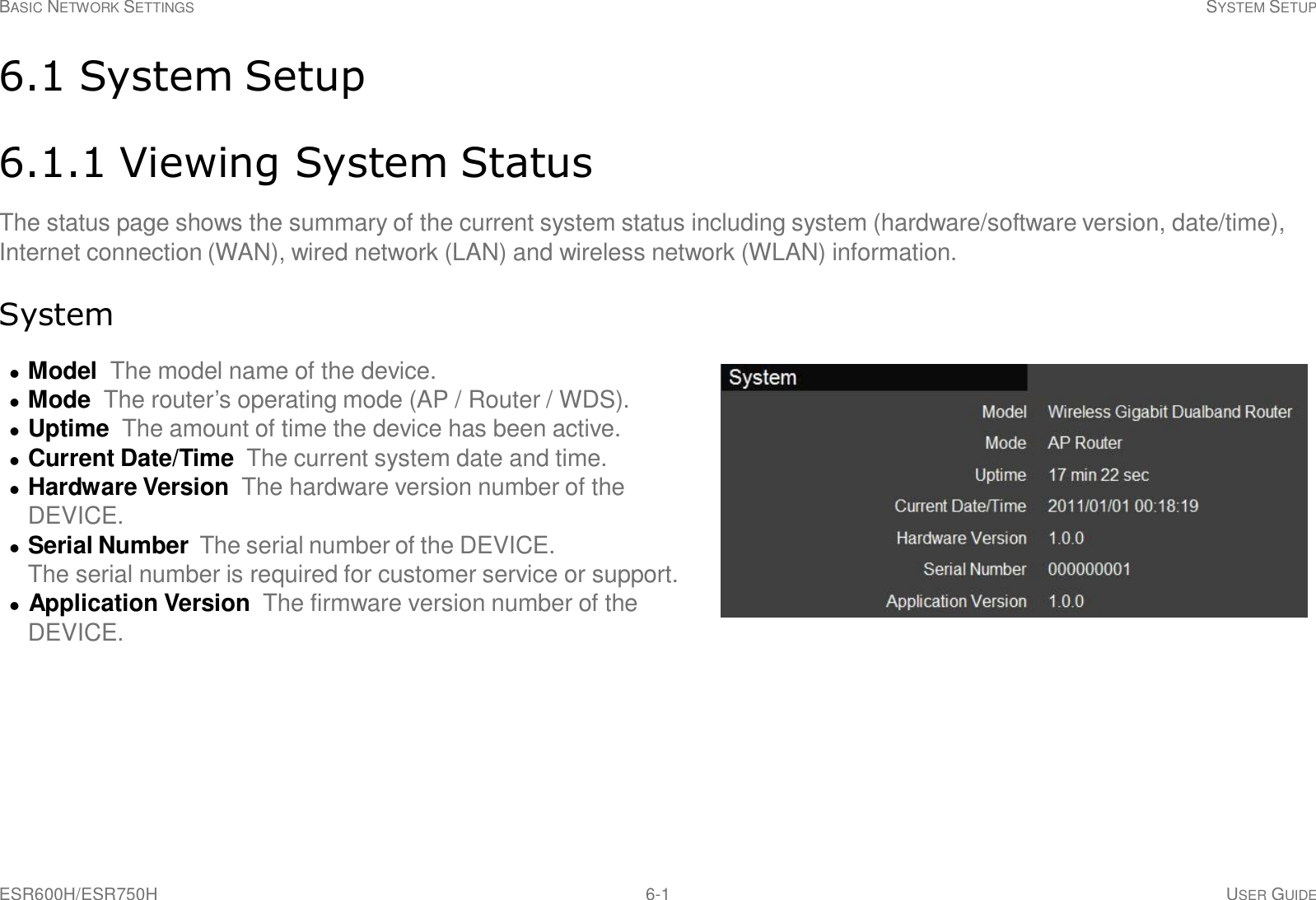
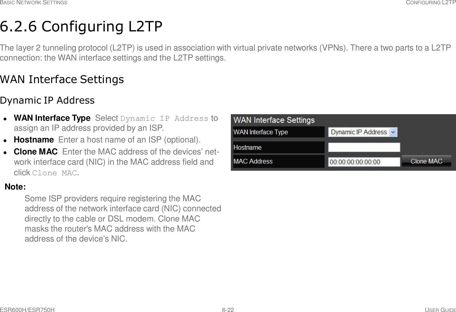
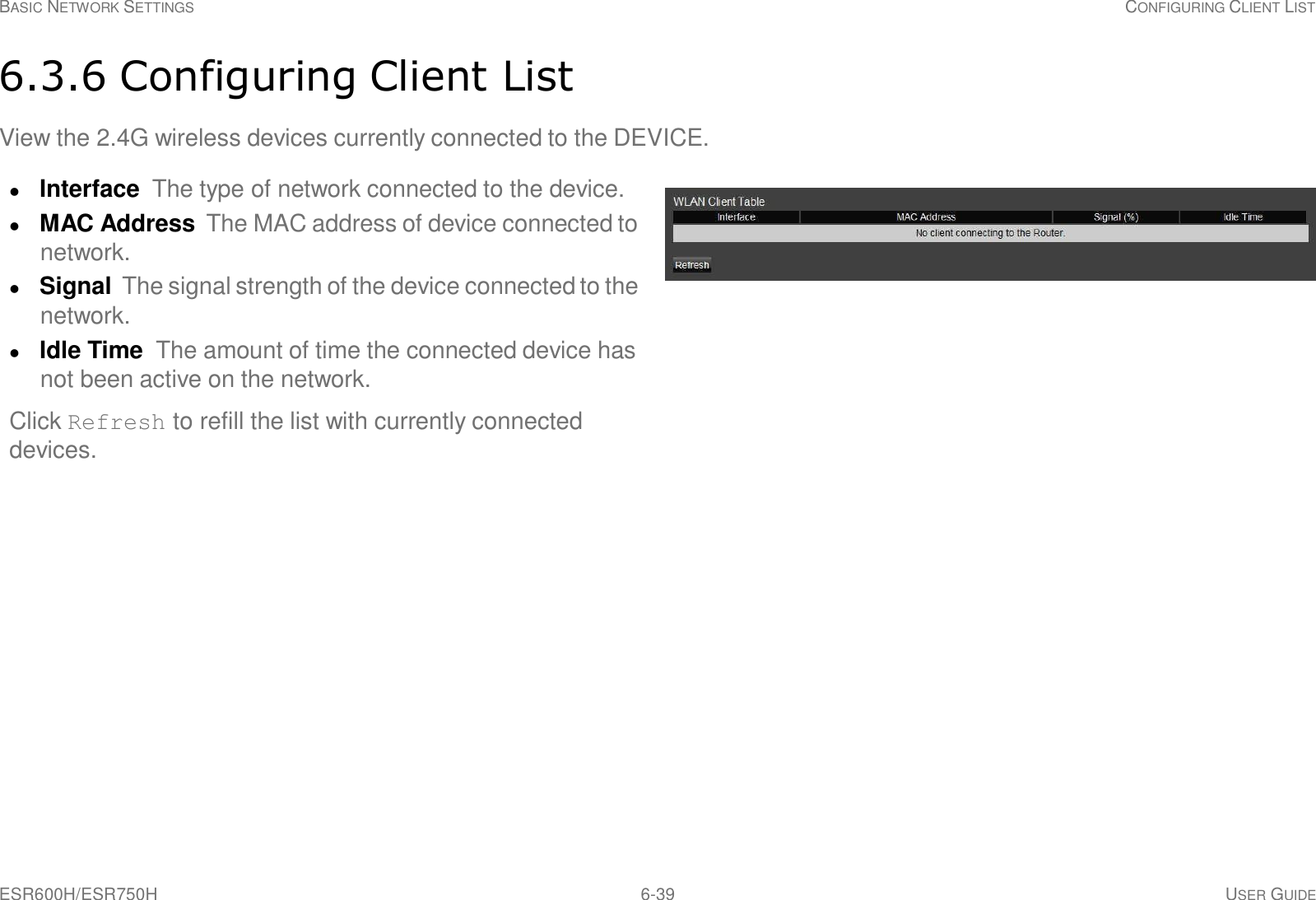
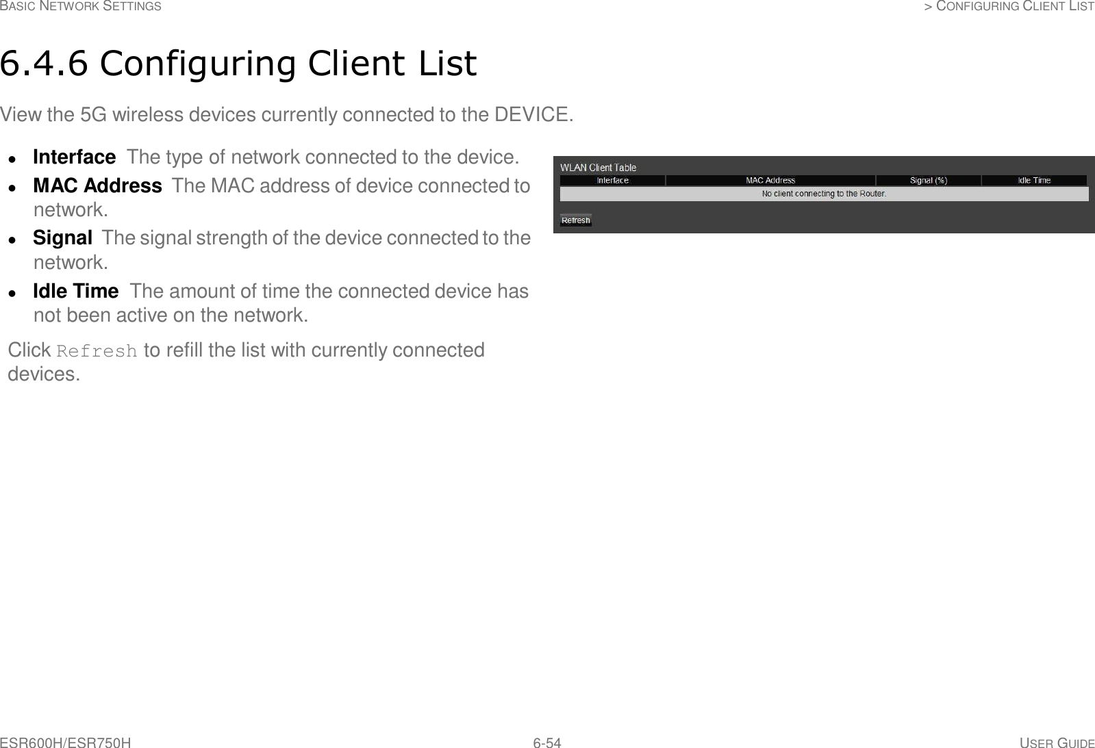
![ESR600H/ESR750H 6-33 USER GUIDE BASIC NETWORK SETTINGS CONFIGURING SECURITY Encryption Type Wired Equivalent Privacy (WEP) Authentication Type Select the type of authentication. Open System Wireless stations can associate with the DEVICE without WEP encryption Shared Key Devices must provide the corresponding WEP key(s) when connecting to the ESR600H/ ESR750H. Auto Key Length Select between 64-bit and 128-encryption. Key Type Select the type of characters used for the WEP Key: ASCII (5 characters) or Hexadecimal (10 characters). Encryption Key [#] Enter the encryption key(s) used to encrypt the data packets during data transmission. Click Apply to save the settings.](https://usermanual.wiki/Senao-Networks/WBR4200AGN/User-Guide-1847283-Page-82.png)

![ESR600H/ESR750H 6-41 USER GUIDE BASIC NETWORK SETTINGS WIRELESS LAN 5G SETUP Access Point Mode Configure the wireless settings of the router in access point mode. Band: Select a wireless standard for the network from the following options: 5 GHz (802.11 a) 5 GHz (802.11 n) 5 GHz (802.11 a/n) Enable SSID# Select the number of wireless groups, between one and four, available on the network. SSID[#] Enter the name of the wireless network(s). Auto Channel Enable or disable having the router auto- matically select a channel for the wireless network. Auto channel is enabled by default. Select disable to manually assign a specific channel. (Default = Disable) Check Channel Time When auto channel is enabled, select time period that the system checks the appropri- ate channel for the router. Channel When auto channel is disabled, select a channel to assign to the wireless network. Wireless Distribution System Mode Configure the wireless settings of the router in WDS mode.](https://usermanual.wiki/Senao-Networks/WBR4200AGN/User-Guide-1847283-Page-90.png)
![ESR600H/ESR750H 6-42 USER GUIDE BASIC NETWORK SETTINGS WIRELESS LAN 5G SETUP Channel Select a channel to assign to the wireless net- work. MAC Address [#] Enter the MAC address(es) for the wireless access point(s) that are part of the WDS. WDS Data Rate Select the data rate for the WDS. Set Security Click Set Security to display the WDS security settings screen. For security configuration set- tings, refer to “WDS Security Settings Screen” on page 6- 43. Click Apply to save the settings or Cancel to discard changes.](https://usermanual.wiki/Senao-Networks/WBR4200AGN/User-Guide-1847283-Page-91.png)
![ESR600H/ESR750H 6-43 USER GUIDE BASIC NETWORK SETTINGS WIRELESS LAN 5G SETUP WDS Security Settings Screen Select the type of WDS encryption (Disable, WEP or WPA Pre-Shared Key) for the wireless network. Wired Equivalent Privacy (WEP) Key Length Select between 64-bit and 128-encryption. Key Format Select the type of characters used for the WEP Key: ASCII (5 characters) or Hexadecimal (10 characters). Default Key Select the default encryption key for wire- less transactions. Encryption Key [#] Enter the encryption key(s) used to encrypt the data packets during data transmission. Click Apply to save the settings or Cancel to discard changes.](https://usermanual.wiki/Senao-Networks/WBR4200AGN/User-Guide-1847283-Page-92.png)

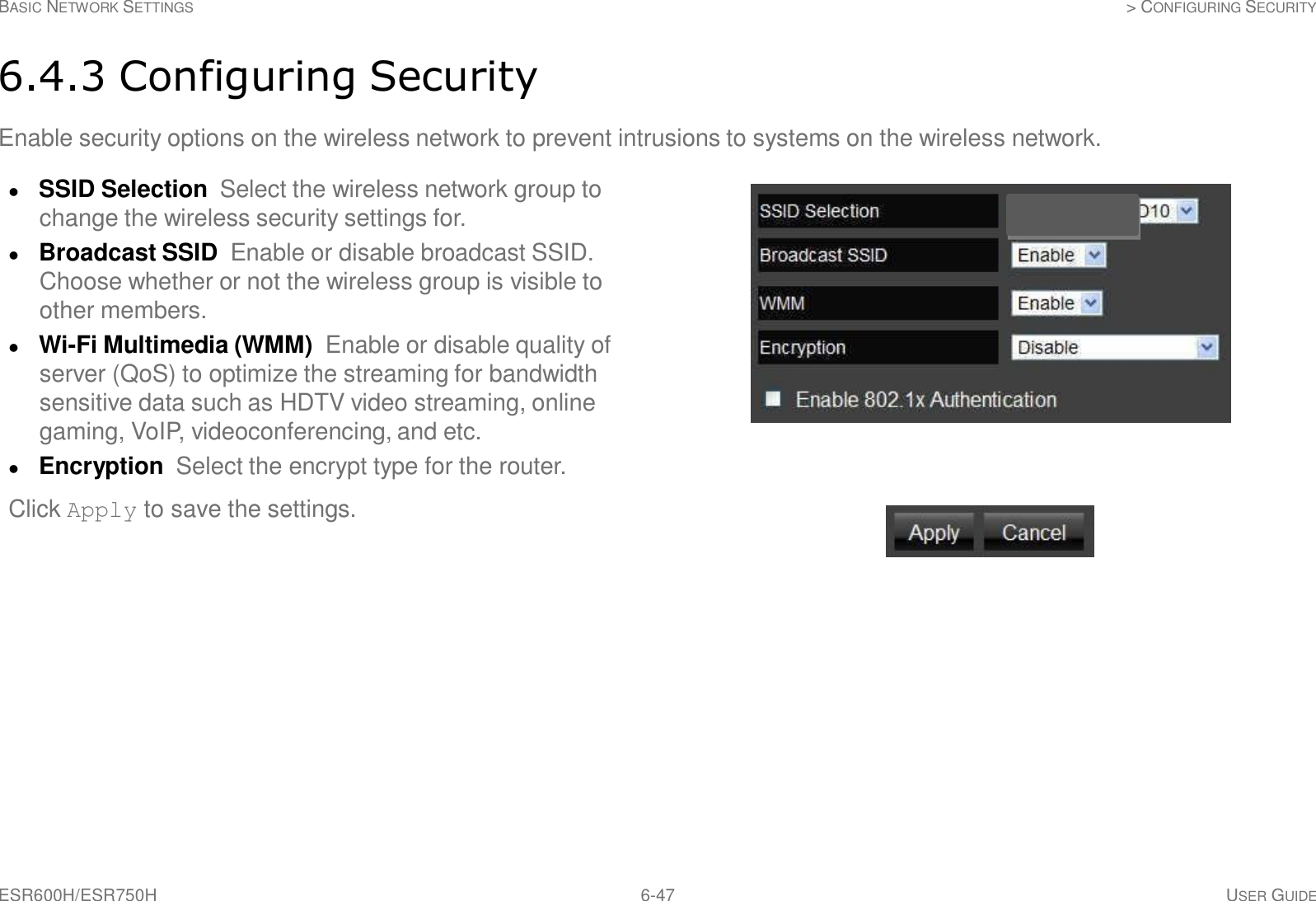
![ESR600H/ESR750H 6-48 USER GUIDE BASIC NETWORK SETTINGS > CONFIGURING SECURITY Encryption Type Wired Equivalent Privacy (WEP) Authentication Type Select the type of authentication. Open System Wireless stations can associate with the DEVICE without WEP encryption Shared Key Devices must provide the corresponding WEP key [up to 4] when connecting to the ESR600H/ ESR750H. Auto The DEVICE automatically gener- ates a passphrase. Key Length Select between 64-bit and 128-encryption. Key Type Select the type of characters used for the WEP Key: ASCII (5 characters) or Hexadecimal (10 characters). Encryption Key [#] Enter the encryption key(s) used to encrypt the data packets during data transmission. Click Apply to save the settings. Note: Do not use WEP type unless your device can not be upgraded to support WPA. Newer encryption types use stronger encryption than WEP.](https://usermanual.wiki/Senao-Networks/WBR4200AGN/User-Guide-1847283-Page-97.png)


![ESR600H/ESR750H 7-7 USER GUIDE WIRELESS SERVICES PRINTER AND SCANNER SI-\A.RING ConnY•Jie Auto-Connect Connec.l Disconnect Request 10 Network Serve!' Printer Cortnect Scanr..er 5. Click Auto Connect Printer. USB Device Server Control Center r;JLQ]L8J System Tools About [3· -x. .±JSet Auro·Connect Pnnter - Delete Auto-Connect Pnnter ........Q Mass Storage·SanDisk Corporation ·Cruzer Contour ...... MFP ·Hewlett·Packard·HP LaserJet 3052 (Manually Connected by TEST]](https://usermanual.wiki/Senao-Networks/WBR4200AGN/User-Guide-1847283-Page-154.png)
![ESR600H/ESR750H 7-9 USER GUIDE WIRELESS 9:RVICES PRINTER AND SCANNER SHARING Co!"!figiJJe Auto·Ccinnect Connect D1soonned Request to Network Server Printer Connect Scanne1 9. The printer is displayed in the list with the label Auto-connected Printer in red. USB Device Server Control Center (Q]l8) System Tools About · ESR-750H ·192.168.1.220 L....... Q Mass Storage ·SanDisk Corporation ·Cruzer Contour '.. ···...MFP ·Hewlett-Packard ·HP LaserJet 3052 Atlto·Connected Pnnte1](https://usermanual.wiki/Senao-Networks/WBR4200AGN/User-Guide-1847283-Page-156.png)