Senao Networks ZF7762 Zone Flex 7762 AccessPoint User Manual Manual
Senao Networks, Inc. Zone Flex 7762 AccessPoint Manual
UserManual.wiki
>
Senao Networks
>
ZF7762 User Manual
Manual
Navigation menu
Upload a User Manual
Namespaces
Wiki Guide
HTML
PDF
Info
Views
User Manual
Discussion / Help
Navigation
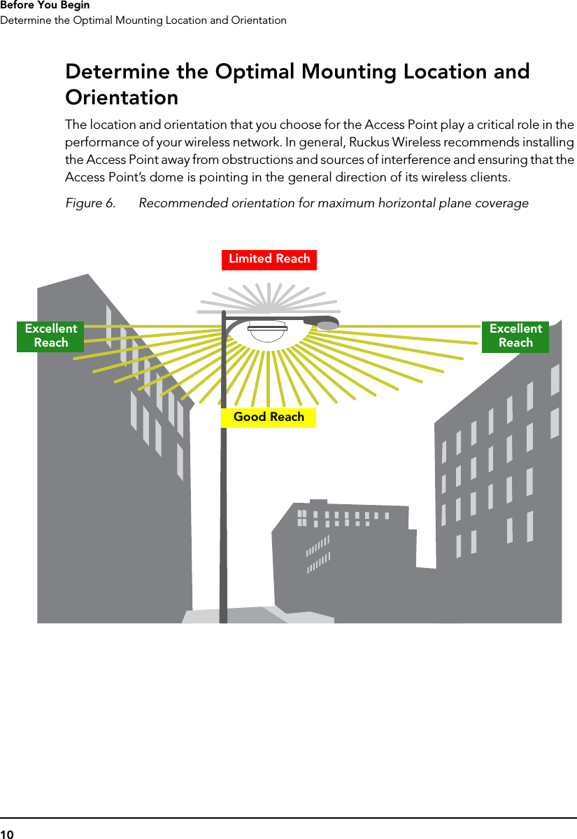
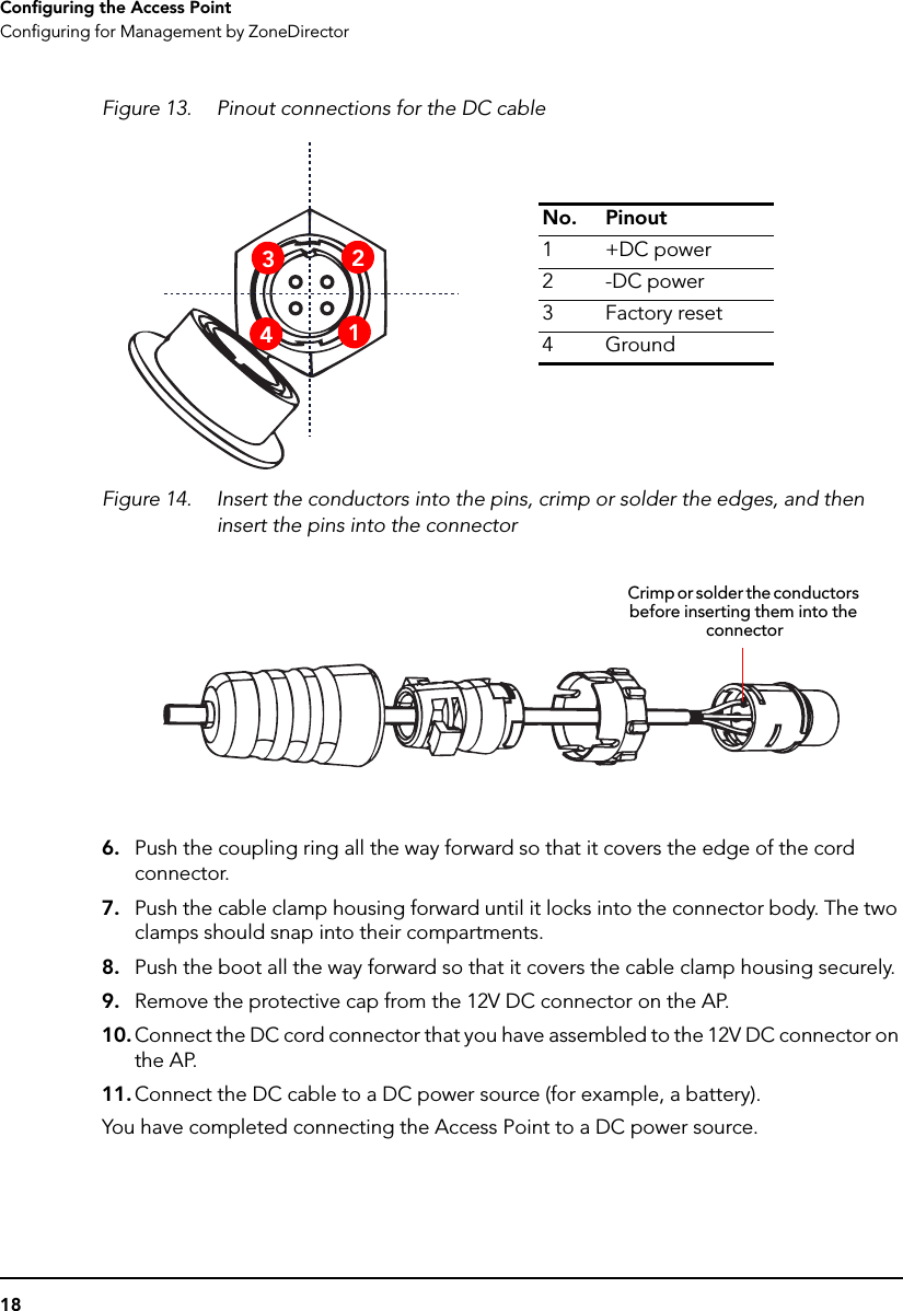
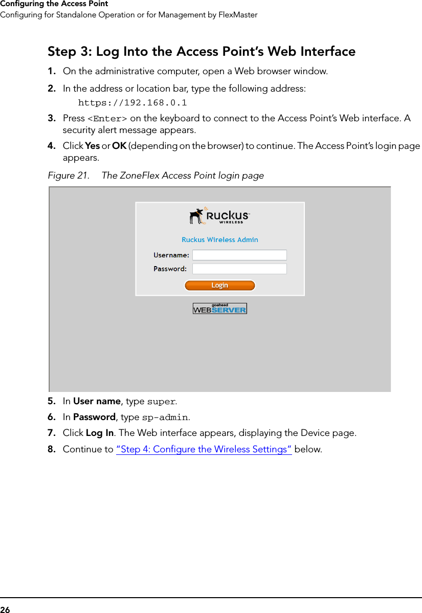
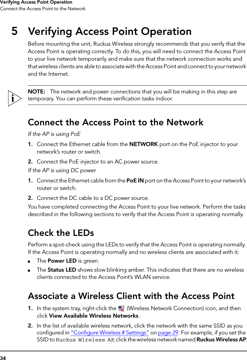
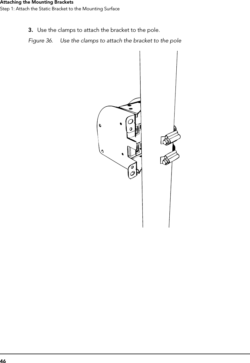
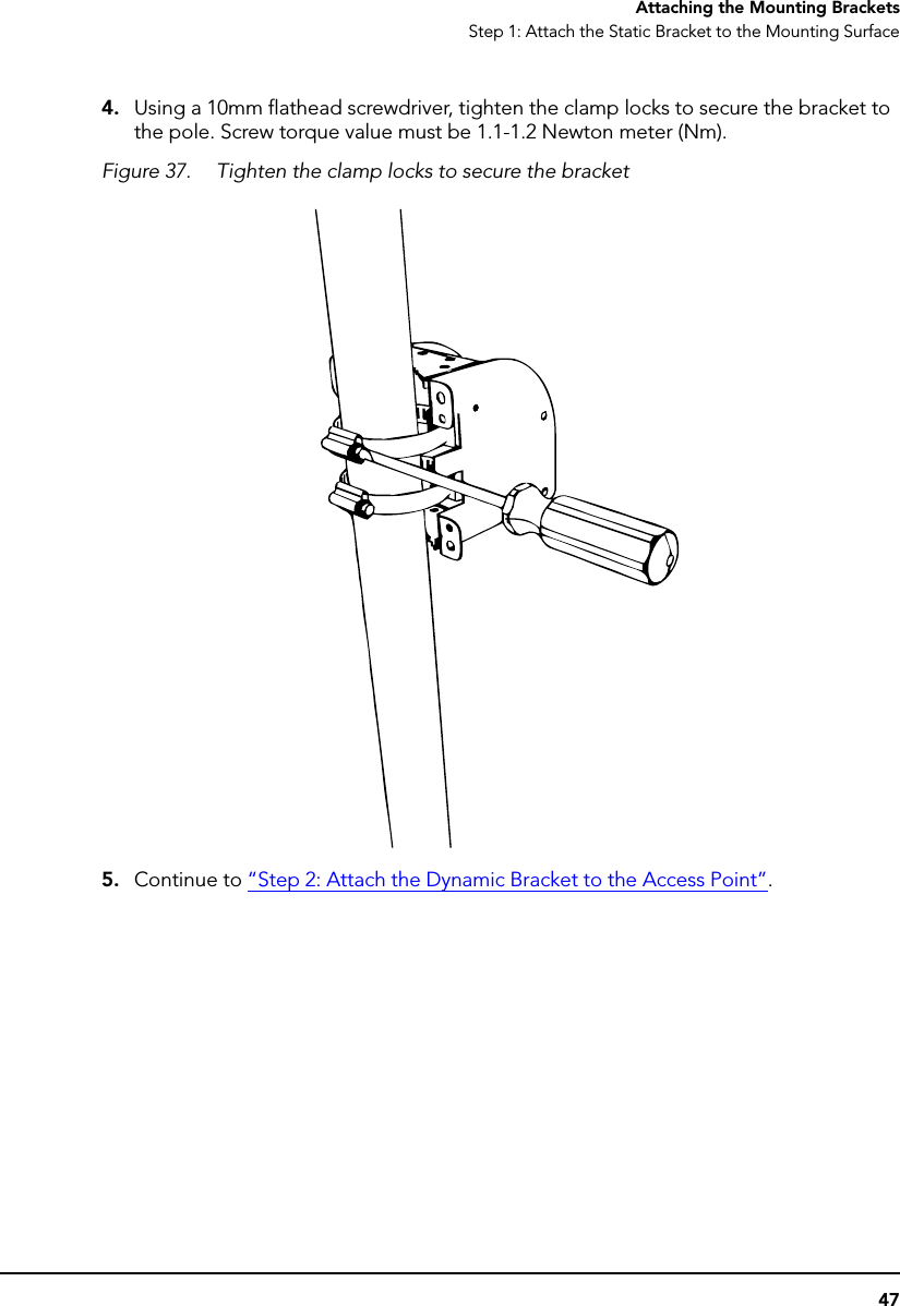
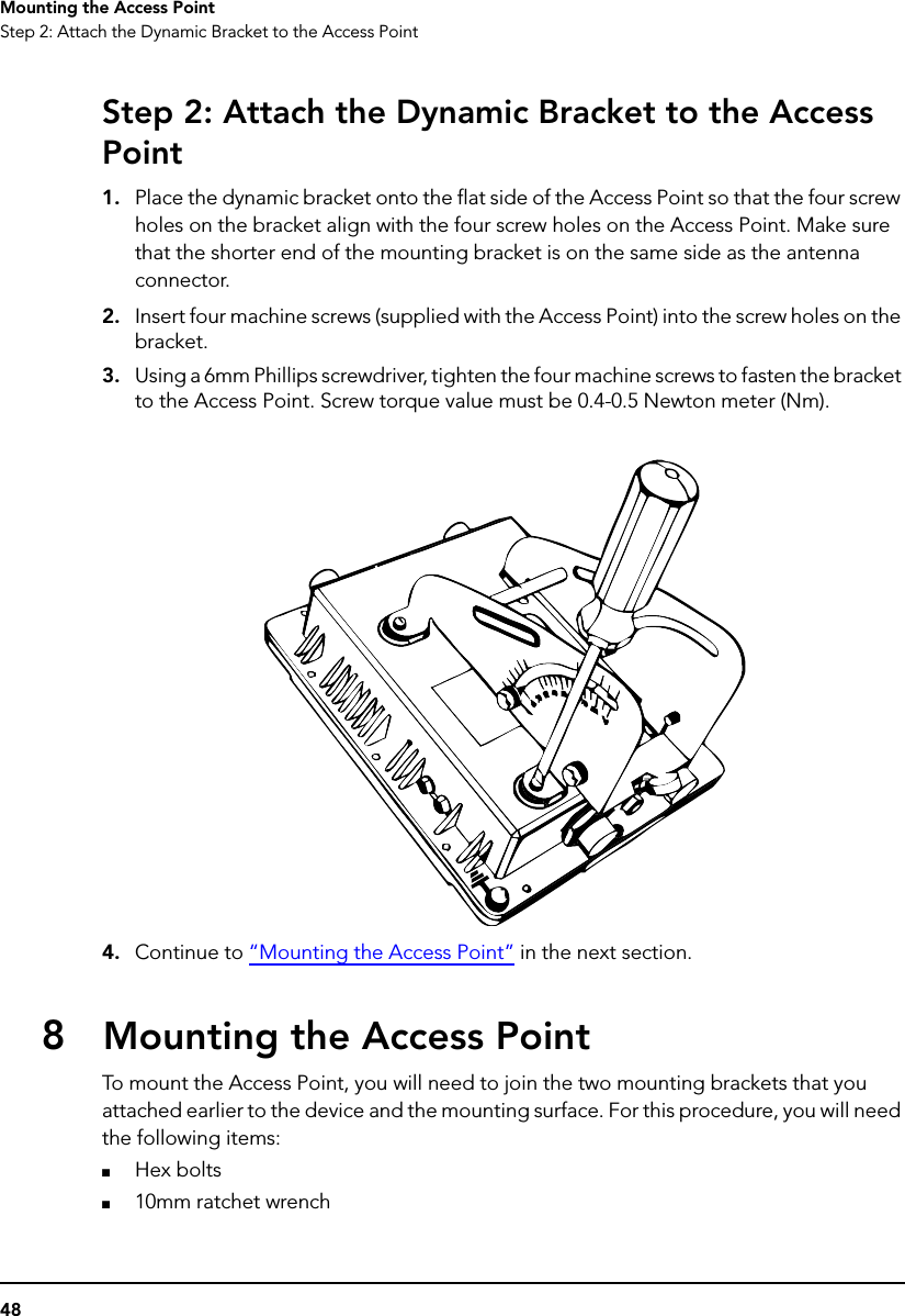
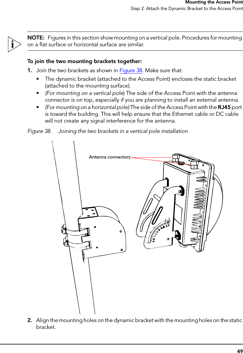

![Professional installation instruction 1. Installation personal: This product is designed for specific application and needs to be installed by a qualified personal who has RF and related rule knowledge. The general user shall not attempt to install or change the setting. 2. Installation location: The product shall be installed at a location where the radiating antenna can be kept 20 cm from nearby person in normal operation condition to meet regulatory RF exposure requirement. 3. External antenna: Use only the antennas which have been approved by Ruckus Wireless. The non-approved antenna(s) may produce unwanted spurious or excessive RF transmitting power which may lead to the violation of FCC limit and is prohibited. 4. Installation procedure: Please refer to user’s manual for the detail. 5. Warning: Please carefully select the installation position and make sure that the final output power does not exceed the limit set force in US Rule CFR 47 part 15 section 6. 15.247 & 15.407. The violation of the rule could lead to serious federal penalty. Federal Communications Commission Notices This product complies with Part 15 of the FCC Rules. Operation is subject to the following two conditions: (1) this device may not cause harmful interference, and (2) this device must accept any interference received, including interference that may cause undesired operation. Radiation Exposure Statement This equipment complies with FCC radiation exposure limits set forth for an uncontrolled environment. This equipment should be installed and operated with minimum distance 20cm between the radiator and your body. This equipment shall not be colocated with any other transmitter. Harmful Interference Notice This product has been tested and complies with the specifications for a Class B digital device, pursuant to Part 15 of the FCC Rules. These limits are designed to provide reasonable protection against harmful interference in a residential installation. This equipment generates, uses, and can radiate radio frequency energy and, if not installed and used according to the instructions, may cause harmful interference to radio communications. However, there is no guarantee that interference will not occur in a particular installation. If this equipment does cause harmful interference to radio or television reception, which is found by turning the equipment off and on, the user is encouraged to try to correct the interference by one or more of the following measures: • Reorient or relocate the receiving antenna • Increase the separation between the equipment or devices • Connect the equipment to an outlet other than the receiver's • Consult a dealer or an experienced radio/TV technician for assistance Changes or modifications to this equipment that have not been approved by Ruckus Wireless may void the user's authority to operate this equipment. For operation within 5.15 ~ 5.25GHz frequency range, it is restricted to indoor environment. External Antenna This device has been designed to operate with a patch antenna, and having a maximum gain of 14 dBi. Other antennatypes or having a gain greater than 14 dBi are strictly prohibited for use with this device. The required antenna impedance is 50 ohms. Industry Canada Statement This device complies with Industry Canada ICES-003 and RSS210 rules. Operation is subject to the following two conditions: 1. This device may not cause interference and 2. This device must accept any interference, including interference that may cause undesired operation of the device. Cet appareil est conforme aux normes NMB003 et RSS210 d'Industrie Canada. Le fonctionnement est soumis aux conditions suivantes : 1. Ce périphérique ne doit pas causer d'interférences; 2. Ce périphérique doit accepter toutes les interférences reçues, y compris celles qui risquent d'entraîner un fonctionnement indésirable. This equipment complies with IC radiation exposure limits set forth for an uncontrolled environment. This equipment should be installed and operated with minimum distance 20cm between the radiator & your body. Caution: The device for the band 5150-5250 MHz is only for indoor usage to reduce potential for harmful interference to co-channel mobile satellite systems. High power radars are allocated as primary users (meaning they have priority) of 5250-5350 MHz and 5650-5850 MHz and these radars could cause interference and/or damage to LE-LAN devices. This device has been designed to operate with an antenna having a maximum gain of 14 dBm. Antenna having a higher gain is strictly prohibited per regulations of Industry Canada. The required antenna impedance is 50 ohms. Australia Statement This device complies with the ACMA requirements for a Wi-Fi device namely Radio Communications (Low Impact Potential Devices) Class Licence 2000 Amd. 1:2007 and Radiocommunications (Compliance Labelling – Electromagnetic Radiation) Notice 2003. The equipment complies with the ACMA requirements for radiation exposure for a "general user/non-aware user". This equipment should be installed and operated with a minimum distance of 20 cm between the radiator and your body. This equipment complies with the Australian safety requirements. European Union Notices This product only supplied by Limited Power sources (sub-clause 2.5 of standard EN 60950-1 Compliance Information for 2.4-GHz Wireless Products The following standards were applied during the assessment of the product against the requirements of the Directive 1999/5/EC: • Radio: EN 300 328, EN 301 893 • EMC: EN 301 489-1, EN 301 489-17 • Safety: EN 60950, EN 50385 The frequency band 5150 – 5350 MHz is restricted to indoor use. National Restrictions This product may be used in all EU countries (and other countries following the EU directive 1999/5/EC) without any limitation except for the countries mentioned below: Ce produit peut être utilisé dans tous les pays de l’UE (et dans tous les pays ayant transposés la directive 1999/5/CE) sans aucune limitation, excepté pour les pays mentionnés ci-dessous: Questo prodotto è utilizzabile in tutte i paesi EU (ed in tutti gli altri paesi che seguono le direttive EU 1999/5/EC) senza nessuna limitazione, eccetto per i paesii menzionati di seguito: Das Produkt kann in allen EU Staaten ohne Einschränkungen eingesetzt werden (sowie in anderen Staaten die der EU Direktive 1999/5/CE folgen) mit Außnahme der folgenden aufgeführten Staaten: France In case the product is used outdoors, the output power is restricted in some parts of the band. See the table below or check http://www.arcep.fr/ for more details. Dans la cas d’une utilisation en extérieur, la puissance de sortie est limitée pour certaines parties de la bande. Reportezvous à la table 1 ou visitez http://www.arcep.fr/ pour de plus amples détails. Location Frequency Range (MHz) Power (EIRP) Indoor (No restrictions) 2400-2483.5 100 mW (20 dBm) Outdoor 2400-2454 [2454-2483.5] 100 mW (20 dBm) [10 mW(10 dBm)]](https://usermanual.wiki/Senao-Networks/ZF7762/User-Guide-1158109-Page-61.png)
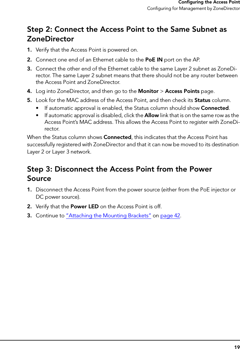
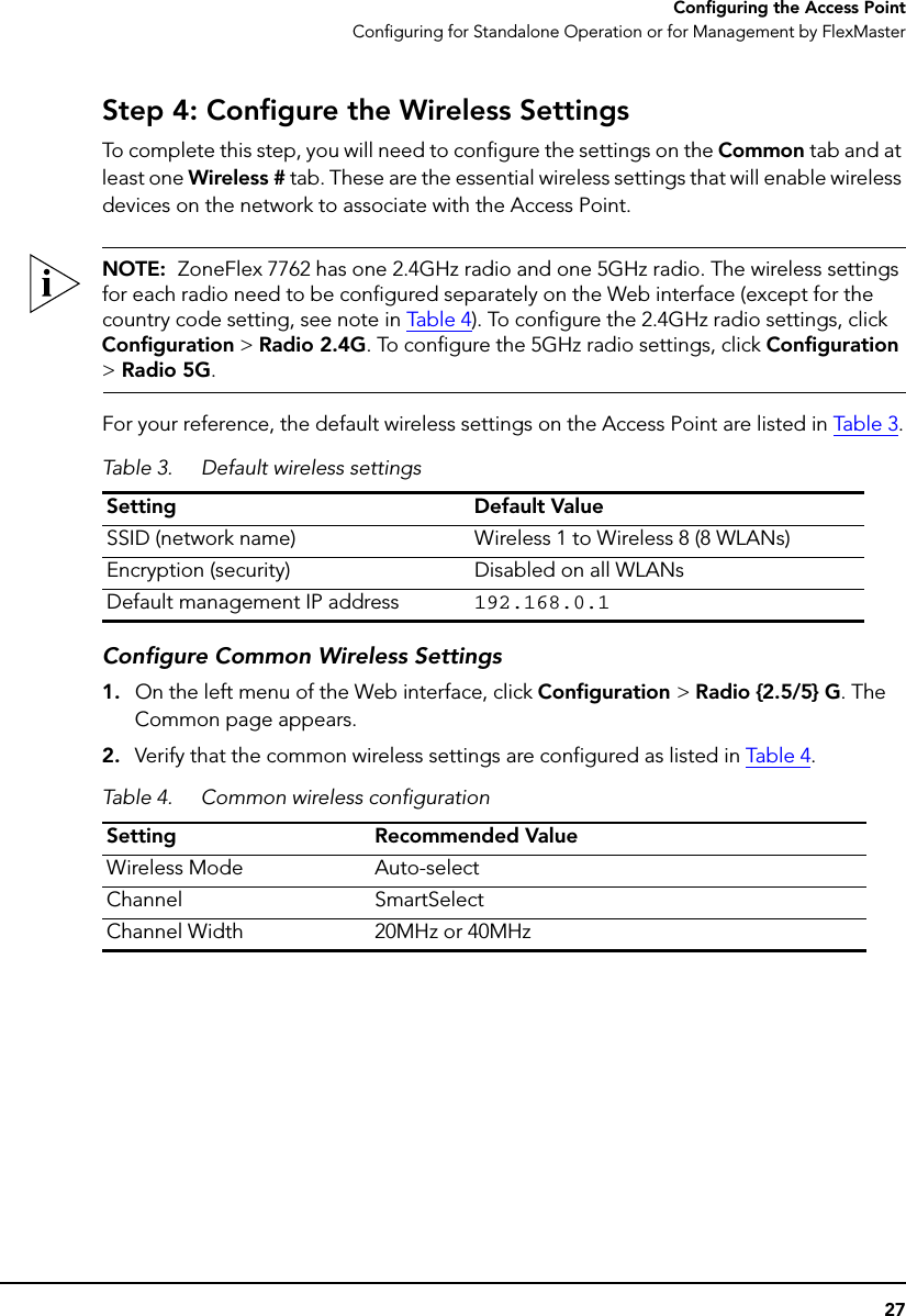
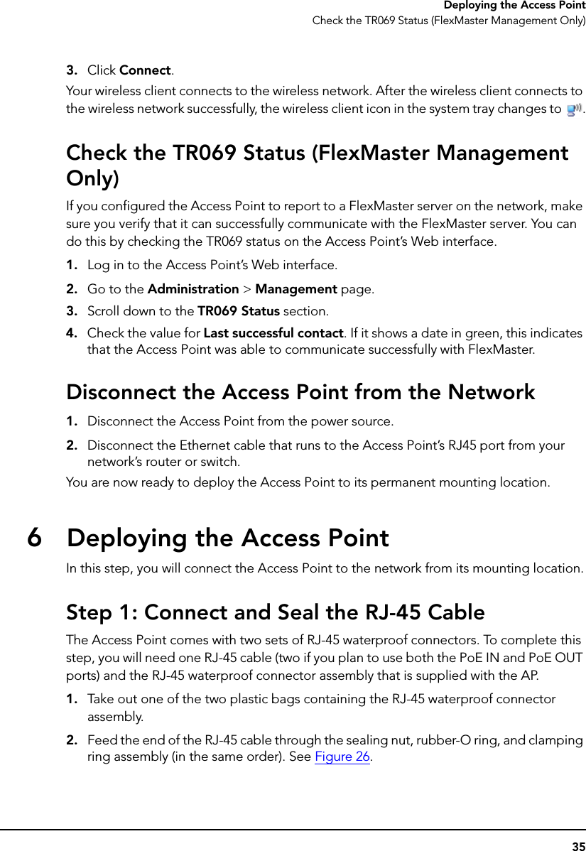
![Italy This product meets the National Radio Interface and the requirements specified in the National Frequency Allocation Table for Italy. Unless operating within the boundaries of the owner’s property, the use of this 2.4 GHz Wireless LAN product requires a ‘general authorization’. Please check with http://www.comunicazioni.it/ for more details. Questo prodotto è conforme alla specifiche di Interfaccia Radio Nazionali e rispetta il Piano Nazionale di ripartizione delle frequenze in Italia. Se non viene installato all’interno del proprio fondo, l’utilizzo di prodotti Wireless LAN a 2.4 GHz richiede una "Autorizzazione Generale". Consultare http://www.comunicazioni.it/ per maggiori dettagli. Belgium The Belgian Institute for Postal Services and Telecommunications (BIPT) must be notified of any outdoor wireless link having a range exceeding 300 meters. Please check http://www.bipt.be for more details. Draadloze verbindingen voor buitengebruik en met een reikwijdte van meer dan 300 meter dienen aangemeld te worden bij het Belgisch Instituut voor postdiensten en telecommunicatie (BIPT). Zie http://www.bipt.be voor meer gegevens. Les liaisons sans fil pour une utilisation en extérieur d’une distance supérieure à 300 mètres doivent être notifiées à l’Institut Belge des services Postaux et des Télécommunications (IBPT). Visitez http://www.ibpt.be pour de plus amples détails. Česky [Czech] Ruckus Wireless tímto prohlašuje, že tento Radio LAN je ve shodě se základními požadavky a dalšími příslušnými ustanoveními směrnice 1999/5/ES. Dansk [Danish] Undertegnede Ruckus Wireless erklærer herved, at følgende udstyr Radio LAN overholder de væsentlige krav og øvrige relevante krav i direktiv 1999/5/EF. Deutsch [German] Hiermit erklärt Ruckus Wireless, dass sich das Gerät Radio LAN in Übereinstimmung mit den grundlegenden Anforderungen und den übrigen einschlägigen Bestimmungen der Richtlinie 1999/5/EG befindet. Eesti [Estonian] Käesolevaga kinnitab Ruckus Wireless seadme Radio LAN vastavust direktiivi 1999/5/EÜ põhinõuetele ja nimetatud direktiivist tulenevatele teistele asjakohastele sätetele. English Hereby, Ruckus Wireless declares that this Radio LAN is in compliance with the essential requirements and other relevant provisions of Directive 1999/5/EC. Español [Spanish] Por medio de la presente Ruckus Wireless declara que el Radio LAN cumple con los requisitos esenciales y cualesquiera otras disposiciones aplicables o exigibles de la Directiva 1999/5/CE. Ελληνική [Greek] ΜΕ ΤΗΝ ΠΑΡΟΥΣΑ Ruckus Wireless ∆ΗΛΩΝΕΙ ΟΤΙ Radio LAN ΣΥΜΜΟΡΦΩΝΕΤΑΙ ΠΡΟΣ ΤΙΣ ΟΥΣΙΩ∆ΕΙΣ ΑΠΑΙΤΗΣΕΙΣ ΚΑΙ ΤΙΣ ΛΟΙΠΕΣ ΣΧΕΤΙΚΕΣ ∆ΙΑΤΑΞΕΙΣ ΤΗΣ Ο∆ΗΓΙΑΣ 1999/5/ΕΚ. Français [French] Par la présente Ruckus Wireless déclare que l'appareil Radio LAN est conforme aux exigences essentielles et aux autres dispositions pertinentes de la directive 1999/5/CE. Italiano [Italian] Con la presente Ruckus Wireless dichiara che questo Radio LAN è conforme ai requisiti essenziali ed alle altre disposizioni pertinenti stabilite dalla direttiva 1999/5/CE. Latviski [Latvian] Ar šo Ruckus Wireless deklarē, ka Radio LAN atbilst Direktīvas 1999/5/EK būtiskajām prasībām un citiem ar to saistītajiem noteikumiem. Lietuvių [Lithuanian] Šiuo Ruckus Wireless deklaruoja, kad šis Radio LAN atitinka esminius reikalavimus ir kitas 1999/5/EB Direktyvos nuostatas. Nederlands [Dutch] Hierbij verklaart Ruckus Wireless dat het toestel Radio LAN in overeenstemming is met de essentiële eisen en de andere relevante bepalingen van richtlijn 1999/5/EG. Malti [Maltese] Hawnhekk, Ruckus Wireless, jiddikjara li dan Radio LAN jikkonforma mal-ħtiġijiet essenzjali u ma provvedimenti oħrajn relevanti li hemm fid-Dirrettiva 1999/5/EC. Magyar [Hungarian] Alulírott, Ruckus Wireless nyilatkozom, hogy a Radio LAN megfelel a vonatkozó alapvetõ követelményeknek és az 1999/5/EC irányelv egyéb elõírásainak. Polski [Polish] Niniejszym Ruckus Wireless oświadcza, że Radio LAN jest zgodny z zasadniczymi wymogami oraz pozostałymi stosownymi postanowieniami Dyrektywy 1999/5/EC. Português [Portuguese] Ruckus Wireless declara que este Radio LAN está conforme com os requisitos essenciais e outras disposições da Directiva 1999/5/CE. Slovensko [Slovenian] Ruckus Wireless izjavlja, da je ta Radio LAN v skladu z bistvenimi zahtevami in ostalimi relevantnimi določili direktive 1999/5/ES. Slovensky [Slovak] Ruckus Wireless týmto vyhlasuje, že Radio LAN spĺňa základné požiadavky a všetky príslušné ustanovenia Smernice 1999/5/ES. Suomi [Finnish] Ruckus Wireless vakuuttaa täten että Radio LAN tyyppinen laite on direktiivin 1999/5/EY oleellisten vaatimusten ja sitä koskevien direktiivin muiden ehtojen mukainen. Svenska [Swedish] Härmed intygar Ruckus Wireless att denna Radio LAN står I överensstämmelse med de väsentliga egenskapskrav och övriga relevanta bestämmelser som framgår av direktiv 1999/5/EG. Íslenska [Icelandic] Hér með lýsir Ruckus Wireless yfir því að Radio LAN er í samræmi við grunnkröfur og aðrar kröfur, sem gerðar eru í tilskipun 1999/5/EC. Norsk [Norwegian] Ruckus Wireless erklærer herved at utstyret Radio LAN er i samsvar med de grunnleggende krav og øvrige relevante krav i direktiv 1999/5/EF. 800-70217-001-B](https://usermanual.wiki/Senao-Networks/ZF7762/User-Guide-1158109-Page-62.png)