SendFar Technology WPC-02005 Wireless LAN Card User Manual WPC 8110
SendFar Technology Co., Ltd. Wireless LAN Card WPC 8110
Contents
- 1. Manual
- 2. Revised Manual
Manual

A
Wireless LAN Card
User’s Manual
The user guide is fit for both Long Range Wireless LAN Card WPC-
8110 and Wireless LAN Card WPC-2110
i
■
Contents
CHAPTER 1. INTRODUCTION................................................................. 1
1.1 PACKAGE CONTENTS ............................................................................ 1
1.2 PC CARD DESCRIPTIONS ...................................................................... 1
1.3 SYSTEM REQUIREMENTS ....................................................................... 2
1.4 NETWORK CONFIGURATIONS ................................................................. 2
CHAPTER 2. INSTALLING DRIVERS & CLIENT UTILITY ..................... 4
2.1 INSTALLATION FOR WINDOWS 95/98/ME/2000/XP................................. 4
2.2 CHECKING AFTER INSTALLATION ............................................................ 9
2.3 WIRELESS LAN CLIENT UTILITY .......................................................... 11
2.4 UNINSTALLING DRIVER AND UTILITY ..................................................... 17
CHAPTER 3. CONNECTING TO A NETWORK..................................... 18
3.1 CHECKING AND ADDING CLIENT FOR MICROSOFT NETWORKS ............... 18
3.2 CHECKING AND ADDING NETBEUI ....................................................... 20
3.3 CHECKING AND ADDING TCP/IP .......................................................... 20
3.4 CHECKING AND ADDING FILE AND PRINTER SHARING FOR MICROSOFT
NETWORKS ................................................................................................... 22
3.5 CHECKING AND ADDING COMPUTER NAME & WORKGROUP NAME......... 22
CHAPTER 4. TROUBLESHOOTING...................................................... 23
CHAPTER 5. PRODUCT SPECIFICATIONS ......................................... 25
CHAPTER 6. REGULATORY COMPLIANCE INFORMATION ............. 26
1
Chapter 1. Introduction
This chapter describes the package contents, PC Card description, system
requirements, features & benefits, applications and network configurations
of our wireless LAN products.
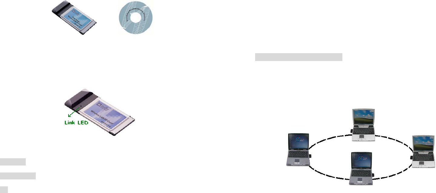
1.1 Package Contents
The PC Card package contains the following items as shown in Figure 1-1
1. One PC Card
2. One Installation CD
Figure 1-1
1.2 PC Card Descriptions
The PC Card is a standard PC Card that fits into any PCMCIA Card Type II
slot. The PC Card has a LED indicator as shown in Figure 1-2.
Figure 1-2
The LED shows three Link statuses:
Blinking –, When the PC Card operate in a Peer-to-Peer mode, no matter
the wireless is connected or not.
Solid Green – When the PC card setup a wireless connection with an
Access Point.
Off – No wireless activity.
2
1.3 System Requirements
Installation of the PC Card requires:
1. PC/AT compatible computer with PCMCIA Type II slot.
2. Windows 98//ME/2000/XP operating system environment.
3. Minimum 1.3M bytes free disk space for installing the PC Card driver
and utility program.
1.4 Network Configurations
To better understand how the wireless LAN products work together to
create a wireless network, it might be helpful to depict a few of the possible
wireless LAN PC card network configurations. The wireless LAN products
can be configured as:
1. Ad-hoc (or peer-to-peer) for departmental or SOHO LANs.
2. Infrastructure for enterprise LANs or IP Sharing for 56K/ISDN
TA/Cable/DSL Modem – Connect Internet and your SOHO network.
Ad-hoc (peer-to-peer) Mode
This is the simplest network configuration that several computers equipped
with the PC Cards that form a wireless network whenever they are within
range of one another (Figure 1-3). In ad-hoc mode, each client, is peer-to-
peer, would only have access to the resources of the other client and
requires no the access point. This is the easiest and least expensive way
for the SOHO to set up a wireless network.
Figure 1-3 A wireless Ad-hoc network
3
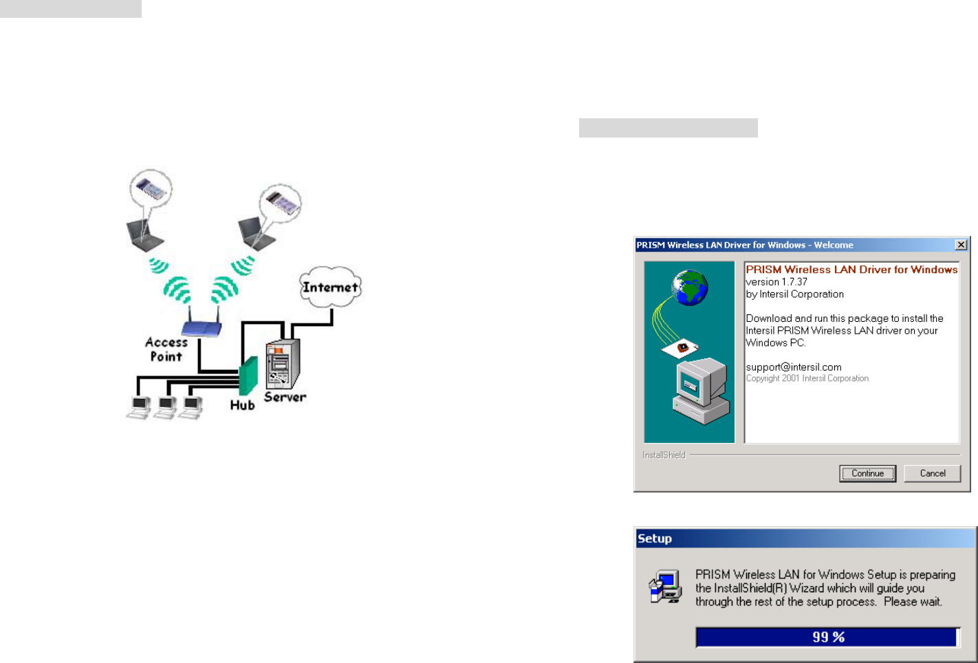
Infrastructure Mode
The infrastructure mode requires the use of an access point (AP). In this
mode, all wireless communications between two computers have to be via
the AP no matter the AP is wired to Ethernet network or stand-alone.
If wired to an Ethernet network as shown in Figure 1-4, the AP serves as a
bridge and provides the link between the server and the wireless clients.
The wireless clients can move freely throughout the coverage area of the
AP while remaining connected to the server. Since the AP is connected to
the wired network, each client would have access to server resources as
well as to other clients.
Figure 1-4 Infrastructure mode
4
Chapter 2. Installing Drivers & Client Utility
This chapter describes how to install the PC Card drivers and client utility
under Windows 95/98/ME/2000/XP.
2.1 Installation for Windows 95/98/ME/2000/XP
Installation Procedure:
1. Turn on your computer.
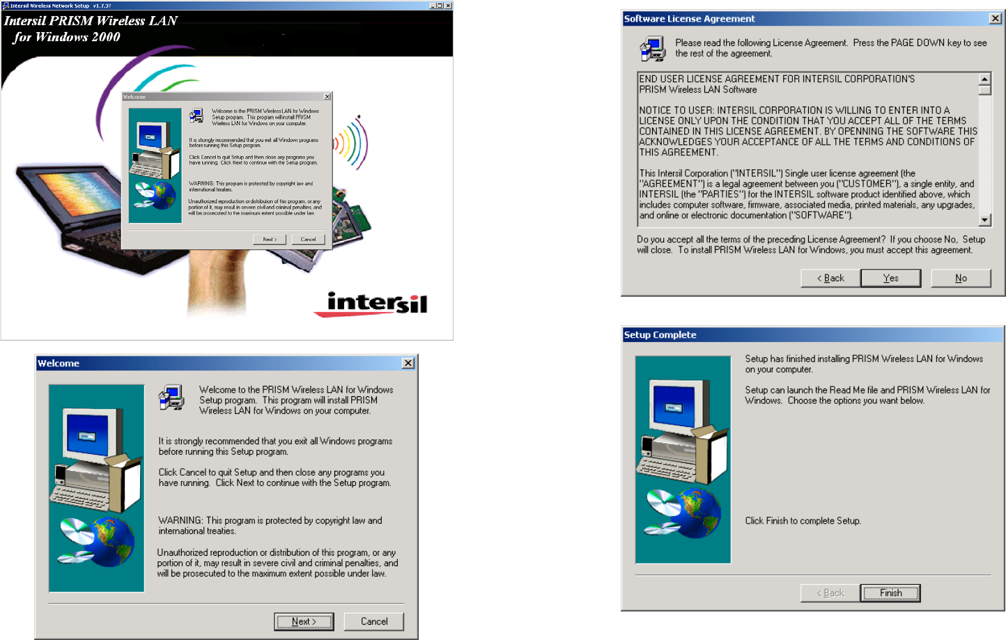
2. Insert the Wireless LAN Driver CD into your CD-ROM drive. Run it by
selecting RUN from the Start menu and running PrismWin.exe or just
double click the PrismWin.exe from CD-ROM drive.
3. The setup information will shown as Figure 2-1. Follow the instructions
as they appear.
Figure 2-1
5 6
4. Click Finish to complete setup and then restart your computer.
7
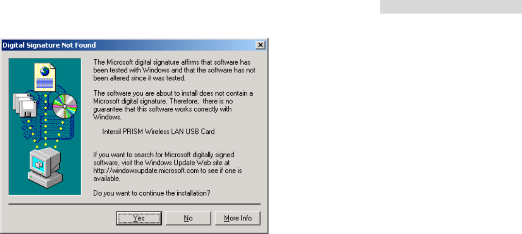
5. Insert the PC Card into the PCMCIA slot of your computer.
6. A warning message would pop up while installation, the message
shows this driver need the “digital signature”, and click the Yes button.
7. Make sure that the network protocol parameters are set correctly for
your computer. These include the IP address, subnet mask, gateway
and DNS. If you are unfamiliar with how to set network protocol
parameters, refer to Chapter 3 Connection to Network for details.
8. Restart your computer for changes to take effect.
Note
1. If your computer running Windows 95/98/ME/2000/NT installed
Wireless LAN PC card and you would like to upgrade to Windows XP,
you have to remove Wireless LAN PC card driver & utility from your
computer in advance to let the Wireless LAN PC card work with
Windows XP properly.
2. Please follow the procedure: click Start button, select Program, point
to Wireless LAN PC Card, and then click Uninstaller to uninstall the
driver and utility automatically
3. Once you finish removing the driver and utility, please refer to the
above installation procedure for Windows XP.
8
Uninstallation Procedure:
1. Insert the Wireless LAN PC Card into the PCMCIA slot.
2. Right click My Computer--->Select Properties.
3. On the Hardware tab, choose Device Manager, and click Network
Adapter.
4. Choose Wireless LAN PC Card and remove it.
5. After removing the Wireless LAN PC Card, restart your computer.
9
2.2 Checking after Installation
After installing the driver and utility, follow the steps below to check that
the PC Card is operating correctly.
1. Click the Start button, select Settings, and then click Control Panel.
2. In the Control Panel window, double-click the System icon, then
select the Device Manager tab.
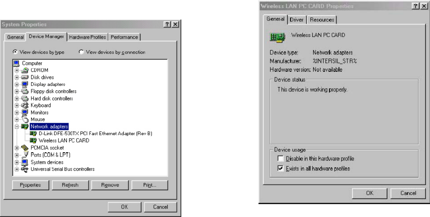
3. Double-click Network adapters, then select Wireless LAN PC CARD
as shown in Figure 2-3
Figure 2-3
4. Click the Properties button, then check the message. This device is
working properly is displayed for Device status as shown in Figure 2-
10
4.
5. If you find the Yellow (?) sign on the adapter or the above message is
not displayed, it shows the installation is not successful or the wireless
LAN PC Card is not operating properly. Uninstall and re-install the
driver, referring to Chapter 2-6 Uninstalling Driver and Utility.
Figure 2-4
11
2.3 Wireless LAN Client Utility
Wireless LAN Client Utility is used to display or change the PC Card
information about link, configuration, encryption, and utility/driver/firmware
version information. The client utility will also help you with site selection.
The client utility will be installed automatically after installing the driver and
utility. A new icon should appear in your Icon tray. If the icon changes to red
icon, it means the wireless is disconnection.
After finishing installing the driver and utility, the client utility will
automatically be executed and show a small green radio icon at the right
corner of Taskbar whenever the PC Card is inserted into the PC Card slot
of your computer. Double-click the radio icon to open the Wireless LAN
Client Utility window as shown in Figure 2-5. You can click the taps on the
top of the windows to select various screen messages. Below we explain
the use and meanings of the various screen messages.
Figure 2-5
12
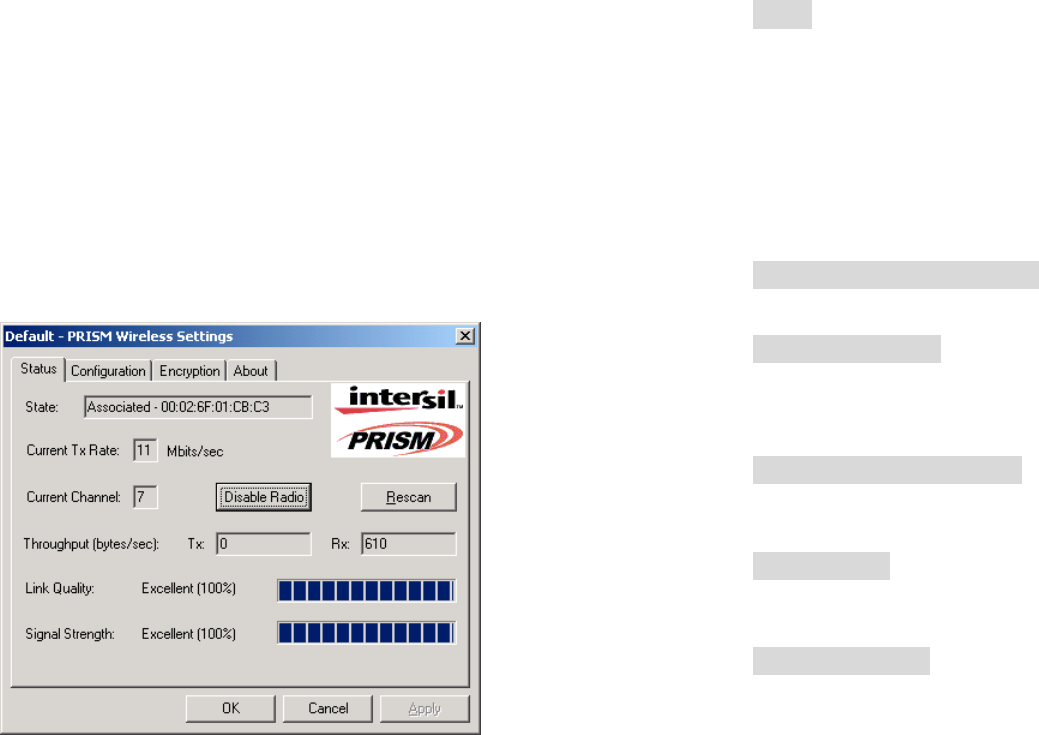
1. Link Info
State
Shows status information about the radio link, as shown in Figure 2-5
Associated BSSID – means the wireless client is connected to an access
point. BSSID is shown in the form of six hex digits which is the MAC
address of the access point.
Scanning – means the wireless client is searching for an available access
point in infrastructure mode.
Disconnected – means there are no access points or other wireless clients
(if communicating in Ad-hoc mode), or the PC Card is unplugged in your
computer.
Current Tx Rate (Mbits/s)
The data speed that wireless client is transmitting.
Current Channel
The operation radio frequency channel that wireless client is using in
infrastructure mode. In infrastructure mode, wireless client will always go
the same channel as their Access Point.
Throughput (Bytes/sec)
Tx: shows the outgoing (sent) data speed.
Rx: shows the incoming (received) data speed.
Link Quality
The bar shows the measured signal level and connection status. The
higher blue bar is, the better is radio signal received by the PC card.
Signal Strength
The bar shows signal strength level. The higher blue bar is, the more
powerful radio signal is received by the PC Card.
13
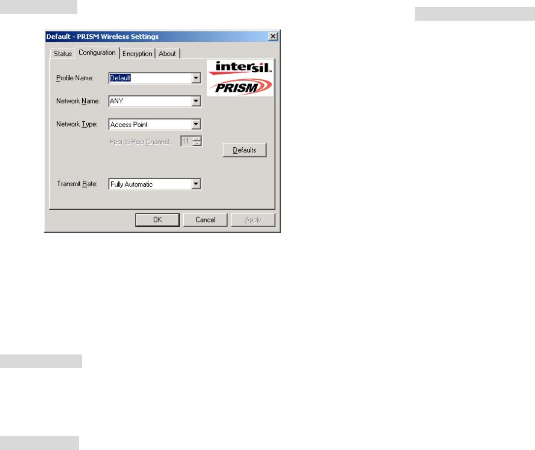
2. Configuration
Network Type
Selects one of the following network type, as shown in Figure 2-6.
Figure 2-6
Peer-to-Peer: this is the IEEE802.11 peer-to-peer mode of operation and
requires no the Access Point. When wireless clients are operated in this
mode, all wireless clients require the same SSID and don’t care the channel
number.
Access Point: this mode of operation requires the use of an Access Point.
In this mode, all wireless communications between computers have to be
via the Access Point. (Default setting is Access Point)
Network Name
Network Name (SSID) is an identification code required for communication
in a wireless LAN. You will only be able to connect with a wireless client
(Peer-to-Peer) or an Access Point (Infrastructure) which has the same
SSID. If the SSID of a PC Card is set as ANY, then the PC Card is possible
to be connected to all available Access Point. (Default setting is ANY)
Transmit Rate
Select the transmission rate at which the client transmits the data packets.
14
You can set this to Fully Automatic, 1Mbps, 2Mbps, Auto 1 or 2Mbps,
5.5Mbps, or 11Mbps. (Default setting is Fully Automatic)
Peer-to-Peer Channel
Select the operating radio frequency channel in 802.11 peer-to-peer mode.
15
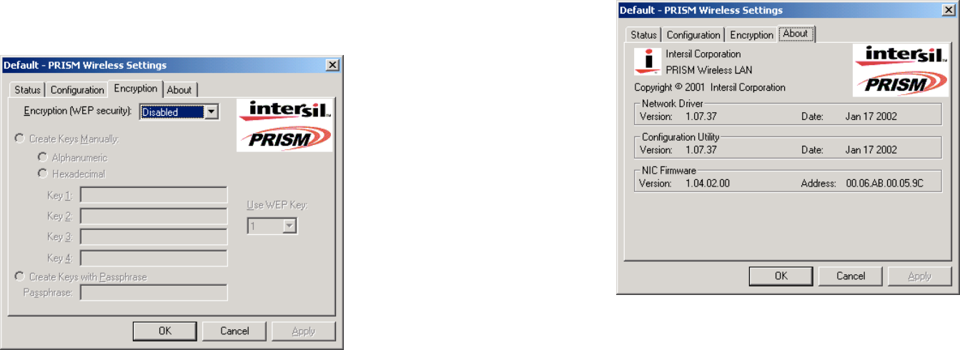
3. Encryption
If you require high security in transmission, you can select 64 or 128-bit
WEP (Wired Equivalent Privacy) key to encrypt data (Default setting is
Disable) as shown in Figure 2-7. WEP encrypts each frame transmitted
from the radio using one of the Keys from this panel. When you use WEP to
communicate with the other wireless clients, all the wireless devices in this
network must have the same encryption key or pass phrase.
Figure 2-7
This panel allows the entry of keys or pass phrase, which can then be
written to the driver and registry. Note that each key must consist of hex
digits, it means that only digit 0-9 and letters A-F are valid entries. If entered
incorrectly, program will not write keys to a driver.
16
4. About
About tab shows the product/driver/utility/PC Card firmware version as
shown in Figure 2-8. Users have to use this version number when
reporting their problems to technical support.
Figure 2-8
17
2.4 Uninstalling Driver and Utility
If the PC Card installation is unsuccessful for any reason, the best way to
solve the problem may be to completely uninstall the PC Card and its
software and repeat the installation procedure again.
Click the Start button, select Program/Wireless LAN PC Card, and then
click Uninstaller to uninstall the driver and utility. Uninstaller will
automatically uninstall and clear all drivers, utility, related settings installed
previously.
18
Chapter 3. Connecting to a Network
This chapter describes how to prepare for connection to network after
install the PC Card drivers and utility.
The following is required for all computers if you want to connect to a
network.
1. Check Client for Microsoft Networks is installed.
2. Check NetBEUI -> Wireless LAN PC Card installed.
3. Check TCP/IP -> Wireless LAN PC Card is installed.
4. Check file and printer sharing for Microsoft Networks.
5. Check computer name and workgroup name.
3.1 Checking and Adding Client for Microsoft
Networks
The Client for Microsoft Networks enables you to connect to other Microsoft
Windows computers and servers and use the files and printers shared on
them. If you work on Microsoft network environment, you need to set up
Client for Microsoft Networks.
1. After finishing installing the driver & utility and rebooting the computer
as described in Chapter 2. The computer will show a dialog box titled
Enter Network Password dialog box. Enter your password if it had
been set or just click Cancel.
2. Click Start button, select Settings and then click Control Panel to
open the Control Panel window.
3. In the Control Panel window, double-click the Network icon to open
the Network dialog box.
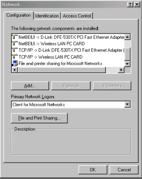
4. . Select Configuration tab to check Client for Microsoft Networks is
installed as shown in Figure 3-1. If no, click the Add button. Select
Client and click the Add button.
5. Select Microsoft for Manufacturer and Client for Microsoft Networks
for Network Client, and then click OK.
19
Figure 3-1
20
3.2 Checking and Adding NetBEUI
NetBEUI is a protocol you can use to connect to Windows NT, Windows for
Workgroups, or LAN Manager servers. If you work on Microsoft network
environment, you need to set up NetBEUI protocol.
1. Repeat the step 2 and 3 of Chapter 3-1 Checking and Adding Client for
Microsoft Networks.
2. Select Configuration tab to check NetBEUI -> Wireless LAN PC Card is
installed. If no, click the Add button. Select Protocol and click the Add button.
3. Select Microsoft for Manufacturer and NetBEUI for Network Protocol, and then
click OK.
3.3 Checking and Adding TCP/IP
TCP/IP is the protocol you use to connect to the Internet and wide-area
networks. If you want to connect to Internet, you need to set up TCP/IP
protocol.
1. Repeat the step 2 and 3 of Chapter 3-1 Checking and Adding Client for
Microsoft Networks.
2. Select Configuration tab to check TCP/IP -> Wireless LAN PC Card
is installed. If no, click the Add button. Select Protocol and click the
Add button.
3. Select Microsoft for Manufacturer and TCP/IP for Network Protocol,
and then click OK.
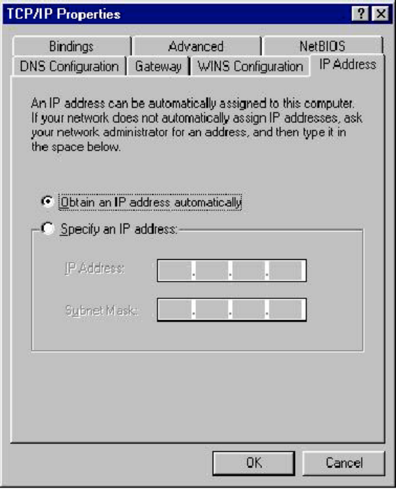
4. If yes, double-click TCP/IP -> Wireless LAN PC Card to open TCP/IP
properties as shown in Figure 3-2. Due to different network
applications there are many different settings here. You can select
either Obtain an IP address automatically or Specify an IP address.
If you use the Specify and IP address, then you need to enter an IP
address, Subnet Mask, Gateway IP address, and DNS Server IP
address for connecting to Internet.
21
Figure 3-2
22
3.4 Checking and Adding File and Printer
Sharing for Microsoft Networks
File and printer sharing for Microsoft networks gives you the ability to share
your files or printers with Windows NT and Windows for Workgroups
computers. If you want to share your files or printers with Microsoft
networks, you need to set up this service.
1. Repeat the step 2 and 3 of Chapter 3-1 Checking and Adding Client for
Microsoft Networks.
2. Select Configuration tab to check File and printer sharing for Microsoft
Networks is installed. If no, click the File and Printer Sharing button.
3. In the File and Print Sharing window, select what you need, and click OK. File
and printer sharing for Microsoft Networks, and then click OK.
3.5 Checking and Adding Computer Name &
Workgroup Name
Windows uses the computer name and workgroup name to identify your
computer on the network. Please enter an unique name for your computer,
the workgroup it will appear in, and a short description of the computer.
1. Repeat the step 2 and 3 of Chapter 3-1 Checking and Adding Client for
Microsoft Networks.
2. . Select Identification tab (Windows 98) or User Information tab (Windows 95)
to check the computer name, workgroup and computer description are entered.
If no, enter a computer name, a workgroup name and then click OK. The
description field may be left blank. If you want to share data with other persons,
make sure you have the same workgroup name.

23
Chapter 4. Troubleshooting
This chapter describes the problems and corresponding solutions that may
occur when installing a PC Card.
Symptom Solution
Windows does not
detect the PC Card
when installed.
Verify that the PC Card is properly inserted into
the PC Card slot.
Check whether the computer has a Plug and
Play BIOS.
Windows 95/98/ME/2000/XP might not detect the
PC Card if a previous installation of the PC Card
was cancelled before it was finished. Remove the
previous driver, and redo the installation again.
Driver fails to load A resource conflict could exist.
For Windows 95/98/ME/2000, use the Device
Manager to resolve resource conflicts. Select
System from the Control Panel, then click on
the Device Manager tab.
Device conflict on a
Windows system
A device conflict under Windows 95/98/ME/2000
may be related to the PC Card.
For Windows 95/98/ME/2000, use the Computer
properties to identify the used I/O port addresses
and IRQ values.
If there is a device conflict, select alternative
settings for I/O Base Address or IRQ values. If
you know which device is conflicting with the PC
Card, you have the option of changing that
device’s I/O address or IRQ instead of changing
the PC Card.
No resource conflicts
were detected, but the
wireless station does not
attach to the network
Verify that the SSID of the PC Card matches that
of the access point. Use the Network
Configuration Properties Application in the
Control Panel to modify the SSID.
Verify that the Network Mode of the PC Card is
24
configured correctly.
Nonfunctioning card LED The PC Card is not powered on. The cause may
be:
--No Driver loaded or installed.
--Card – Driver mismatch which prevented the
driver from loading.
--Device conflict which prevented the driver from
loading.
Actions:
--Verify that a driver has been installed.
--Determine if there is a conflict with another
device.
Weak signal or
intermittent connection
Try reorienting the antenna. The PC Card
antenna is attached to the end of the PC Card.
For best use of the antenna:
Keep the area around the antenna clear from
materials that could block radio transmission,
such as metal objects, electronic devices, and
cordless telephones.
If your signal is weak, change the direction of the
antenna slightly.
If necessary, move your notebook computer a
few inches to find a better signal.
Use the Link Quality and Signal Strength display
in the Client Utility to determine the best
location and orientation for a network connection.

25
Chapter 5. Product Specifications
General
Radio Data Rate 11, 5.5, 2 and 1 Mbps, Auto Fallback
Operating Voltage 3.3V/5V
Regulation Certifications FCC Part 15/UL, ETSI 300/328/CE
Compatibility Fully interoperable with IEEE802.11b compliant products
LED Indicator RF Link activity
Network Information
Network Architecture Support ad-hoc, peer-to-peer networks and
infrastructure communications to wired Ethernet networks via Access Point
Drivers Windows 95/98/ME/2000/XP
Access Protocol CSMA/CA
Roaming IEEE802.11b compliant
Security 64/128-bit WEP data encryption
Radio
Frequency Band 2.4 – 2.484 GHz
Radio Type Direct Sequence Spread Spectrum (DSSS)
Modulation CCK (11, 5.5Mbps), DQPSK (2Mbps), DBPSK (1Mbps)
Operation Channels 11 for North America, 14 for Japan, 13 for Europe, 2
for Spain, 4 for France
RF Output Power 19dBm (WPC-8110), 13dBm (WPC-2110)
Sensitivity @FER=0.08 11 Mbps <-85dBm (WPC-8110), 83dBm(WPC-
2110)
5.5 Mbps<-88dBm (WPC-8110), 86dBm (WPC-2110)
2 Mbps <-91dBm (WPC-8110), 89dBm (WPC-2110)
1 Mbps <-93dBm (WPC-8110), 91dBm (WPC-2110)
Environmental
Temperature Range 0 to 55 C (operating), -20 to 75 C (storage)
Humidity (non-condensing) 10% to 95% typical
Physical Specifications
Form Factor PCMCIA Type II PC Card
Dimensions 118.5(L)mm * 54.5(W)mm * 9.2(H)mm
Weight 45 g
26
Chapter 6. Regulatory Compliance Information
Radio Frequency Interference Requirements
This device complies with Part 15 of FCC Rules and Canada RSS-210.
Operation is subject to the following conditions:
1. This device may not cause harmful interference.
2. This device must accept any interference received, including interference that
may cause undesired operation.
3. This transmitter must not be co-located or operating in conjunction with any
other antenna or transmitter.
4. Since the module is installed inside the end product, the end product should be
affixed a label on visible area showing that this product contains a RF module,
and also its FCC ID.
Interference Statement
This equipment has been tested and found to comply with the limits for a
Class B digital device, pursuant to Part 15 of the FCC Rules, These limits
are designed to provide reasonable protection against harmful interference
in a residential installation. This equipment generates, uses and can radiate
radio frequency energy and, if not installed and used in accordance with the
instructions, may cause harmful interference to radio communications.
However, there is no guarantee that interference will not occur in a
particular installation. If this equipment does cause harmful interference to
radio or television reception, which can be determined by turning the
equipment off and on, the user is encouraged to try to correct the
interference by one of the following measures:
z Reorient or relocate the receiving antenna.
z Increase the separation between the equipment and receiver.
z Connect the equipment into an outlet on a circuit different from that to
which the receiver is connected.
z Consult the dealer or an experienced radio/TV technician for help.
FCC Caution
Any changes or modifications not expressly approved by the party
responsible for compliance could void the user’s authority to operate this
equipment.