Sendum Wireless 6055M-ET300 GPS tracking device User Manual Manual
Sendum Wireless Corp. GPS tracking device Manual
Manual
QUICK INSTALLATION GUIDE
© 2009 BI Incorporated
8-90-00130-0, Revision A

BI ExacuTrack® One Quick Installation Guide
Copyright © 2009, BI Incorporated
All Rights Reserved
Printed in USA
BI prepared this guide for use by BI customers only. All comments concerning the
contents of this guide should be directed to BI’s Marketing Department, 6400 Lookout
Road, Boulder, CO 80301, USA. No part of this work covered by copyright may be
reproduced in any form either graphically, electronically, mechanically; including
photocopying, recording, taping, or storage in an information retrieval system without
prior written permission from BI.
Trademarks and Patents
The following are registered trademarks of BI Incorporated:
• BI
• BIlogo
• BIExacuTrack
• BIExacuTracklogo
Technical Support
For technical support call:
BI Incorporated
800 Main Street, Suite 501
Anderson, Indiana 46016
1-800-666-3145
FAX 765-649-3148
Waste Electrical and Electronic Equipment (WEEE)
All electrical products that reach the duration of their functioning capabilities
must be returned to BI Incorporated for recycling.

CONTENTS
Introduction . . . . . . . . . . . . . . . . . . . . . . . . . . . . . . . . . . . . . . . . . . . . . . . . .3
Parts. . . . . . . . . . . . . . . . . . . . . . . . . . . . . . . . . . . . . . . . . . . . . . . . . . . . . . . . .4
Assembling ..................................................5
Sizing. . . . . . . . . . . . . . . . . . . . . . . . . . . . . . . . . . . . . . . . . . . . . . . . . . . . . . . .8
Attaching. . . . . . . . . . . . . . . . . . . . . . . . . . . . . . . . . . . . . . . . . . . . . . . . . . 10
Confirmation ..............................................12
Removal/Battery Replacement . . . . . . . . . . . . . . . . . . . . . . . . . . . . . 13
Cleaning & Storage ........................................16
•8-90-00130-0,RevisionA
CLEANING & STORAGE
After removing the tracking unit from the client’s ankle, clean the
unit by wiping the case with a soft cloth. You can use Lysol as a
disinfectant if needed. Do not use Pinesol or any cleaning products
containing pine oil, as these solvents may damage the plastic body.
Store the tracking unit in its original shipping case. As an alternative,
you can clean the tracking unit in a standard dishwasher.
16•BIExacuTrackOneQuickInstallationGuide•8-90-00130-0,RevisionA
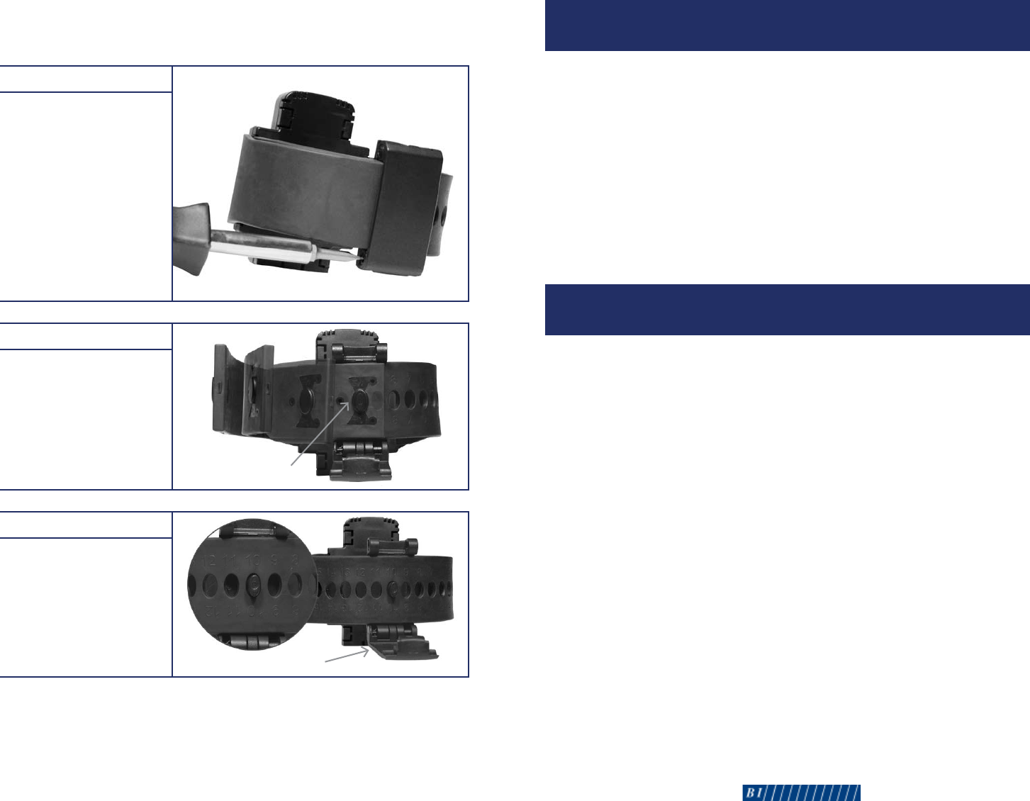
Step 4
If you are replacing the
battery, insert your cutting
tool into each locking
mechanism on the backplate.
Squeeze your cutting tool
to disengage the locking
mechanisms. Remove and
discard the backplate.
Step 5
Using a standard
screwdriver, turn the battery
hatch counter-clockwise to
the unlocked position, and
remove the battery hatch.
Step 6
Remove the battery from
the battery well.
To install a new battery,
follow steps 1 and 2 under
“To assemble the tracking
unit” on page 5.
•8-90-00130-0,RevisionA•15
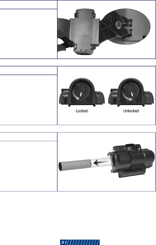
Step 1
While the tracking unit is
still on the client’s ankle,
insert a screwdriver into
the notched grooves on
the locking pins. Turn
the screwdriver counter-
clockwise until the hinge
assembly is released. You
must complete this step for
both locking pins on each
side of the hinge assembly.
Discard the locking pins.
Step 2
Pull firmly on the fixed
strap to release the
fiber-optic connector
from the hinge post.
Step 3
Remove the hinge assembly
from the adjustable strap.
Clean the hinge assembly
with Lysol or similar
product, and store the
assembly for reuse.
To Remove the Tracking Unit: Steps 1-6 >
WARNING! Do NOT cut the strap to remove the tracking unit from the
client’s ankle.
14•BIExacuTrackOneQuickInstallationGuide•8-90-00130-0,RevisionA
INTRODUCTION
The ExacuTrack One tracking unit is a GPS device secured around the
client’s ankle. This device includes the following features:
• GPSReceiver
• AFLTLocationTechnology
• AssistedGPSTechnology
• RFReceiver
Use this guide to properly install the tracking unit on your client’s ankle.
Fordetailedinformationaboutthisproduct,seetheBI ExacuTrack One
Officer’s Reference Guide.
INSTALLATION
The installation process for the ExacuTrack One tracking unit involves
three separate steps:
• Assemblingthetrackingunit
• Sizingforpropert
• Attachingthetrackingunittotheclient
You will need both a standard and Phillips screwdriver to complete the
installation. Discard the locking pins after each use, and discard the
backplate after each battery replacement; locking pins and backplates are
available by order from BI Incorporated. All other supplies - including the
straps - are reusable and should not be discarded. Keep in mind that the
battery should be replaced after 2 years of continuous use.
•8-90-00130-0,RevisionA•3
Hinge Assembly
Fiber-Optic Connector
4•BIExacuTrackOneQuickInstallationGuide•8-90-00130-0,RevisionA
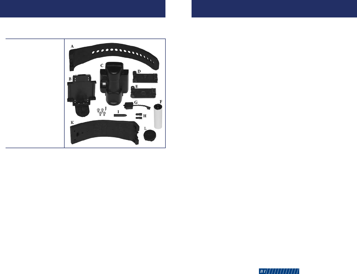
A. Adjustable Strap
B. Backplate
C. Unit Case
D. Male Hinge
E. FemaleHinge
F. Battery
G. Charging Port Cover
H. Locking Pins (2)
I. Joint Pin
J. Screws (4)
K. FixedStrap
L. Battery Hatch
PARTS
Before assembling the tracking unit, verify that you have the
necessary parts:
REMOVAL/BATTERY REPLACEMENT
If you discharge a client from the program, the tracking unit must be
removed. You may also need to remove the tracking unit if the battery,
straps, hinge assembly, or the unit case require replacement.
The following parts are reusable:
• UnitCase
• Battery
• BatteryHatch
• FixedStrap
• AdjustableStrap
• HingeAssembly
•8-90-00130-0,RevisionA•13
CONFIRMATION
SELFTEST
After installation, the tracking unit initiates a series of self-tests to
make sure the system is functioning properly. These tests only last
approximately 3 seconds.
STATUS MONITORING
After successful completion of the self-test, the tracking unit initiates
location acquisition and checks for cellular service availability. During
this period, the tracking unit also monitors battery and tamper status.
If using a beacon, the tracking unit will search for the beacon’s signal,
which is transmitted every 10-13 seconds.
HOST COMMUNICATION
While continuing to monitor equipment status, the tracking unit calls
the central monitoring computer to download configuration data.
During this communication with the central monitoring computer,
the tracking unit reports a successful installation. The following
messages will appear in the system software when the tracking unit is
successfully installed:
• TrackerRestart
• TrackerBatteryRestore
• TrackerTamperRestore
12•BIExacuTrackOneQuickInstallationGuide•8-90-00130-0,RevisionA
ASSEMBLING: STEPS 110
To Assemble the Tracking Unit >
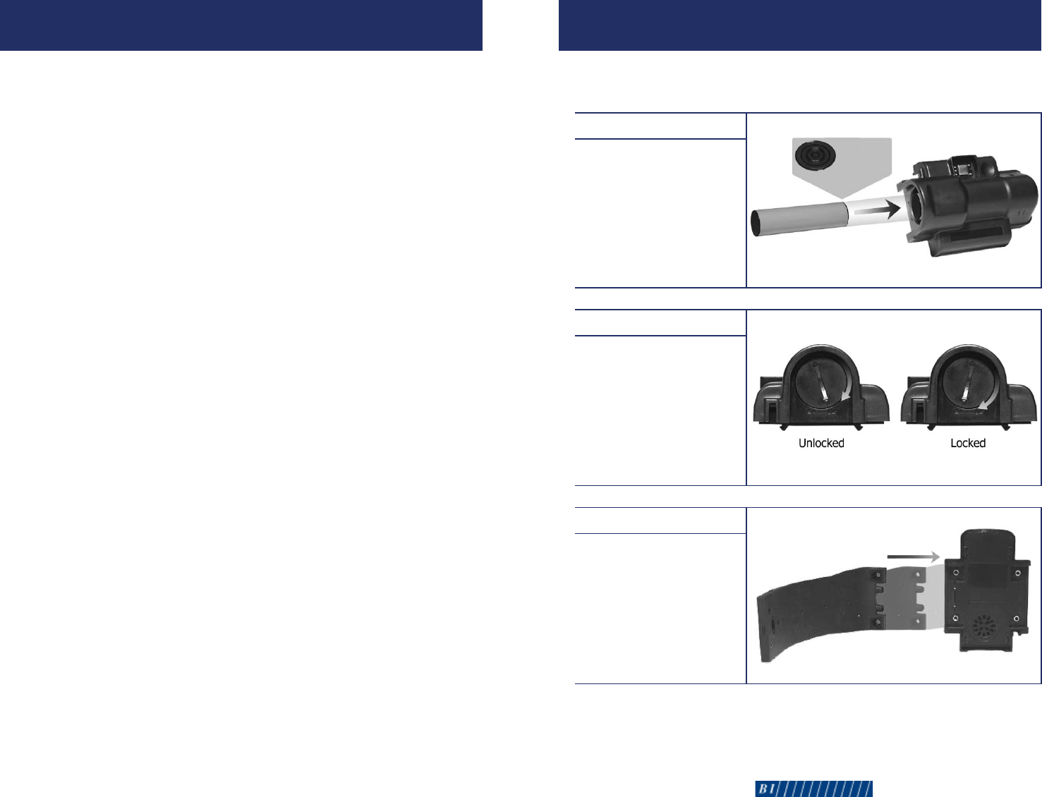
Step 1
Insert the battery into
the battery well with the
gold connection rings
facing toward the top of
the unit case.
Step 2
Position one of the
battery hatch alignment
arrows toward the
unlocked position. Using
a screwdriver, apply force
while turning the battery
hatch clockwise until it
reaches the locked position.
Step 3
Slide the fixed strap into
the fiber-optic connection
bay opposite of the
charging port.
•8-90-00130-0,RevisionA•5
Gold
Connection
Rings
6•BIExacuTrackOneQuickInstallationGuide•8-90-00130-0,RevisionA
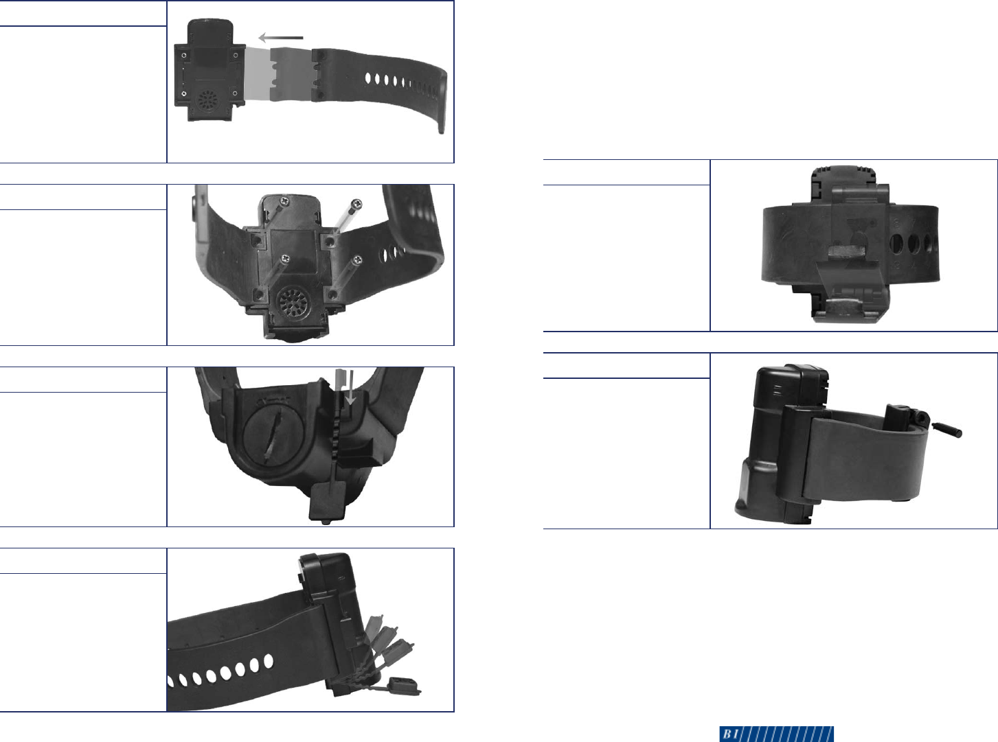
Step 4
Slide the adjustable strap
into the other fiber-optic
connection bay.
Step 5
Using a Phillips screwdriver,
secure the straps to the
unit case with the provided
screws. Place one screw in
each strap hole, and turn
each screw clockwise until
you feel resistance.
Step 6
Slide the end of the
charging port cover into the
slot on the bottom of the
unit case.
Step 7
Insert the charging port
cover into the charging port
on the front of the unit case.
To Assemble the Tracking Unit (cont.) >
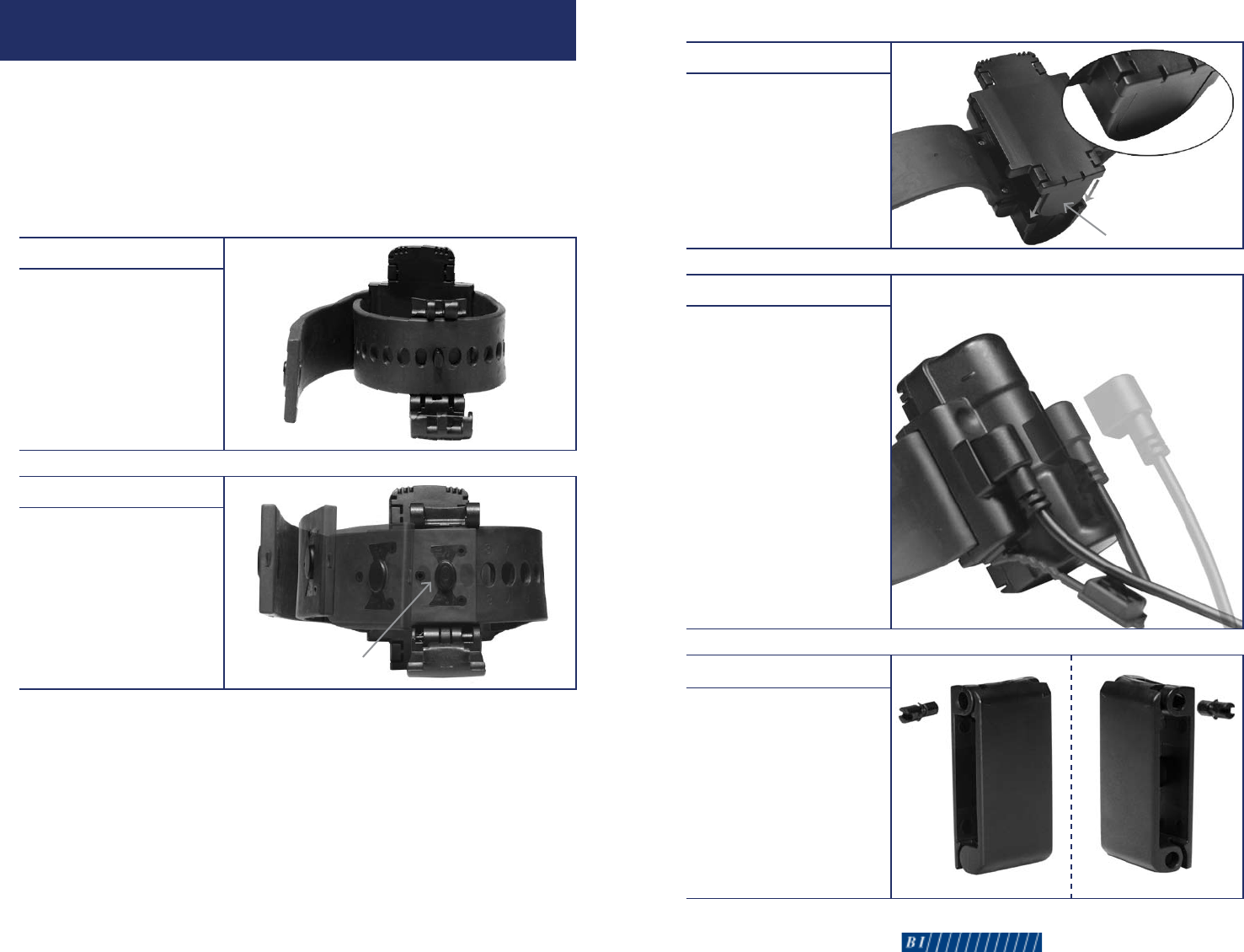
Step 3
Close the hinge assembly
around the straps until the
locking holes are aligned.
Step 4
Slide the joint pin through
the locking holes until it is
flush with both hinges.
•8-90-00130-0,RevisionA•11
Battery Cover
10•BIExacuTrackOneQuickInstallationGuide•8-90-00130-0,RevisionA
Step 1
Wrap the tracking unit
around the client’s ankle
as you did in step 1 of the
previous section.
Step 2
Align the hinge post with
the fiber-optic connector on
the fixed strap. Press firmly
on the fixed strap to hold
both straps in place.
ATTACHING: STEPS 14
When attaching the tracking unit to the client, keep the following
requirements in mind:
•Thestrapsizingnumbersmustfaceoutward(awayfromtheleg).
•Thetrackingunitmustbeintheuprightposition.
To Attach the Tracking Unit >
Fiber-Optic Connector
Step 8
Connect the backplate to
the back of the unit case,
ensuring the battery cover
slides into the groove on
the bottom of the unit case.
You will hear a distinct
click when the backplate is
properly attached.
Step 9
Place the unit upright on a
level, non-metallic surface.
Plug the power supply into
a wall outlet, and plug the
magnetic power adapter into
the charging port. Wait for an
audible tone (approximately
20 seconds). Once this tone
occurs, unplug the magnetic
power adapter. If all three LEDs
begin flashing, charge the unit
for a few minutes, and wait for
the tone. If you do not hear
an audible tone, reinstall the
battery and a new backplate,
and repeat this process.
Step 10
Assemble the male and
female hinges using the
locking pins. Pressing firmly,
insert a locking pin into
both sides of the hinge
assembly. The wing-tipped
ends of the locking pins
must be inserted first. This
piece is now referred to as
the hinge assembly.
•8-90-00130-0,RevisionA•7
Side 1 Side 2
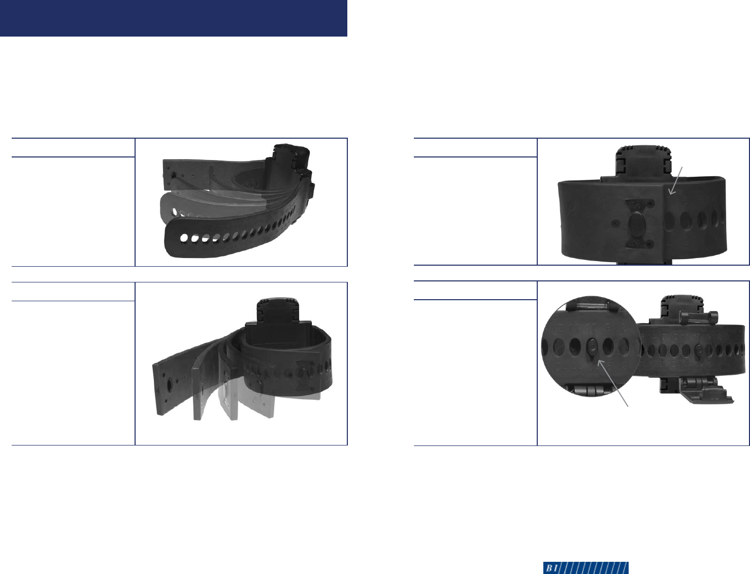
Step 3
Note the sizing number on
the adjustable strap that is
closest to the fixed strap.
Step 4
Remove the unit from
the client’s ankle.
Slide the post on the hinge
assembly into the sizing
hole numbered three more
than the number you noted
instep3.Forexample,if
you noted the strap sizing
number 7 in step 3, you will
slide the hinge post into the
strap hole numbered 10.
Post
Sizing Number
•8-90-00130-0,RevisionA•98•BIExacuTrackOneQuickInstallationGuide•8-90-00130-0,RevisionA
SIZING: STEPS 14
Size the tracking unit while the client is standing. The tracking unit must
be installed on the narrowest part of the bare ankle. When properly
installed, the tracking unit should meet resistance when rotated around
the front and back side of the ankle.
To Size the Tracking Unit >
Step 1
Wrap the adjustable strap
around the client’s ankle
and under the fixed strap.
Step 2
Wrap the fixed strap around
the client’s ankle and over
the adjustable strap.
Fixed Strap
Adjustable Strap

CLEANING & STORAGE
After removing the tracking unit from the client’s ankle, clean the
unit by wiping the case with a soft cloth. You can use Lysol as a
disinfectant if needed. Do not use Pinesol or any cleaning products
containing pine oil, as these solvents may damage the plastic body.
Store the tracking unit in its original shipping case. As an alternative,
you can clean the tracking unit in a standard dishwasher.
16 • BI ExacuTrack One Quick Installation Guide • 8-90-00130-0, Revision A
FCC NOTICES
1. Changes or modications not expressly approved by the party responsible for compliance
could void the user’s authority to operate the equipment.
2 This device complies with part 15 of the FCC Rules. Operation is subject to the condition that
this device does not cause harmful interference.
3. THIS DEVICE MEETS THE GOVERNMENT’S REQUIREMENTS FOR EXPOSURE TO RADIOWAVES.
This ankle device is a radio transmitter and receiver. It is designed and manufactured
not to exceed the emission limits for exposure to radio-frequency (RF) energy.These
limits are part of comprehensive guidelines and establish permitted levels of RF
energy for the general population.The guidelines are based on standards that were
developed by independent scientic organizations through periodic and thorough
evaluation of scientic studies. These guidelines include a substantial safety margin
designed to ensure the safety of all persons, regardless of age and health.
The exposure standard for this ankle bracelet employs a unit of measurement known as the
Specic Absorption Rate, or SAR.The SAR limit set by public authorities such as the
Federal Communications Commission of the US Government (FCC), or by Industry
Canada, is 4 W/kg averaged over 10 gram of body tissue. Tests for SAR are
conducted using standard operating positions with the transmitting at its
highest certied power level in all tested frequency bands.
Although the SAR is determined at the highest certied power level, the actual SAR
level of the ankle bracelet while operating can be well below the maximum value.This is
because the ankle bracelet is designed to operate at multiple power levels so as to use
only the power required to reach the network. In general, the closer you are to a
wireless base station antenna, the lower the power output of the ankle .
4. IC Manual requirements
This Class B * digital apparatus complies with Canadian ICES-003.