Senior Technologies BCP1 A pressure sensing switch in a bed or chair pad controls RF messages in the BedCheck Cordless Pad Transmitter User Manual
Senior Technologies Inc A pressure sensing switch in a bed or chair pad controls RF messages in the BedCheck Cordless Pad Transmitter
User Manual
[Safe. Secure. Efficient.]
Bed-Check® Cordless
Fall Management System
Setup & User Guide

Copyright Information
All content herein is the property of STANLEY Healthcare, its Affiliates, or
their content suppliers and is protected by United States and international
copyright laws. The compilation of all content is likewise the exclusive
property of STANLEY Healthcare (or the Affiliate identified in any copyright
notice) and is protected by United States and international copyright laws.
The trademarks, service marks and logos (the ‘Trademarks’) used and
displayed in this publication are registered and unregistered Trademarks
of STANLEY Healthcare, its Affiliates and others. Nothing herein should
be construed as granting, by implication, estoppel or otherwise, any
license or right to use any Trademark displayed herein without the prior
consent of the Trademark owner. STANLEY and the STANLEY design are
two of the trademarks owned by STANLEY Healthcare and/or its Affiliates
(“STANLEY Trademarks”). STANLEY Trademarks may not be used in
connection with any product or service that is not manufactured by or
under license from STANLEY Healthcare or its appropriate Affiliate.
Important Recommendation
STANLEY Healthcare’s systems are designed to assist staff in providing
a high degree of safety for people and assets and therefore should be
used as a component of a comprehensive safety program of policies,
procedures, and processes. As with every safety system, STANLEY
Healthcare highly recommends regular system operational checks to
verify functional integrity.
Warnings and Cautions
FAILURE TO HEED THE FOLLOWING “CAUTIONS” COULD RESULT IN HARM TO
YOUR SYSTEM OR CAUSE IT TO FUNCTION IMPROPERLY, INTERMITTENTLY, OR
NOT AT ALL.
• Use the Bed-Check Monitor only with approved accessories.
• Turn Monitors and Transmitters o before storing them away.
• Remove batteries immediately when the Monitor is not in use to avoid
battery power loss.
• Use care when connecting the Bed-Check Transmitter and Sensormat
pads. Gently remove or connect cords. Pulling on cords may damage
them and/or result in system failure.
CAUTION

FAILURE TO HEED THE FOLLOWING WARNINGS COULD RESULT IN INJURY TO
OR THE DEATH OF PERSONS IN YOUR CARE.
• Ensure that the Transmitter is properly connected to the cable inside the
pouch of the Sensormat® pad.
• Check that the Transmitter is switched on and that the status LED on the
Monitor ashes GREEN for at least 1 second when the Monitor button
is pressed, or the status LED ashes GREEN for 0.5 seconds once per
minute to indicate that it is monitoring the person.
• A low battery condition in the pad Transmitter is indicated by the status
LED on the Monitor blinking YELLOW twice every minute or when the
Monitor button is pressed. Change the Transmitter immediately.
• A low battery condition in the Monitor is indicated by the status LED
blinking YELLOW once every minute or when the Monitor button is
pressed. Change the batteries in the Monitor immediately.
• Do not use the Transmitter past the expiration date.
• When the pad has expired, check the expiration date on the Transmitter.
If the date has passed, dispose of the Transmitter with the pad. If the
Transmitter has not yet expired, you may reuse it.
• Test the Bed-Check Monitor and Sensormat pad before each use
and inspect the cords and pads for signs of damage. Replace any
components with signs of wear or damage immediately.
• Do not place the monitor within 1 ft. (0.3m) of and facing the resident.
Placing the Monitor on a wheelchair back is acceptable as long as the
monitor is facing away from the resident.
• The Bed-Check Monitor is only one part of your facility’s fall
management program. The Bed-Check Monitor is not a substitute for
proper nursing care or routine visual monitoring by caregivers. The
eectiveness of the Bed-Check Monitor relies entirely on an immediate
response by the caregiver to the Bed-Check Monitor system alarm.
• The Bed-Check Monitor system will not stop a person from leaving a
bed or chair. It is intended only to alert a caregiver that a patient or
resident may need assistance. Other interventions may be required.
• Keep the Sensormat pad at at all times. Folding the pad may damage
it. Do not use the pad if it has been folded.
• Do not immerse the Sensormat pads in liquids. The pad will not
operate properly if the pad is exposed to excessive liquids. If the pad is
immersed in liquid, discard it immediately.
WARNING

iv Bed-Check® Fall Management System Setup & User Guide
Contents
Copyright Information ....................................................................................................ii
Important Recommendation .......................................................................................ii
Warnings and Cautions .................................................................................................. ii
Introduction ................................................................................................. 1
Check Your Shipment ...................................................................................................... 1
Other Components Sold Separately .......................................................................... 1
How the Bed-Check System Works .......................................................... 3
Normal Usage Routine ............................................................................... 3
Cordless Monitor ......................................................................................... 4
Basic Features and Buttons ...........................................................................................5
Alarm LED ............................................................................................................................ 7
Status LED............................................................................................................................7
Cordless Transmitter .................................................................................. 8
Connecting the Cordless Transmitter .......................................................................8
Removing the Cordless Transmitter from the Pad ................................................ 9
Conrming Battery State and Usage .........................................................................9
Cleaning the Cordless Transmitter .............................................................................9
Disposing of the Cordless Transmitter ...................................................................... 9
Associating the Cordless Monitor with the Transmitter .................... 10
Conguring the Cordless Monitor ......................................................... 12
Audible Tones ............................................................................................ 14
Alarm Tones ..................................................................................................................... 14
Trouble Tones .................................................................................................................. 14
Sleep Mode ............................................................................................... 15
Temporary Disable Mode ........................................................................ 16
Low Battery States .................................................................................... 16
Monitor Low Battery ..................................................................................................... 16
Transmitter Low Battery .............................................................................................. 17
Replacing Batteries .................................................................................. 17

Bed-Check® Fall Management System Setup & User Guide v
Using Sensormat Pads .............................................................................19
On a Bed ............................................................................................................................19
On a Chair ......................................................................................................................... 19
Changing the Pad Transmitter ...............................................................20
Changing the Sensormat Pad .................................................................21
Mounting/Installation Options ..............................................................22
Wall Mounting ................................................................................................................22
Chair or Bed Footboard Mounting .......................................................................... 23
Interfacing with a Nurse Call System ....................................................24
Nurse Call Alarms ...........................................................................................................25
Maintenance ..............................................................................................26
Status Checks ..................................................................................................................26
Regulatory Compliance ...........................................................................27
Warranty Information ..............................................................................28
vi Bed-Check® Fall Management System Setup & User Guide

Introduction
Bed-Check® Fall Management System Setup & User Guide 1
Introduction
The Bed-Check Cordless Fall Management System uses a cordless pad and
Monitor to notify facility staff in the event of premature departure from a bed
or chair. The Monitor provides remote/cordless annunciation in the event of a
pad exit alarm, as well as operational and battery status.
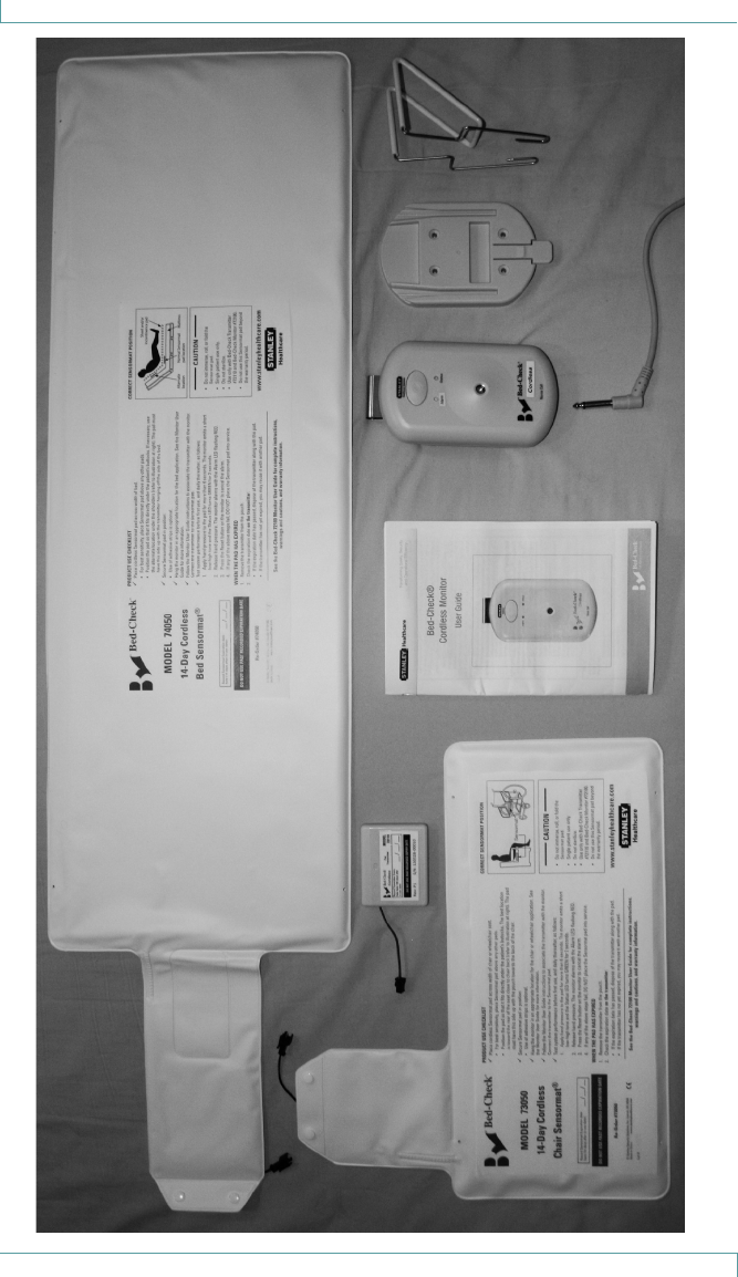
Check Your Shipment
The Bed-Check Fall Management System package includes:
1 – Cordless Monitor (72100)
1 – Wall Mount Bracket (0141-758)
2 – Kits of Dual-Lock® Fasteners (P/N TBD??)
4 – Mounting Screws with Plastic Anchors
1 – Rubber Bumper (0141-757)
1 – Wire Bracket (0120-123)
4 – AA Alkaline Batteries
This Manual (0980-020)
Other Components Sold Separately
Cordless Transmitter (72110)
Cordless Sensormat® pads – available in the following types:
• Chair 14-day (73050)
• Chair 180-day (73060)
• Bed 14-day (74050)
• Bed 180-day (74060)
Additional Wall Mount Brackets (0141-758)
Additional Wire Brackets (0120-123)
Nurse Call Cables (25150)

Introduction
2 Bed-Check® Fall Management System Setup & User Guide
Bed-Check® Fall Management System Monitor Specications
Part Number N/A
Battery Battery Type: Four (4) AA 1.5V
Polarity Protection: Reverse polarity protected
Low Battery Threshold: 4.7V +/- 0.2V
Expected Battery Life: > 1 month with no alarms
Interface Remote Transmitter and pad - RF transmitter
Electrical Monitor - Current consumption in Sleep mode is approx.
30-40 uA.
Dimensions
(W x H x D)
Approx. 8.5 x 14.8 x 4.0 cm (3.4 x 5.70 x 1.65 in)
Weight Monitor - approx. 275 g or 9.70 oz (with batteries)
175 g or 6.17 oz (without batteries)
Operating
Temp.
10 - 50 C
Relative
Humidity
5 - 90 % RH (non-condensing)
Mounting • Wall, chair or bed footboard mountable
• Built-in clip - objects up to 5/16” thick
• Optional wire clip - objects from 5/16” to 2-1/4” thick
Audible
Indicators
“LOW “ Minimum Level = 62dBA - at 1 foot from monitor
“HI” Maximum Level = 96dBA - at 1 foot from monitor
LED Indicators Monitor Alarm LED:
• RED - Pad exit from an on pad monitoring condition.
Monitor Status LED:
• YELLOW - Equipment trouble alerts
• GREEN - Monitoring confirmation
Transmitter Status LED :
• Flashes RED on every pad or on/off state change.
Cordless
Properties
• Monitor and Transmitter- 433.4 MHz
• Range: up to 30 ft (9.14 m) indoors, 350 ft outdoors
• Monitor reliably detects any communication failures with
the pad transmitter within 90 seconds, and then alarms.

How the Bed-Check System Works
Bed-Check® Fall Management System Setup & User Guide 3
How the Bed-Check System Works
When the resident’s weight on the Sensormat pad is removed for a pre-
selected number of seconds (either 0.75 or 2.75 seconds), the Monitor
emits an alarm tone to let staff know that the resident is no longer on the
Sensormat pad, is in an unsafe position, and needs immediate assistance.
A Supervision alarm is an audible alarm that occurs when the resident is on
the pad and:
• Communication with the pad Transmitter being monitored is lost because the
Transmitter has moved out of range or failed, or
• The Transmitter is switched off while monitoring.
The alarm can be cancelled by pressing the button on the monitor.
If a Nurse Call system is connected, the Monitor triggers an alarm similar to
a panic button press on a bedside pendant switch. The staff member, having
been alerted that a resident is attempting to exit the bed, can counsel the
resident by intercom (if available), and send immediate assistance.
Normal Usage Routine
Each time the system is put into use, a specific set of tasks must be
performed to ensure that the system is operating correctly and is effectively
monitoring a resident. Each task listed below refers you, when necessary, to
the section in this guide with the detailed instructions for that task.
Gather the equipment together: Monitor, Transmitter, Pad.
Connect the transmitter to the pad. See “Connecting the Cordless
Transmitter” on page 8.
Activate the monitor and then associate it with the transmitter.
See “Associating the Cordless Monitor with the Transmitter” on
page 10.
Test the system. Follow the test procedure printed on the pad, or
see “Testing the Sensormat Pad Before First Use” on page 11.
Position the resident on the bed or chair.
Press the monitor button to conrm that the system is monitoring
the resident on the pad. Look for the ??second solid green light
on the Status LED.???
When an alarm occurs, follow your facility’s alarm response proce-
dures before resetting the monitor.
To remove the resident from the pad, see “Temporary Disable
Mode” on page 16.
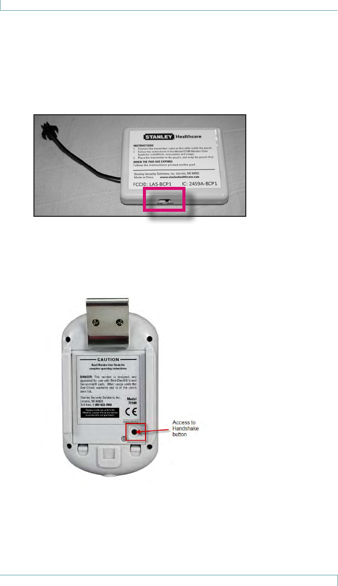
Cordless Monitor
4 Bed-Check® Fall Management System Setup & User Guide
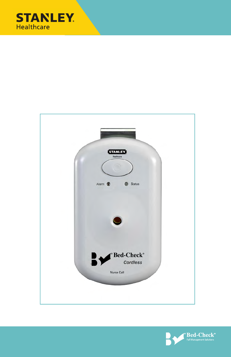
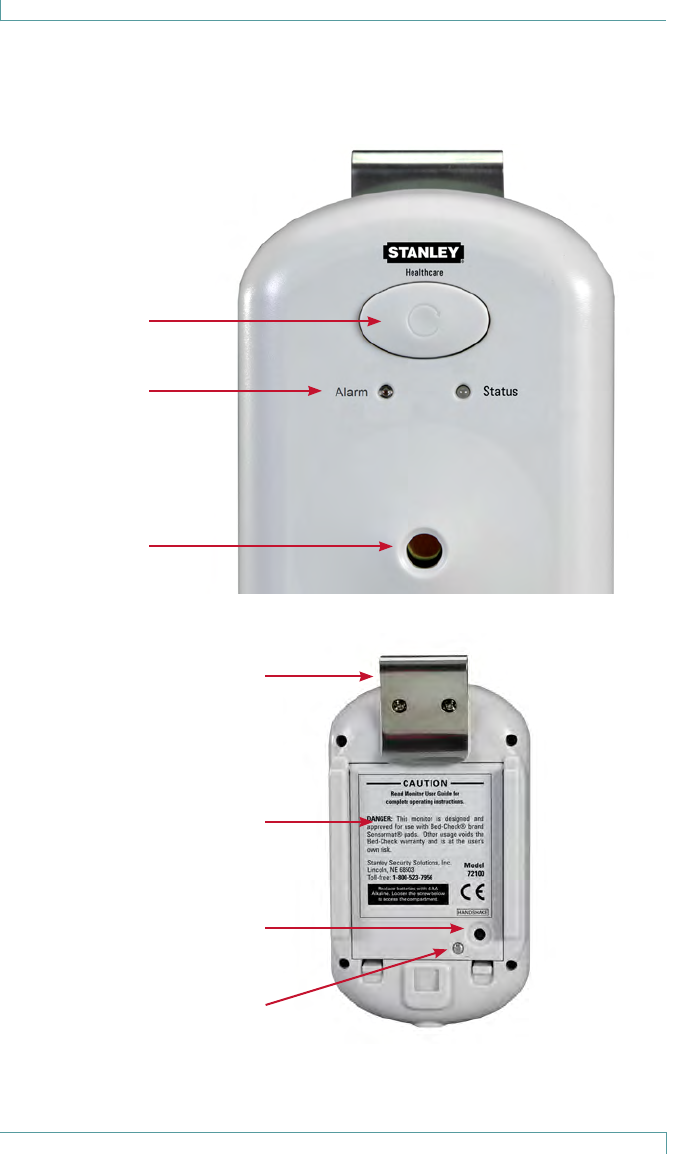
Cordless Monitor
FRONT
BACK
Clip
Battery
Cover
Access to
Handshake
Button
Screw (to open
battery cover)
Alarm Reset
Button
LEDs (Alarm
and Status)
Sound
Opening

Cordless Monitor
Bed-Check® Fall Management System Setup & User Guide 5
Basic Features and Buttons
The Bed-Check Cordless Monitor includes a black rubber bumper around the
outer perimeter. This bumper is not made with natural rubber latex.
The caregiver can tap the button on the front of the Monitor at any time
without disrupting the monitoring session. The Monitor displays its state for
2.4 seconds. When no button is pressed and the Monitor is monitoring a
resident on the pad, the Monitor flashes its GREEN LED once every minute.
State changes are triggered by incoming events such as:
• A short press for less than 3 seconds on the button on the front of the Monitor
• A long press lasting more than 3 seconds on the button on the front of Monitor
• A press of the Handshake button on the back of the Monitor
• Pad on/off status
• Transmitter being switched on or off
• A lack of communication with the Transmitter for 90 seconds
• A change to the Nurse Call jack (plugged or unplugged)
• Low battery status
Alarm Reset Button
The Alarm Reset button is located on the front of the Monitor. All audio alarms
can be muted by a simple tap of the Monitor’s button. The Alarm Reset
button is also used to put the Monitor into Sleep Mode (see “Understanding
LEDs and Audible Tones” on page 7).
Button press timing duration variations are as follows:
• Short tap - less than 3 seconds - used to activate the Monitor, display the
Monitor’s status and cancel any audible alarms.
• Long press - more than 3 seconds - used to either temporarily disable the
monitor (only when monitoring a resident), or put the Monitor to sleep.
Reminder: Tap the Alarm Reset button at any time to check the
monitoring status. Always check the monitoring status
whenever you activate a new Bed-Check monitoring
session, or place a resident on the pad.
RED Alarm LED
The left-most LED is bright RED, and is only used to signify that an
unexpected pad exit has occurred, the resident is at risk of falling, and
immediate caregiver response is required.
The alarm LED is easily seen from a distance of 4 m from the Monitor in
normal facility lighting conditions as long as no direct sunlight is falling on the
Monitor.

Cordless Monitor
6 Bed-Check® Fall Management System Setup & User Guide
Bi-Color Status LED
This LED indicates Monitor and pad Transmitter status.
Generally:
• GREEN indicates successful communication with a pad Transmitter and, if
repeated once per minute with a flash lasting half a second or more, that there is
a resident being monitored on the pad
• YELLOW indicates equipment trouble, including low battery or supervision alarms
when communication are lost. YELLOW accompanied by the trouble tone
indicates a problem that prevents monitoring a resident on the pad.
LED use during normal conditions is minimized to help extend the Monitor’s
battery life.
Sound Opening
The sound opening allows the alarm to be annunciated from the Monitor.
Clip
Use the clip to attach the Monitor to a wheelchair.
Battery Cover
The battery cover is used to protect the batteries and the settings area
(Volume, Tone, etc.). For information about changing the batteries, see
“Replacing Batteries” on page 17.
Reminder: Check that the battery screw is tightened to avoid batteries
accidentally falling out if the Monitor is dropped.
Handshake Button
For information about the Handshake button, see “Associating the
Cordless Monitor with the Transmitter” on page 10.

Cordless Monitor
Bed-Check® Fall Management System Setup & User Guide 7
Understanding LEDs and Audible Tones
The following table explains the basic LED colors and tones. For more
detailed information about other available Monitor states, see “Regulatory
Compliance” on page 27.
Alarm LED
The Alarm LED flashes RED only, indicating an unexpected pad exit has
occurred and a resident is now in imminent danger of falling.
Status LED
The Status LED flashes GREEN or YELLOW, indicating either normal
operation or an issue with the equipment.
Refer to the table below for a description of the Alarm and Status LEDs.
LED Tone Description
ALARM LED (RED)
Flashes once every
0.6 seconds
Alarm Alarm!
• Resident has left bed/chair!
One long ash High-Low • Monitor placed into Sleep Mode
STATUS LED (GREEN/YELLOW)
GREEN – short ash
(0.1 second) only on
button press
No • Monitor is communicating with
transmitter
GREEN - long ash
(> 0.5 seconds),
once per minute or
on button press
No • Resident being monitored on the pad
GREEN – two long
ashes
Low-High • Successful association of Monitor with
Transmitter (Handshake)
GREEN – 5 second
rapid ash
No • Transition from “off pad ready” to “on
pad monitoring” when resident moves
onto pad
GREEN – extended
countdown ash
No • Monitor temporarily disabled to allow
resident positioning or removal
YELLOW – Five 0.1
second ashes
repeated every 2.4
seconds
Trouble Warning
• Supervision failure
• Monitor battery failure
• Equipment error
Cordless Monitor
8 Bed-Check® Fall Management System Setup & User Guide
LED Tone Description
YELLOW – Two 0.1
second ashes, once
per minute
Low Warning
• Transmitter low battery
YELLOW –
continuous up to 10
seconds
No • Waiting for association Handshake
YELLOW –
continuous
No • Failed monitor power-up self-test or
monitor battery dying.
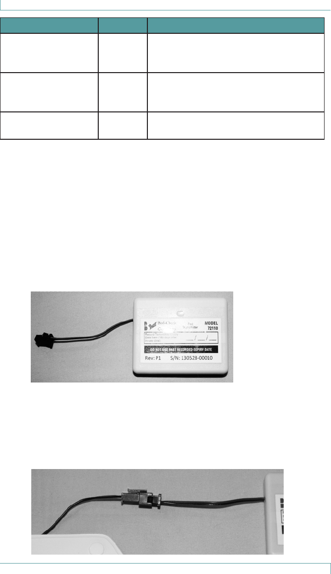
Cordless Transmitter
The Cordless Transmitter has one LED that flashes RED when it is turned
on or off, and on every pad on/off state change. It must be plugged into the
Sensormat Pad to function.
There is an ON/OFF switch located on the side of the Cordless Transmitter.
Up to 20 Transmitters may be deployed within 30 feet of any one monitor
without interference between them.
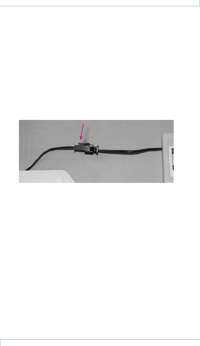
Connecting the Cordless Transmitter
1. On rst use, record the expiry date (180 days from in-use date) on the
Transmitter. At every other use, check the expiry date before connecting.
2. Connect the Transmitter cable to the cable inside the pouch (located on
the Sensormat Pad). The connectors are keyed to permit only one
orientation. Insert the Transmitter end of the connector into the pad end
until you feel the “click” indicating a successful connection.

Cordless Monitor
Bed-Check® Fall Management System Setup & User Guide 9
3. See “Associating the Cordless Monitor with the Transmitter” on page
10 to associate the Transmitter with the Cordless Monitor.
4. Once the Transmitter is associated with the Cordless Monitor, place the
Transmitter in the pouch, and snap the pouch shut.
Removing the Cordless Transmitter from the Pad
1. Open the pouch snaps.
2. Slide the Transmitter from the pouch.
3. Switch o the Transmitter if it is not to be used for an extended period
of time.
4. Squeeze the latch to detach the connectors.
Confirming Battery State and Usage
If either 6 months has passed since the Transmitter was first activated, or the
Monitor warns that the Transmitter has a low battery, the Transmitter should
no longer be used.
Cleaning the Cordless Transmitter
Clean with a damp wipe only. Do not sterilize. Do not immerse. Ensure that
the Transmitter is dry before placing in storage.
Disposing of the Cordless Transmitter
The Cordless Transmitter contains Lithium Manganese Dioxide battery cells.
Dispose according to local regulations.
Cordless Monitor
10 Bed-Check® Fall Management System Setup & User Guide
Associating the Cordless Monitor with
the Transmitter
Follow these steps to associate the Monitor with the Transmitter.
1. Ensure the Transmitter switch is in the “O” position, and wait at least 5
seconds.
2. Make sure the monitor is on by tapping the button on the front. The
Status LED ashes YELLOW.
3. Press the “Handshake” button on the back of the Monitor through the
access hole in the battery cover using a pointed object such as a stylus.
4. Within 8 seconds:
4.1 Switch the Transmitter “ON.” A pen tip or stylus may be useful.
A Handshake message is sent to the Monitor to associate the
Transmitter with the Monitor.

Cordless Monitor
Bed-Check® Fall Management System Setup & User Guide 11
4.2 While waiting for the Handshake message, the LED on the Monitor
glows YELLOW.
4.3 While transmitting the Handshake message, the Transmitter’s
internal LED ashes RED.
4.4 The Monitor beeps twice (low then high), and the LED ashes
GREEN twice, indicating a successful association of the Transmitter
with the Monitor.
Note: If 10 seconds passes after the Handshake button is pressed
and no Handshake message is detected by the Monitor, the
Status LED flashes YELLOW 5 times while the Monitor looks for
the last Transmitter it was associated with. If the transmitter is
not found, switch the transmitter Off, wait at least 5 seconds,
then repeat from Step 1.
4.5 Test for a successful association by pressing the Monitor button
once. The Status LED should ash GREEN.
5. Connect the Transmitter to the Sensormat pad according to the
instructions in “Connecting the Cordless Transmitter” on page 8.
6. Place the Transmitter in the pouch and snap it closed.
Testing the Sensormat Pad Before First Use
Test the Sensormat Pad before first use, and daily thereafter, as follows:
1. Apply hand pressure to the Pad for more than 6 seconds. The Monitor
emits a short low-high tone and the Status LED turns GREEN for two
seconds.
2. Release hand pressure. The Monitor alarms and the Alarm LED ashes
RED.
3. Press the Reset button on the Monitor to cancel the alarm.
4. If any of the above steps fail, check all conections, and try re-associating
the transmitter. If it still does not work, DO NOT place the pad into
service.
Note: The Monitor remembers the Transmitter it is associated
with, even when the Monitor’s batteries are removed or the
transmitter is switched off.
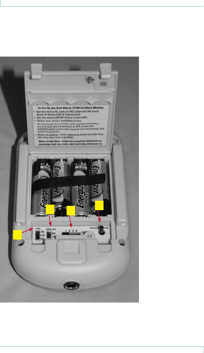
Configuring the Cordless Monitor
12 Bed-Check® Fall Management System Setup & User Guide
Configuring the Cordless Monitor
This section describes how to change settings for the Bed-Check Cordless
Monitor. Unscrew, then pressing the clips, lift the bottom of the cover to
expose the settings switches.
A
BCD

Configuring the Cordless Monitor
Bed-Check® Fall Management System Setup & User Guide 13
A. Vol - Volume for the alarm and trouble tones - 3 settings:
• HI - Raises the audible tone to the loudest level.
• LO - Lowers the audible tone to the softest level.
• NC - Nurse Call - If a Nurse Call jack is plugged in and this
setting is selected, the local alarm sound is suppressed
completely.
Note: If the NC setting is selected but there is no Nurse Call cord
plugged in, a local alarm (HI) is annunciated through the Monitor
if the resident leaves the pad.
B. DELAY - The time delay (in seconds) before the alarm is annunciated - 2
settings:
• 0S (zero seconds) - up to 0.75 seconds, no additional delay
• 2S (two seconds) - up to 0.75 seconds, plus 2 additional seconds
C. TONE - Tone sequences for the audible alarm or trouble condition- 4
settings. See “Audible Tones” on page 14.
D. HANDSHAKE - This button is used to establish an association between
the Transmitter and the Monitor.

Audible Tones
14 Bed-Check® Fall Management System Setup & User Guide
Audible Tones
There are three sets of audible tones that are used with the Cordless Monitor:
• Alarm Tones
• Trouble Tones
• Confirmation Tones
Note: The exact sound of the alarm or trouble tones depends on the
TONE switch setting and whether the current state is an alarm
relating to an unexpected pad exit) or a trouble tone relating
to a hardware problem (e.g., supervision alarm). Confirmation
tones are not affected by these settings.
Alarm Tones
There are 4 alarm tone sequences associated with the Alarm LED (flashes
RED):
• 1 - One sound (low) in a sequence of 3 beeps, pause, 2 beeps
(meets UL 60601-1)
• 2 - Two sounds (low high low high) in a sequence of 4 beeps, pause, 2 beeps
• 3 - Two sounds (low high low) in a sequence of 3 beeps, pause, 2 beeps
• 4 - Two sounds (high low high) in a sequence of 3 beeps, pause, 2 beeps
Trouble Tones
There are 4 trouble tone sequences associated with the Status LED (flashes
YELLOW):
• 1 - One sound (low) in a sequence of 3 beeps (meets UL 60601-1)
• 2 - Two sounds (low high low high) in a sequence of 4 beeps
• 3 - Two sounds (low high low) in a sequence of 3 beeps
• 4 - Two sounds (high low high) in a sequence of 3 beeps

Sleep Mode
Bed-Check® Fall Management System Setup & User Guide 15
Sleep Mode
The Bed-Check Monitor supports a Sleep Mode feature to save battery life
while not in use.
Automatic Sleep Mode
The Monitor enters Sleep Mode under either of the following conditions:
• After 24 hours with no resident on the pad
• After 10 minutes with no associated transmitter
To Manually Put the Monitor to Sleep
Follow these instructions to turn Sleep Mode on when the Monitor is not in
use. The Monitor cannot be placed in Sleep Mode while it is monitoring a
resident.
1. Make sure that the Monitor is not monitoring a resident on the pad.
2. Press and hold the Alarm Reset button for at least 3 seconds.
3. The Status LED changes to a solid RED and the Monitor beeps high, then
low once. The Monitor has entered Sleep Mode.
Wake the Monitor from Sleep Mode
Follow these instructions to turn Sleep Mode off.
1. Press the Alarm Reset button once to exit Sleep Mode.
2. The Status LED ashes YELLOW or GREEN.
3. Sleep Mode is now turned o.

Temporary Disable Mode
16 Bed-Check® Fall Management System Setup & User Guide
Temporary Disable Mode
The temporary disable mode is used to allow the caregiver 2 minutes to
remove a resident from a monitored pad without triggering any alarms, or to
connect or disconnect the Nurse Call cord.
1. Press the Alarm Reset button on the Monitor for more than 3 seconds.
2. A 2 minute timer is set. The Status LED ashes GREEN until the time
expires, before the Monitor resumes monitoring the resident. A single
ash sequence indicates that less than 1 minute remains.
3. The resident can now be placed on, or removed from the pad, or the
Nurse Call cord may be inserted or removed without triggering an
alarm.
4. When the timer runs out, or the button is pressed for less than 3
seconds, the Monitor resumes normal operation. If the resident is still o
the pad, or the Nurse Call cord has been inserted or removed, no alarm
is generated.
Low Battery States
Monitor Low Battery
The Monitor’s batteries will last at least 30 days while monitoring a person on
a pad.
When the Monitor batteries are low – approximately within 3 days of depletion
– the Status LED flashes a YELLOW warning (with a confirmation tone).
• If the resident is on the pad, the YELLOW flash follows the GREEN on-
pad confirmation flash, once per minute.
• If the resident is not on the pad, a single YELLOW flash occurs once per
minute.
These sequences repeat until the batteries are replaced.
When the low battery warning level has been reached, no new monitoring
sessions can be started until the batteries are replaced.
When the Monitor determines that its batteries are within minutes of
depletion, the audible alarm sounds, and the monitor stops functioning.
Note: Monitors may deplete new batteries when kept in continuous
sleep mode for more than 2 years.

Temporary Disable Mode
Bed-Check® Fall Management System Setup & User Guide 17
Transmitter Low Battery
When the battery is low (about 20 days before depletion) in the Transmitter,
the Monitor’s Status LED flashes a YELLOW warning twice (with a
confirmation tone).
• If the resident is on the pad, the YELLOW flashes follow the GREEN on-
pad confirmation flash, once per minute.
• If the resident is not on the pad, the YELLOW flashes occur once per
minute.
These sequences repeat until the Transmitter is replaced. If the Transmitter
battery fails while the pad is monitoring a resident, a supervision alarm is
generated.
A Transmitter can be confirmed to be working without using a Monitor by
checking if its LED flashes when a resident goes on or off the pad, or the
transmitter itself is turned on or off.
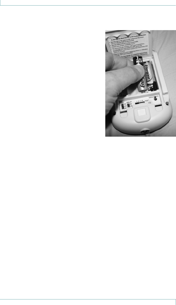
Replacing Batteries
To remove the batteries
1. Open the battery compartment cover.
2. Gently pull the black ribbon vertically to release the batteries.
IMPORTANT: Dispose of batteries according to your local environmental laws
and guidelines.
Temporary Disable Mode
18 Bed-Check® Fall Management System Setup & User Guide
To insert the batteries
1. Loosen screw to open the battery
compartment cover.
2. Remove used batteries if required.
3. Ensure the black ribbon is laying at
along the bottom.
4. Insert the batteries into the battery
compartment. Press the negative
end of each battery into the
corresponding spring, then slide the
positive end into the contact. The
monitor immediately performs a self-
test. The LEDs ash in all colors and
the speaker sounds.
5. Close the battery compartment cover.
6. The Monitor is now ready to be associated with a Transmitter and used
for a resident.
CAUTION: Replace all four batteries at the same time. Do not mix
old batteries with new batteries, and do not mix battery
types. Only non-rechargeable alkaline batteries are
UL-compliant and meet the product specication. AA
batteries equivalent to Duracell MN1500 or Energizer
LR06 are recommended.

Using Sensormat Pads
Bed-Check® Fall Management System Setup & User Guide 19
Using Sensormat Pads
The Sensormat pad can be located either on a bed or chair, directly
underneath the resident. The Monitor is mounted on the wall outside of the
room, or in another convenient location, no more than 30 feet away from the
pad; or attached to a wheelchair. 14-day or 180-day pads can be deployed
with the Monitor. These pads should be replaced on or before their
warranty period expiry date (indicated on pad).
On a Bed
Place the Sensormat pad across the width of the bed, ON TOP OF THE
MATTRESS. A top sheet and/or incontinence pad may be placed above the
Sensormat pad. The preferred pad location is directly under the resident’s
buttocks three to five inches below the bend in the mattress when the
head of the bed is elevated. Effective operation of the Sensormat pad in
the alternative location, behind the resident’s back, is dependent upon their
weight and the articulation angle of the bed.
The use of anti-skid strips to secure the Sensormat pad to the mattress is
optional.
On a Chair
Place the Sensormat pad across the width of the chair or wheelchair seat.
For best sensitivity, place the Sensormat pad above any other pads. An
incontinence pad may be placed above the Sensormat pad. Adjust the
position so that it fits directly under the resident’s buttocks. The most
favorable location is toward the rear of the seat, close to the chair back.
The use of anti-skid strips to secure the Sensormat pad to the seat of the
chair is optional.
Note: Once the resident sits on the pad, there is a 6 to 7 second
delay, before the Monitor arms, allowing time for the resident to
shift around slightly until a comfortable position is achieved.

Changing the Pad Transmitter
20 Bed-Check® Fall Management System Setup & User Guide
Changing the Pad Transmitter
The Pad Transmitter has a usable life of 180 days from first activation.
The Monitor can be associated with only one Pad Transmitter at a time.
When you change the Pad Transmitter, you must establish a new association
between the Pad Transmitter and the Monitor.
Follow these steps to change the Pad Transmitter.
1. Remove the Monitor from the wall or unclip it from a chair or bed
footboard so that you can access the back of the monitor.
2. Bring the monitor and the Pad Transmitter together.
3. Turn the Pad Transmitter o using the slide switch and a pen tip, then
wait at least 5 seconds.
4. Ensure the monitor is awake by tapping the front button.
5. Depress the Handshake button on the back of the monitor.
6. Within 5 seconds, switch on the Pad Transmitter.
7. The monitor Status LED should ash GREEN and you should hear a low-
high conrmation tone. If not, repeat from step 3.
8. You are now ready to monitor the resident.
Changing the Sensormat Pad
Bed-Check® Fall Management System Setup & User Guide 21
Changing the Sensormat Pad
When you change the Sensormat pad, the Pad Transmitter may be reused
until its expiry date or low battery condition has been reached.
Follow these steps to change the Sensormat.
1. If monitoring a resident on a pad rst temporarily disable the monitor and
remove the resident.
2. Remove the old pad from the bed or chair.
3. Open the pouch on the old pad.
4. Remove the Pad Transmitter from the old pad and disconnect it by
depressing the latch mechanism.
5. After examining the transmitter expiry date, If you need to replace it,
refer to “Changing the Pad Transmitter” on page 20.
6. Connect the Pad Transmitter to the new pad and then insert into the
pouch, closing and fastening the pouch ap.
7. Tap the monitor to activate monitoring.
8. Conrm the proper operation of the pad as described on the pad.

Mounting/Installation Options
22 Bed-Check® Fall Management System Setup & User Guide
Mounting/Installation Options
The Bed-Check Cordless Monitor may be mounted on a wall, a bed
footboard, or a chair.
CAUTION: Do not place the monitor within 1 ft. (0.3m) of and facing
the resident. Placing the monitor on a wheelchair back
is acceptable as long as the monitor is facing away from
the resident.
Wall Mounting
To mount the Bed-Check Cordless Monitor on a wall, you will need a Wall
Mount Bracket (0141-758). The mounting bracket is installed with the
included screws or Dual-Lock® fastener.
If you are using a Nurse Call system, you will also need a Nurse Call Cable
(25150). Before mounting the wall bracket, refer to “Mounting/Installation
Options” on page 22 for details.
1. Attach the Wall Mount Bracket to a vertical surface using the provided
screws or Dual-Lock fasteners. If also installing a Nurse Call cable or
attaching to a surface that is not at and smooth, use the screws to
secure the bracket rmly in place. On at and smooth surfaces, the Dual-
Lock fastener may be used to allow for easier removal.
2. Install the bracket on the wall when monitoring persons in bed.
3. To attach the Bed-Check Monitor on the bracket, slide the Monitor down
into the bracket from the top until the release button clicks.
4. Insert the Nurse Call cable jack into the Nurse Call receptacle. Plug the
other end into the installed nurse call system.
5. Test the monitoring system. Refer to “Testing the Sensormat Pad Before
First Use” on page 11.
Mounting/Installation Options
Bed-Check® Fall Management System Setup & User Guide 23
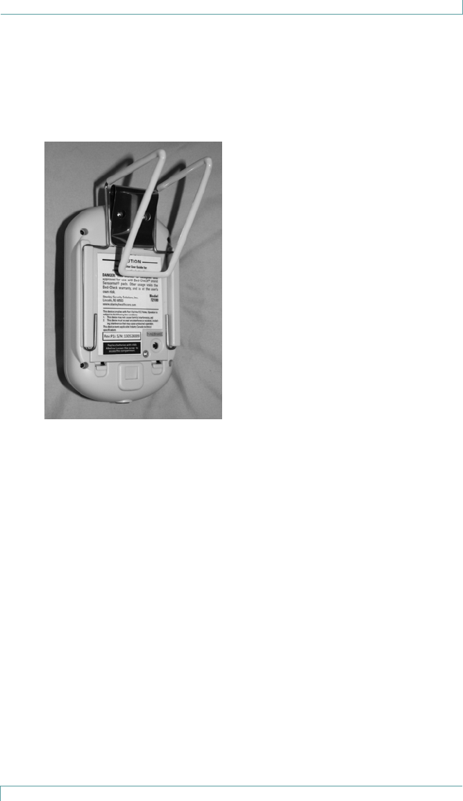
Chair or Bed Footboard Mounting
To mount the Bed-Check Cordless Monitor on a chair or on a bed footboard,
you will need a Wire Bracket (0120-123).
1. Slide the Wire Bracket into the slots on the back of the Monitor as
shown here.
2. Use the clip to attach the Monitor securely to the back of the chair, in a
place that the resident cannot easily reach.
3. Ensure that the Monitor is clipped to the outside of the chair to reduce
any discomfort for the resident.
Interfacing with a Nurse Call System
24 Bed-Check® Fall Management System Setup & User Guide
Interfacing with a Nurse Call System
The Bed-Check Monitor can be used to trigger a Nurse Call system that
works with call button circuits that are normally open, closing only when
the call button is depressed. Normally closed Nurse Call systems are not
supported.
The Monitor accepts a common ¼” mono plug that can be wired to a Nurse
Call system. The monitor will alarm if a Nurse Call jack is inserted or removed
while monitoring a patient on the pad. If the Nurse Call jack needs to be
adjusted while a patient is on the pad use the “Temporary Disable Mode”
to allow this. When installing a Nurse Call jack, we recommend using the
wall mount bracket in the manner shown, which provides cable restraint to
help prevent accidental unplugging of the jack. Note that the cable must be
inserted before the bracket is mounted on the wall.
If your nurse call system does not provide a compatible input or if you want to
wire a push button cord in parallel with the monitor, contact your biomedical
department to obtain the appropriate adapter. The monitor does not have an
input to allow a push button to be wired in parallel.
If requesting information on interfacing the Monitor to a nurse call system,
please have the following information available:
• The brand of your nurse call system.
• A description of the system’s call cord or pillow speaker, including the
type of plug and number of pins in the plug.
• Whether your nurse call system is normally open or normally closed.
If this information is not available, you may still contact us for assistance, and
we will be glad to help you.

Interfacing with a Nurse Call System
Bed-Check® Fall Management System Setup & User Guide 25
Nurse Call Alarms
With a Nurse Call cable plugged in, the Monitor calls the Nurse Call system
continuously during a pad exit alarm, supervision warning, or imminent
battery failure. However, low battery warnings are not sent.
The Nurse Call jack can be used in all 3 audio volume settings (HI, LO and
NC). When a Nurse Call jack is plugged in and the monitor’s alarm volume is
set to “NC”, all local alarms except Nurse Call jack-related alarms are muted
on the monitor. The “NC” volume setting is ignored if no Nurse Call jack is
plugged in.
Note: An alarm sent to the Nurse Call system cannot be cancelled from the
Monitor alone. After dealing with the resident according to your care policy,
the alarm must first be cancelled on the monitor, and then at the Nurse Call
system. Refer to the Nurse Call system user guide for details on cancelling
alarms at the Nurse Call station.
The Monitor also alarms audibly when the Nurse Call jack is plugged in or
unplugged while the resident is on the pad. To connect or disconnect the
Nurse Call jack while the resident is on the pad, you must temporarily disable
the monitor.

Maintenance
26 Bed-Check® Fall Management System Setup & User Guide
Maintenance
The Monitor and the Sensormat pad may be cleaned with a damp cloth
or sponge using mild disinfectants. Never use alcohol, acidic or harsh
petroleum-based cleaners.
The Monitor tolerates all EtO (ethylene oxide) gas sterilization processes
below 70 degrees C. Other types of gas sterilization are NOT to be used on
the Monitor (e.g., formaldehyde, chlorine or hydrogen peroxide). Do NOT
sterilize the Sensormat pad.
Note: Remove the rubber bumper before sterilization to ensure that
the entire monitor surface is sterilized.
To ensure maximum performance, follow these guidelines:
• Replace the Sensormat mat every 14 or 180 days, depending on the
pad type. Note: The Sensormat Pad is for single resident use only.
• If maintenance or opening of the Monitor is required, it should be
performed in a static-free environment by qualified personnel.
• Replace the batteries in the Monitor upon low battery signal.
• Perform regular status checks on Monitors (status and connection). See
Status Checks below.
Status Checks
Perform the following checks, on Monitors and Sensormat pads, on a regular
basis (according to your facility policy):
1. Apply hand pressure to the Sensormat pad and maintain pressure for
about 6 seconds. The Monitor should beep once, and the Status LED
should ash GREEN every two seconds.
2. Release hand pressure. The Monitor should sound an alarm.
3. Press the Reset button on the Monitor to silence the alarm.
4. If the Monitor did not signal an alarm, do not place the Sensormat pad
into service.
5. Repeat this test using a new Sensormat pad to conrm that both the
Monitor and Sensormat pad are working before putting them into
service.
6. If the Monitor is used with a nurse call system, verify that the remote
alarm also sounded during the test.

Regulatory Compliance
Bed-Check® Fall Management System Setup & User Guide 27
Regulatory Compliance
FCC
47 CFR Part 15, Class B Device
This device complies with part 15 of the FCC Rules. Operation is subject
to the following two conditions: (1) This device may not cause harmful
interference, and (2) this device must accept any interference received,
including interference that may cause undesired operation.
Changes or modifications not expressly approved by the party responsible for
compliance could void the user’s authority to operate the equipment.
Industry Canada
This device complies with Industry Canada licence-exempt RSS standard(s).
Operation is subject to the following two conditions: (1) this device may not
cause interference, and (2) this device must accept any interference, including
interference that may cause undesired operation of the device.
Le présent appareil est conforme aux CNR d’Industrie Canada applicables
aux appareils radio exempts de licence. L’exploitation est autorisée aux deux
conditions suivantes : (1) l’appareil ne doit pas produire de brouillage, et (2)
l’utilisateur de l’appareil doit accepter tout brouillage radioélectrique subi,
même si le brouillage est susceptible d’en compromettre le fonctionnement.
IEC/UL
Conforms with IEC/UL 60601-1 3rd Edition. This device was tested to
conform with IEC/UL 60601-1 3rd Edition by a third party assessment
completed by Nemko.
RoHS
RoHS Directive – 2002/95/EC

Warranty Information
28 Bed-Check® Fall Management System Setup & User Guide
Warranty Information
LIMITED WARRANTY:
BED-CHECK® CONTROL UNITS
1. WARRANTOR:
This Limited Warranty is given by STANLEY Healthcare, 130 Turner Street, Waltham, MA 02453.
2. DURATION:
This Limited Warranty begins on the date the product is delivered to the purchaser and continues for a period of two years (new units) or
one year (refurbished units).
3. TO WHOM THIS LIMITED WARRANTY IS GIVEN:
This Limited Warranty is given to the original purchaser of Bed-Check’s products only.
4. PRODUCTS COVERED:
This Limited Warranty covers all Bed-Check Control Units. (i.e., Bed-Check Cordless, Model Vr, Classic-Check, Chair-Check II, and
Basic-Check)
5. WHAT IS COVERED UNDER THIS LIMITED WARRANTY:
Defects in material and workmanship which occur within the defined duration of this limited warranty. Warrantor makes no other war-
ranties expressed or implied, including without limitation, warrantor makes no warranty as to merchantability or fitness for a particular
purpose.
6. WHAT IS NOT COVERED UNDER THIS LIMITED WARRANTY:
a) ANY INCIDENTAL, INDIRECT, OR CONSEQUENTIAL LOSS, DAMAGE, OR EXPENSE THAT MAY RESULT FROM ANY
DEFECT, FAILURE, OR MALFUNCTION OF THE CONTROL UNITS.
b) ANY INCIDENTAL, INDIRECT, OR CONSEQUENTIAL LOSS, DAMAGE, OR EXPENSE THAT MAY RESULT FROM USE OF
THE CONTROL UNITS WITH ANOTHER MANUFACTURER’S PRESSURE SENSITIVE MAT, SENSING DEVICE, OR OTHER
FALL PREVENTION PRODUCT.
NOTE: SOME STATES DO NOT ALLOW THE EXCLUSION OR LIMITATION OF INCIDENTAL OR
CONSEQUENTIAL DAMAGES, SO THE ABOVE LIMITATIONS OR EXCLUSIONS MAY NOT APPLY TO
YOU.
c) Any defects or damage to the Control Units that may result from use of the Control Units with another manufacturer’s parts, pressure
sensitive mat, sensing device, or other fall prevention product.
d) Any failure that results from an accident, purchaser’s abuse, neglect or failure to operate the Control Units in accordance with the
instructions provided in the owner’s manual(s) supplied with the Control Units.
e) Any Control Units which have the serial numbers altered, defaced or removed.
f) Any Control Units which have been altered or modified in any way without the express written consent of Bed-Check.
g) Any Control Units which have been repaired other than by Bed-Check.
7. RESPONSIBILITIES OF WARRANTOR UNDER THIS LIMITED WARRANTY:
a) In the event of a defect, malfunction, or other failure of the product not caused by any misuse or damage to the product while in the
possession of purchaser, the warrantor will remedy the failure or defect without charge to the purchaser within a reasonable time. The
remedy will consist of repair or replacement of the product, or refund of the purchase price, at the warrantor’s option. If the product is no
longer available, warrantor will supply purchaser with a comparable product or refund the purchase price at warrantor’s option. However,
the warrantor will not elect refund unless it is unable to provide replacement, and repair is not commercially practicable and cannot be
made within a reasonable time, or unless the purchaser is willing to accept such refund.
b) If this product or one of its component parts contains a defect or malfunction, after a reasonable number of attempts by the warrantor
to remedy the defects or malfunctions, the purchaser will be entitled to either a refund or replacement of the product or its component
part or parts. Replacement of a component part includes its free installation.
8. RESPONSIBILITIES OF THE PURCHASER UNDER THIS LIMITED WARRANTY:
a) Disinfect the Control Unit, if necessary, so that it is reasonably free from infectious matter.
b) Package the Control Unit with a minimum of two inches of shock absorbent packaging material.
Deliver or ship the Control Unit to:
STANLEY Healthcare, 130 Turner Street, Waltham, MA 02453. Freight costs, if any, must be borne by the purchaser.
c) Use the Control Unit with reasonable care and in accordance with the supplied owner’s manual.
THIS LIMITED WARRANTY GIVES YOU SPECIFIC LEGAL RIGHTS AND YOU MAY ALSO HAVE
OTHER RIGHTS WHICH VARY FROM STATE TO STATE.

Warranty Information
Bed-Check® Fall Management System Setup & User Guide 29
LIMITED WARRANTY:
BED-CHECK® SENSORMATS®
1. WARRANTOR:
This Limited Warranty is given by STANLEY Healthcare, 130 Turner Street, Waltham, MA 02453.
2. DURATION:
This Limited Warranty begins on the date the product is delivered to the purchaser and continues for a period of one year or for the dura-
tion of the warranty stated on the Sensormat label from the date first installed, whichever comes first.
3. TO WHOM THIS LIMITED WARRANTY IS GIVEN:
This Limited Warranty is given to the original purchaser of Bed-Check’s products only.
4. PRODUCTS COVERED:
This Limited Warranty covers all Bed-Check Sensormats.
5. WHAT IS COVERED UNDER THIS LIMITED WARRANTY:
Defects in material and workmanship which occur within the period described in paragraph 2. Warrantor makes no other warranties
expressed or implied, including without limitation, warrantor makes no warranty as to merchantability or fitness for a particular purpose.
6. WHAT IS NOT COVERED UNDER THIS LIMITED WARRANTY:
a) ANY INCIDENTAL, INDIRECT, OR CONSEQUENTIAL LOSS, DAMAGE, OR EXPENSE THAT MAY RESULT FROM ANY
DEFECT, FAILURE, OR MALFUNCTION OF THE SENSORMAT ANY INCIDENTAL, INDIRECT, OR CONSEQUENTIAL LOSS,
DAMAGE, OR EXPENSE THAT MAY RESULT FROM USE OF THE SENSORMAT WITH ANOTHER MANUFACTURER’S
CONTROL UNIT OR OTHER FALL PREVENTION PRODUCT.
NOTE: SOME STATES DO NOT ALLOW THE EXCLUSION OR LIMITATION OF INCIDENTAL OR
CONSEQUENTIAL DAMAGES, SO THE ABOVE LIMITATIONS OR EXCLUSIONS MAY NOT APPLY TO
YOU.
b) Any defects or damage to the Sensormat that may result from use of the Sensormat with another manufacturer’s parts, control unit, or
other fall prevention product.
c) Any failure that results from an accident, purchaser’s abuse, neglect or failure to operate the Sensormat in accordance with the instruc-
tions provided on the Sensormat label.
d) Any Sensormat which has the serial numbers altered, defaced or removed.
e) Any Sensormat which has been altered or modified in any way without the express written consent of Bed-Check.
f) Any Sensormat which has been repaired other than by Bed-Check.
7. RESPONSIBILITIES OF WARRANTOR UNDER THIS LIMITED WARRANTY:
a) In the event of a defect, malfunction, or other failure of the product not caused by any misuse or damage to the product while in the
possession of purchaser, the warrantor will remedy the failure or defect without charge to the purchaser within a reasonable time. The
remedy will consist of repair or replacement of the product, or refund of the purchase price, at the warrantor’s option. If the product is no
longer available, warrantor will supply purchaser with a comparable product or refund the purchase price at warrantor’s option. However,
the warrantor will not elect refund unless it is unable to provide replacement, and repair is not commercially practicable and cannot be
made within a reasonable time, or unless the purchaser is willing to accept such refund.
b) If this product or one of its component parts contains a defect or malfunction, after a reasonable number of attempts by the warrantor
to remedy the defects or malfunctions, the purchaser will be entitled to either a refund or replacement of the product or its component
part or parts. Replacement of a component part includes its free installation.
8. RESPONSIBILITIES OF THE PURCHASER UNDER THIS LIMITED WARRANTY:
a) Disinfect the Sensormat, if necessary, so that it is reasonably free from infectious matter.
b) Package the Sensormat unfolded and in a flat position. Deliver or ship the Sensormat to
STANLEY Healthcare, 130 Turner Street, Waltham, MA 02453. Freight costs, if any, must be borne by the purchaser.
c) Use the Sensormat with reasonable care and in accordance with the supplied owner’s manual.
THIS LIMITED WARRANTY GIVES YOU SPECIFIC LEGAL RIGHTS AND YOU MAY ALSO HAVE
OTHER RIGHTS WHICH VARY FROM STATE TO STATE.

Warranty Information
30 Bed-Check® Fall Management System Setup & User Guide
LIMITED WARRANTY:
BED-CHECK® CORDLESS TRANSMITTERS
1. WARRANTOR:
This Limited Warranty is given by STANLEY Healthcare, 130 Turner Street, Waltham, MA 02453.
2. DURATION:
This Limited Warranty begins on the date the product is delivered to the purchaser and continues for a period of one year, or for 180
days from the date first installed, whichever comes first.
3. TO WHOM THIS LIMITED WARRANTY IS GIVEN:
This Limited Warranty is given to the original purchaser of Bed-Check’s products only.
4. PRODUCTS COVERED:
This Limited Warranty covers all Bed-Check Cordless Transmitters.
5. WHAT IS COVERED UNDER THIS LIMITED WARRANTY:
Defects in material and workmanship which occur within the period described in paragraph 2. Warrantor makes no other warranties
expressed or implied, including without limitation, warrantor makes no warranty as to merchantability or fitness for a particular purpose.
6. WHAT IS NOT COVERED UNDER THIS LIMITED WARRANTY:
a) ANY INCIDENTAL, INDIRECT, OR CONSEQUENTIAL LOSS, DAMAGE, OR EXPENSE THAT MAY RESULT FROM ANY
DEFECT, FAILURE, OR MALFUNCTION OF THE CORDLESS TRANSMITTER ANY INCIDENTAL, INDIRECT, OR
CONSEQUENTIAL LOSS, DAMAGE, OR EXPENSE THAT MAY RESULT FROM USE OF THE CORDLESS TRANSMITTER
WITH ANOTHER MANUFACTURER’S CONTROL UNIT OR OTHER FALL PREVENTION PRODUCT.
NOTE: SOME STATES DO NOT ALLOW THE EXCLUSION OR LIMITATION OF INCIDENTAL OR
CONSEQUENTIAL DAMAGES, SO THE ABOVE LIMITATIONS OR EXCLUSIONS MAY NOT APPLY TO
YOU.
b) Any defects or damage to the Cordless Transmitter that may result from use of the Cordless Transmitter with another manufacturer’s
parts, control unit, or other fall prevention product.
c) Any failure that results from an accident, purchaser’s abuse, neglect or failure to operate the Cordless Transmitter in accordance with
the instructions provided on the Cordless Transmitter label.
d) Any Cordless Transmitter which has the serial numbers altered, defaced or removed.
e) Any Cordless Transmitter which has been altered or modified in any way without the express written consent of Bed-Check.
f) Any Cordless Transmitter which has been repaired other than by Bed-Check.
7. RESPONSIBILITIES OF WARRANTOR UNDER THIS LIMITED WARRANTY:
a) In the event of a defect, malfunction, or other failure of the product not caused by any misuse or damage to the product while in the
possession of purchaser, the warrantor will remedy the failure or defect without charge to the purchaser within a reasonable time. The
remedy will consist of repair or replacement of the product, or refund of the purchase price, at the warrantor’s option. If the product is no
longer available, warrantor will supply purchaser with a comparable product or refund the purchase price at warrantor’s option. However,
the warrantor will not elect refund unless it is unable to provide replacement, and repair is not commercially practicable and cannot be
made within a reasonable time, or unless the purchaser is willing to accept such refund.
b) If this product or one of its component parts contains a defect or malfunction, after a reasonable number of attempts by the warrantor
to remedy the defects or malfunctions, the purchaser will be entitled to either a refund or replacement of the product or its component
part or parts. Replacement of a component part includes its free installation.
8. RESPONSIBILITIES OF THE PURCHASER UNDER THIS LIMITED WARRANTY:
a) Disinfect the Cordless Transmitter, if necessary, so that it is reasonably free from infectious matter.
b) Package the Cordless Transmitter with a minimum of two inches of shock absorbent packing material. Deliver or ship the Cordless
Transmitter to:
STANLEY Healthcare, 130 Turner Street, Waltham, MA 02453. Freight costs, if any, must be borne by the purchaser.
c) Use the Cordless Transmitter with reasonable care and in accordance with the supplied owner’s manual.
THIS LIMITED WARRANTY GIVES YOU SPECIFIC LEGAL RIGHTS AND YOU MAY ALSO HAVE
OTHER RIGHTS WHICH VARY FROM STATE TO STATE.

Warranty Information
Bed-Check® Fall Management System Setup & User Guide 31
Notes:

Warranty Information
32 Bed-Check® Fall Management System Setup & User Guide
Notes:

Warranty Information
Bed-Check® Fall Management System Setup & User Guide 33
Notes:

©2012 Stanley Security Solutions, Inc. All rights reserved.
0980-020 Rev A Draft 9. May 2013
STANLEY InnerSpace
800-467-7224 SIS-Info@sbdinc.com
Doc 0980-020 Rev A Draft 9. May 2013
©2013 STANLEY Healthcare
www.StanleyHealthcare.com
STANLEY Healthcare
130 Turner Street, Waltham, MA 02453
+1-800-824-2996
©2013 STANLEY Healthcare. All rights reserved. 0980-020 Rev A Draft 9