Sensitech T11012295 TempTale RF2 Repeater, RF Signal Repeater User Manual RF2 System Operating Manual Rev 8
Sensitech, INC. TempTale RF2 Repeater, RF Signal Repeater RF2 System Operating Manual Rev 8
User Manual

TempTale
®
RF
2
System
Installation Manual
T82003843
Revision 8
May 22, 2014
Table of Contents
1. Overview of the TempTale RF
2
System ................................................................................................. 1
1.1. Important Installation Notes ......................................................................................................... 3
1.2. Mounting the Gateway and Repeater .......................................................................................... 4
2. TempTale RF
2
Gateway ......................................................................................................................... 6
2.1. Gateway Components ................................................................................................................... 6
2.2. Gateway Assembly ........................................................................................................................ 7
2.3. RF
2
Gateway Specifications ........................................................................................................... 9
3. TempTale RF
2
Repeater ....................................................................................................................... 10
3.1. Repeater Components ................................................................................................................ 10
3.2. Repeater Assembly ..................................................................................................................... 11
4. Repeater Specifications ...................................................................................................................... 12
5. TempTale RF
2
Datalogger .................................................................................................................... 13
5.1. Datalogger Components ............................................................................................................. 13
5.2. RF Auto-Roaming ........................................................................................................................ 13
5.3. Logging Data ................................................................................................................................ 14
5.4. Alarms ......................................................................................................................................... 14
5.5. Datalogger Specifications ............................................................................................................ 15
6. TempTale RF
2
Gateway Software ........................................................................................................ 16
6.2. Windows Services \ Applications ................................................................................................ 16
Sensitech Network Manager ............................................................................................................... 16
Sensitech Rule Manager ..................................................................................................................... 16
DataTransporter .................................................................................................................................. 17
Configuration Utilities ......................................................................................................................... 17
Sensitech Rule Viewer ......................................................................................................................... 17
Sensitech Manual API Updater ........................................................................................................... 17
FCC Statement ............................................................................................................................................ 19
Industry Canada Statement ........................................................................................................................ 19
Sensitech TempTale RF
2
System Installation Manual Revision 8
Page 1
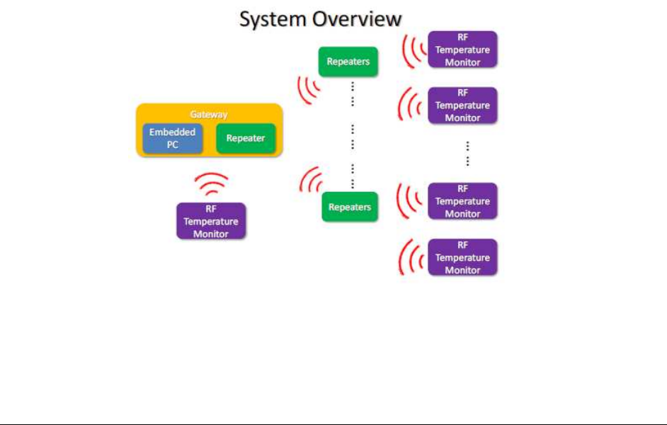
1. Overview of the TempTale RF
2 System
The TempTale
®
RF
2
system consists of infrastructure components and dataloggers. The infrastructure
components, TempTale RF
2
Gateways (Gateways) and TempTale RF
2
Repeaters (Repeaters), are installed
permanently while the TempTale RF
2
Dataloggers(Dataloggers) travel with the cargo and report their
data when they arrive at a location that has an installed TempTale RF
2
infrastructure.
This manual presents information relevant to Sensitech personnel who have been trained to install the
TempTale RF
2
system.
Each location can only have one Gateway installed but many Repeaters. The Gateway receives and
sends data to and from Repeaters using RF signals and also connects to the Internet to make this data
widely available. Repeaters receive and send data or commands to the TempTale RF
2
Dataloggers
through RF signals. The infrastructure devices, the TempTale RF
2
Gateway and TempTale RF
2
Repeaters,
communicate with each other at 2.4 GHz frequencies. However, the system can accommodate smaller
installations as the Repeaters and Gateways can also communicate directly with the TempTale RF
2
Dataloggers at 868 MHz or 915 MHz frequencies. This unique feature makes the infrastructure scalable
and flexible for use at large or small installations.
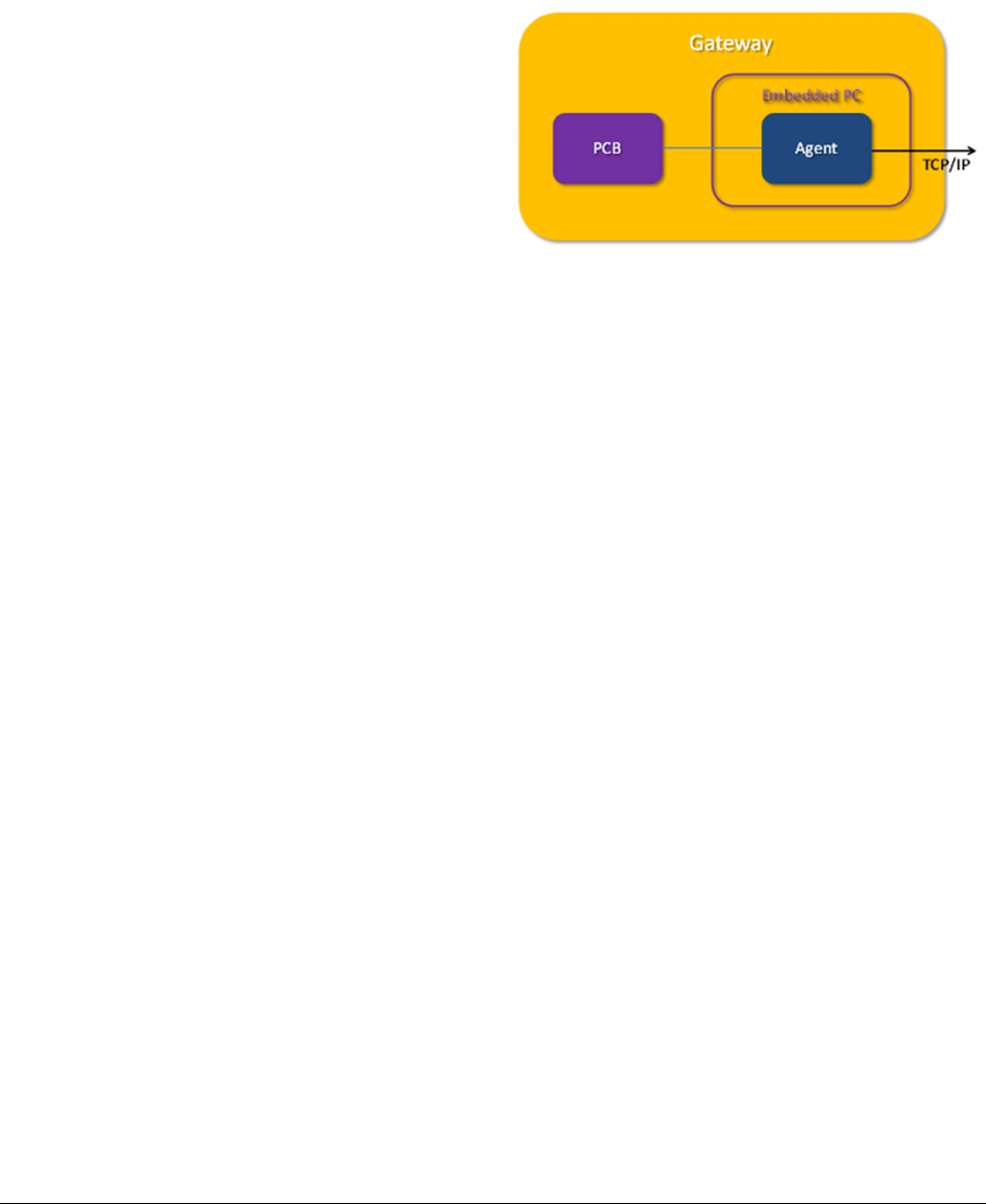
The Gateway consists of a ruggedized, embedded computer loaded with the programs required to read,
process the data and connect to the Internet. The Gateway programs also performs data buffering and
error checking and data decryption to insure data integrity.
Sensitech TempTale RF
2
System Installation Manual Revision 8
Page 2
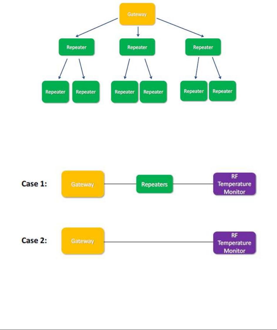
The layout of the system can be viewed as a tree with the Gateway as the root and Repeaters as nodes.
When planning for the layout of the TempTale RF
2
infrastructure, keep in mind that Repeaters can
communicate with other Repeaters, as shown below.
Since the Gateway is also capable of the same functions as Repeaters, a Gateway could also
communicate directly with Dataloggers to download data.
The maximum network coverage for a single Repeater or Gateway is about 80 - 100 meters, but this is
very dependent on the location. To cover more area, the network can be expanded simply by adding
more Repeaters.
Sensitech TempTale RF
2
System Installation Manual Revision 8
Page 3
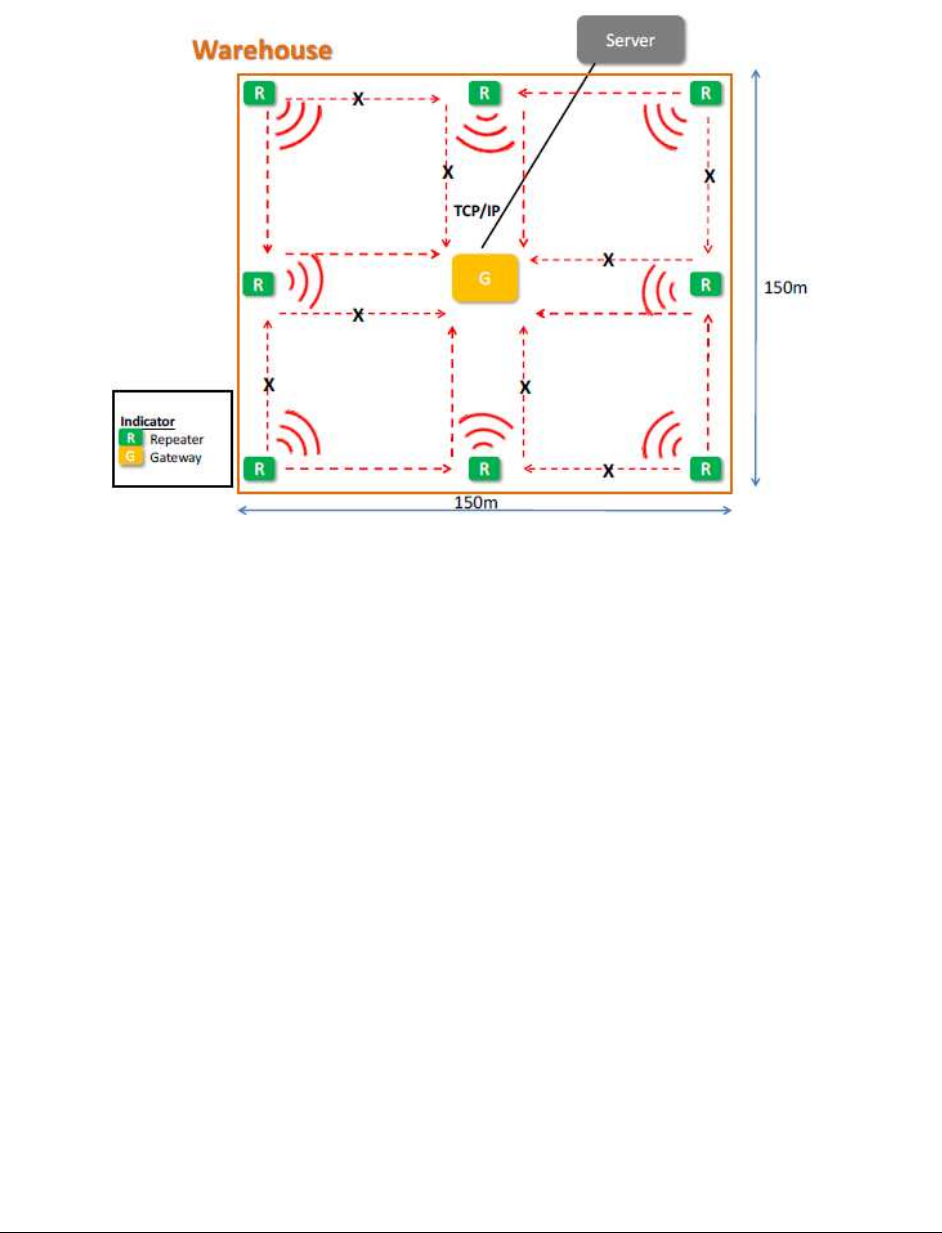
The following is a diagram illustrating the network layout for a 150 meter x 150 meter warehouse:
1.1. Important Installation Notes
Regarding RF2 installation, the following important rules must be taken into consideration when
determining where to mount the Gateway and Repeater infrastructure components:
1. The Gateway and Repeater MUST be mounted inside a building, where they would not be
exposed to rain or dripping water. They are designed to be installed in an location with
temperatures in the range of 0C to 40C, 10% to 90% humidity, non-condensing.
2. The Gateway and Repeater MUST NOT be mounted in a location where they would be exposed
to an explosive atmosphere, a corrosive atmosphere or conductive debris.
3. The Gateway and Repeater MUST ONLY be installed with the antennas included in the kit.
Changing antenna types or installation of an outside antenna is not permitted and will void the
Agency Approvals for the system.
4. The Gateway and Repeater MUST ONLY be powered by a +12 Vdc SELV Limited Power Source
only.
5. The RF
2
system has been tested for compliance to relevant standards and approved. Changes or
modifications not expressly approved by the party responsible for compliance could void the
user’s authority to operate the equipment.
CAUTION: RISK OF EXPLOSION IF BATTERY IS REPLACED BY AN INCORRECT TYPE. DISPOSE OF USED
BATTERIES ACCORDING TO THE INSTRUCTIONS.
Sensitech TempTale RF
2
System Installation Manual Revision 8
Page 4
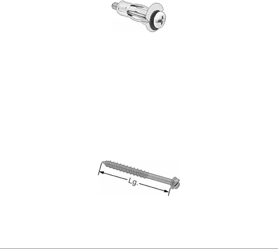
1.2. Mounting the Gateway and Repeater
The Gateway enclosure has a set of mounting tabs integrated into the enclosure, and the Repeater is
supplied with a plastic mounting plate. When securing either, the correct fasteners for the wall type
must be used.
For hollow wall construction studded with metal or wood framing and sheathed with Drywall,
Plaster or Plywood, an appropriate hollow wall such as a 3/16” toggle bolt or #10 re-usable
anchor.
Typical drill size is ½” for the 3/16” toggle bolt.
Each of the four Re-Usable Anchors used must be rated for 10 lb. (4.6 kg) minimum and be the
appropriate size for the sheathing thickness. Use #10 size minimum.
Typical drill size is 3/8” for the #10 re-usable anchor shown. Follow the manufacturer’s
instructions.
If the rear side of the sheathing is accessible, it is alternately acceptable to bolt the units to the
wall sheathing using four #10-#12 Pan Head Steel Machine Screws with fender washers and lock
nuts behind the sheathing. Length used must be adequate to fully engage all threads on the
nuts.
For concrete or masonry wall construction, use 3/16” concrete screws. Each of the four screws
must be rated for 10 lb (4.6 kg) minimum.
Typical drill size is 5/32” for the 3/16” concrete screw. Follow the manufacturer’s instructions.
Follow the manufacturer’s recommendation for drill depth for screws being used.

Sensitech TempTale RF
2
System Installation Manual Revision 8
Page 5
Various types of concrete inserts are available that are adequate for use in concrete, such as
conical lead or flanged Polypropylene that will be adequate for installation. They must be
individually rate to support 10 lb. (4.6 kg) minimum. Use sizes that support a #10 screw,
minimum.
Typical drill size is 5/16” for the #10 conical lead anchor for concrete. Follow the manufacturer’s
instructions. Follow the manufacturer’s recommendation for drill depth for insert being used.
Typical drill size is 1/4” for the #10 flanged Polypropylene anchor for concrete. Follow the
manufacturer’s recommendation for drill depth for insert being used.
Sensitech TempTale RF
2
System Installation Manual Revision 8
Page 6
2. TempTale RF
2 Gateway
As mentioned previously, the TempTale RF
2
Gateway is the core of the infrastructure for the network
and only one Gateway can be installed per facility. The Gateway is a ruggedized, self-contained
embedded computer with four antennas; two of the antennas are for 868 MHz or 915 MHz operation
while the other two antennas are for 2.4 GHz operation. The 2.4 GHz frequency is fixed regardless of
where the Gateway is installed, but the 868 MHz and 915 MHz frequencies are specific to the country of
installation. Some countries use 868 MHz, so when installing in those countries both 868 MHz antennas
must be used. When installing in countries where 915 MHz is the supported standard, two 915 MHz
antennas must be used. A universal power supply is shipped with the Gateway. When ordering the
Gateway, specify the location where it will be installed so Sensitech can provide the power cable with
the correct type of plug.
The TempTale RF
2
Gateway components are pictured in the next section.
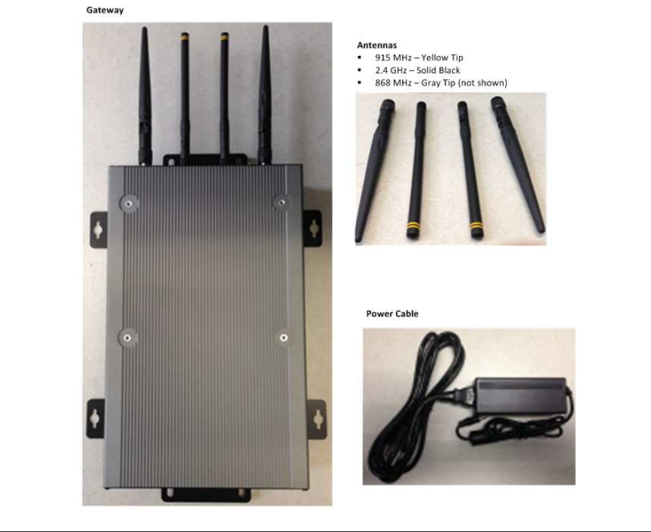
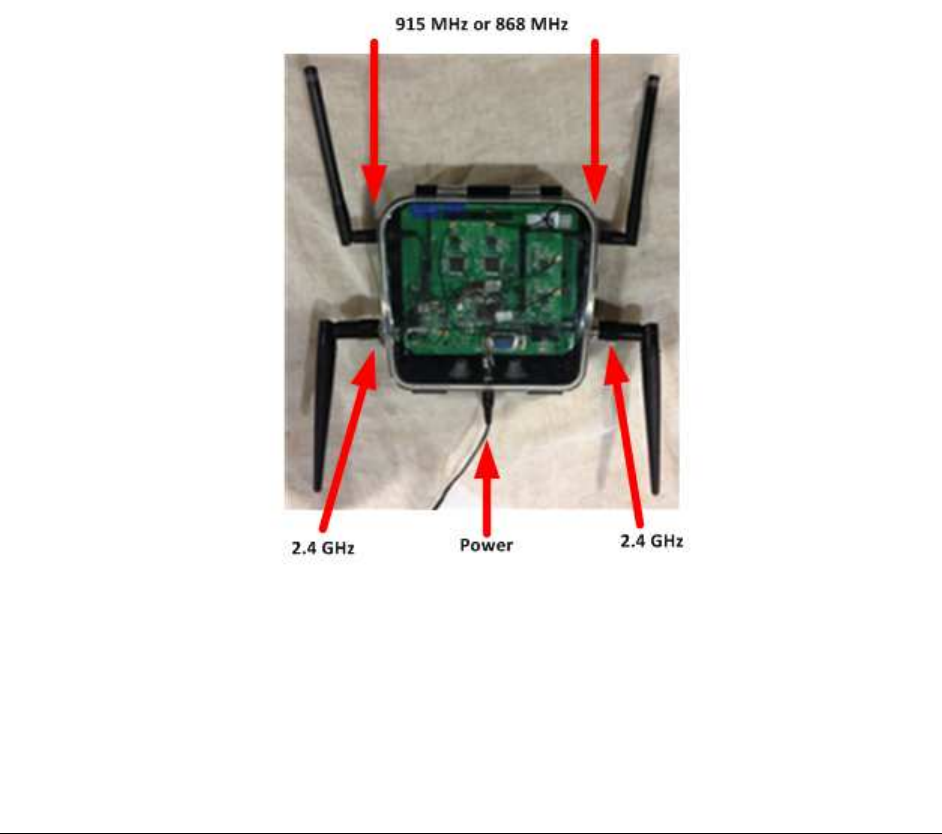
2.1. Gateway Components
Sensitech TempTale RF
2
System Installation Manual Revision 8
Page 7
2.2. Gateway Assembly
When you receive the Gateway, carefully remove it from the shipping container and inspect for damage,
especially if the shipping packaging appears to be damaged. If you determine there has been shipping
damage, contact the carrier immediately.
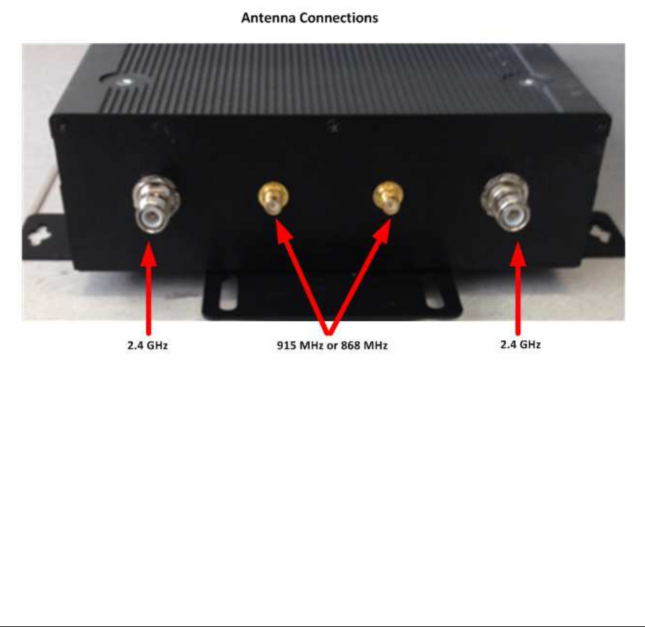
Determine if 915 MHz or 868 MHz antennas are required, and attach them as indicated in the diagram
below. The 915 MHz antennas have two yellow stripes and the 868 MHz antennas have two gray
stripes.
If you attach the wrong antennas, the RF performance of the Gateway may be degraded.
Sensitech TempTale RF
2
System Installation Manual Revision 8
Page 8
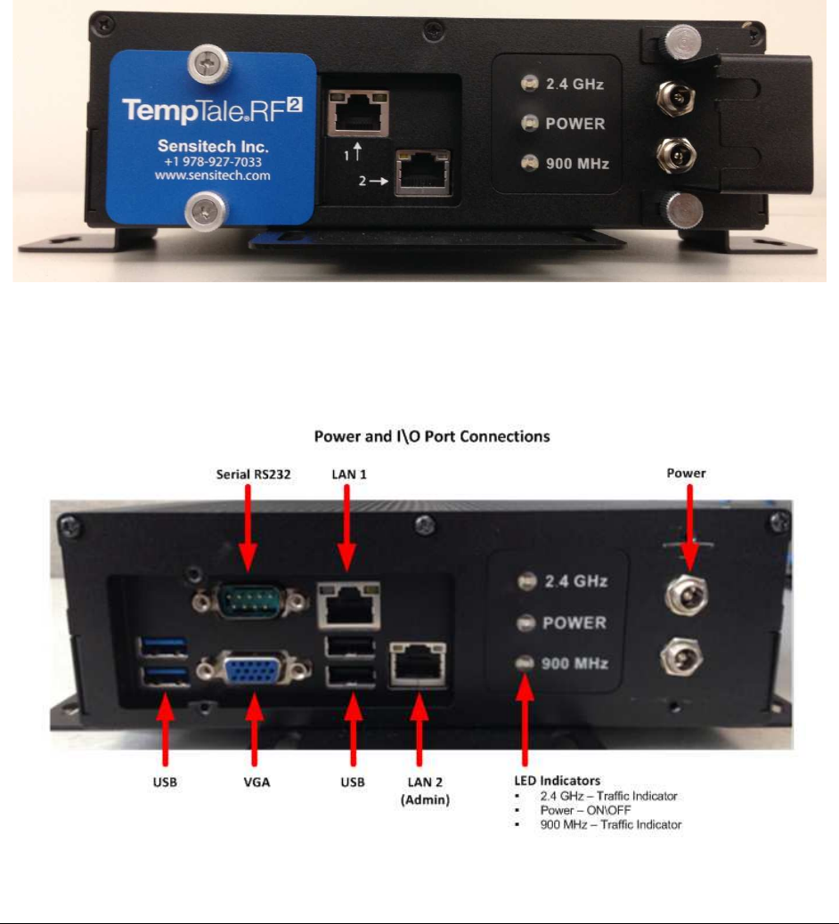
Next, connect the power supply provided at either of the two barrel power connectors provided. You
may need to first loosen the two thumbscrews that hold the securing plate into place. After you slide
the plate back, insert the power connector, slide the plate in place and tighten the thumbscrews.
NOTE: YOU SHOULD ONLY USE THE 12 VDC POWER SUPPLY PROVIDED! USING ANY OTHER POWER
SUPPLY MAY DAMAGE THE GATEWAY. THE SECURING PLATE IS NOT DESIGNED TO PHYSICALLY
SUPPORT THE POWER SUPPLY. DO NOT CONNECT THE REPEATER POWER SUPPLY TO THE GATEWAY!
There are additional connectors under the metal TempTale RF
2
nameplate, but they are typically not
required at installation. During installation, the plate should be left in place and only removed under the
direction of Sensitech factory personnel.

Sensitech TempTale RF
2
System Installation Manual Revision 8
Page 9
2.3. RF
2
Gateway Specifications
IMPORTANT: The RF2 Gateway contains a CR2032 lithium battery. This battery is not a customer
serviceable item and if replacement is needed, it should be done only by Sensitech personnel.
Input Power +12Vdc from a SELV limited power source
Weight 6 lbs.(2.75 kg)
RF Band: Gateway to Datalogger North American ISM Band from 902 – 928 MHz
European SRD Band from 863 to 870 MHz
Frequencies - 915 MHz band 921.5 MHz 923.0 MHz 923.5 MHz 924.0 MHz 924.5 MHz
Frequencies - 868 MHz band 866.1 MHz 866.5 MHz 866.7 MHz 867.1 MHz 867.3 MHz
RF Reading Distance 80 to 100 meters clear-line-of-sight
RF Data Rate 200 Kbit/s at 868 MHz; 250 Kbit/s at 915 MHz
RF Band: Gateway to Repeater 2.4 GHz ISM Band
RF Power Output - 2.4 GHz band 2442
MHz
2443
MHz
2444
MHz
2445
MHz
2446
MHz
2454
MHz
Sensitech TempTale RF
2
System Installation Manual Revision 8
Page 10
3. TempTale RF
2 Repeater
The TempTale RF
2
Repeater serves as a connection between the Datalogger and the Gateway. The
Repeater will receive the temperature records from the TempTale RF
2
Datalogger and then pass the
data to the Gateway which then delivers the data to the end-user software application or host
computer. An installation may require no Repeaters or many, depending on the coverage area needed.
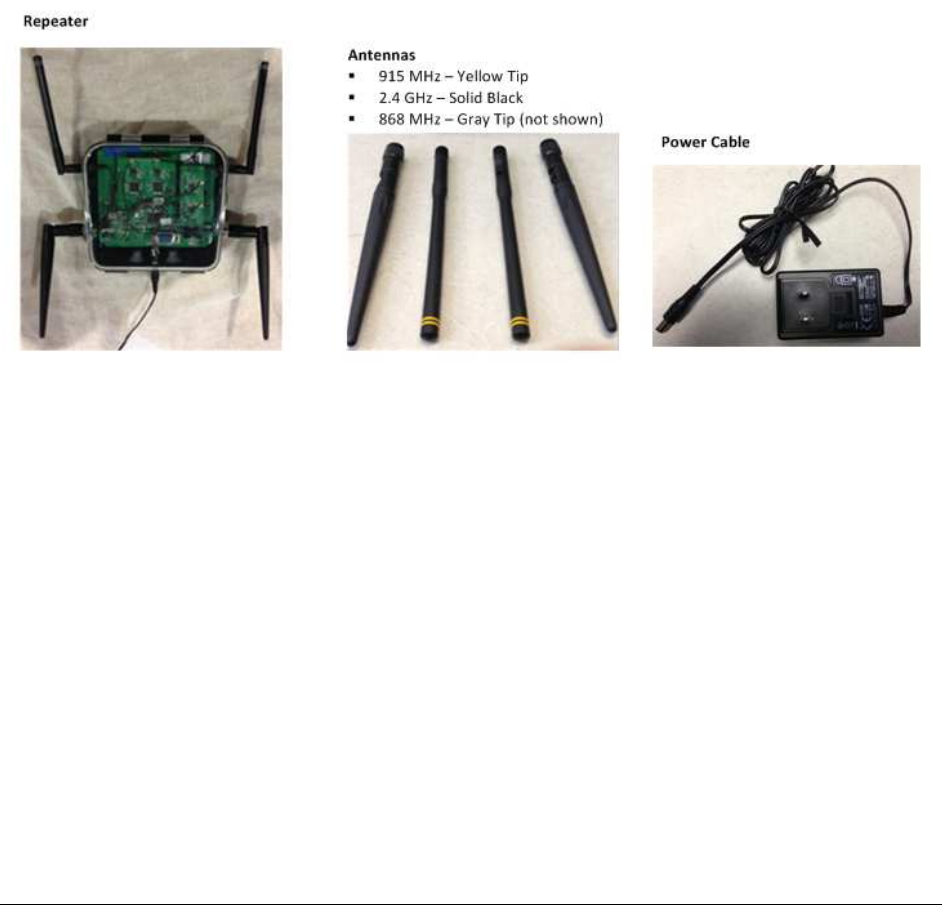
The Repeater components are pictured in the next section.
3.1. Repeater Components
Sensitech TempTale RF
2
System Installation Manual Revision 8
Page 11
3.2. Repeater Assembly
When you receive the Repeater, carefully remove it from the shipping container and inspect for
damage, especially if the shipping packaging appears to be damaged. If you determine there has been
shipping damage, contact the carrier immediately.
Determine if 915 MHz or 868 MHz antennas are required, and attach them as indicated in the diagram
below. The 915 MHz antennas have two yellow stripes and the 868 MHz antennas have two gray
stripes.
If you attach the wrong antennas, the RF performance of the RF
2
Repeater may be degraded!
Next, connect the power supply provided at the two barrel power connector provided facing down on
the Repeater enclosure.
NOTE: YOU SHOULD ONLY USE THE 12 VDC POWER SUPPLY PROVIDED! USING ANY OTHER POWER
SUPPLY MAY DAMAGE THE REPEATER. DO NOT CONNECT THE GATEWAY POWER SUPPLY TO THE
REPEATER!

Sensitech TempTale RF
2
System Installation Manual Revision 8
Page 12
4. Repeater Specifications
Input Power +12Vdc from a SELV limited power source
Weight 2 lbs.(1 kg)
RF Band: Repeater to Datalogger North American ISM Band from 902 – 928 MHz
European SRD Band from 863 to 870 MHz
Frequencies - 915 MHz band 921.5 MHz 923.0 MHz 923.5 MHz 924.0 MHz 924.5 MHz
Frequencies - 868 MHz band 866.1 MHz 866.5 MHz 866.7 MHz 867.1 MHz 867.3 MHz
RF Reading Distance 80 to 100 meters clear-line-of-sight
RF Data Rate 200 Kbit/s (868 MHz) , 250 Kbit/s (915 MHz)
RF Band: Gateway to Repeater 2.4 GHz ISM Band
RF Power Output - 2.4 GHz band 2442
MHz
2443
MHz
2444
MHz
2445
MHz
2446
MHz
2454
MHz
Sensitech TempTale RF
2
System Installation Manual Revision 8
Page 13
5. TempTale RF
2 Datalogger
The TempTale RF
2
Datalogger will travel with the cargo and continuously store temperature information
and a corresponding time stamp. The Datalogger will start operation when the “Start” button is
pressed.
The Datalogger also has two LEDs visible on the front panel; the greed LED blinks to indicate that the
Datalogger is operating, taking data points, while the red LED blinks to indicate an error or alarm
condition.
Until a Datalogger enters a TempTale RF
2
network, it will remain in low power mode where it does not
transmit but instead wakes up on a specific time interval to collect data. Each time the Datalogger
wakes up, it also checks if it can ‘hear’ the RF signals from a TempTale RF
2
infrastructure network. If it
does hear the RF signals, it communicates with the network. The Gateway can then determine what
information it needs from the Datalogger and send the appropriate commands.
Dataloggers also support a secondary download to a local PC using a Sensitech RF download cable. The
Datalogger can be downloaded using the Sensitech ColdStream or TempTale Monitor Download
application (TTMD).
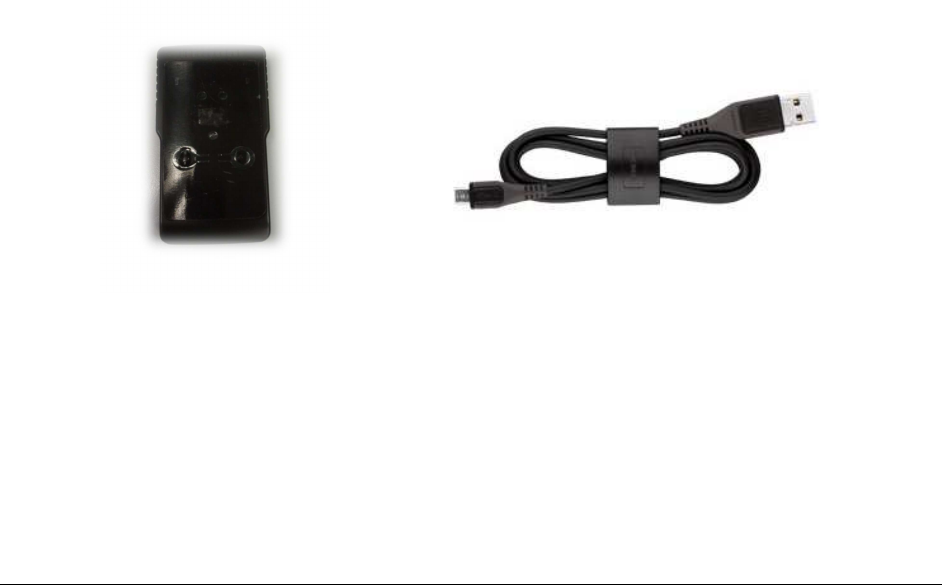
The Datalogger and secondary download cable are pictured in the next section.
5.1. Datalogger Components
5.2. RF Auto-Roaming
The TempTale RF
2
Gateway and Repeater infrastructure devices can be configured for operation at 868
MHz or 915 MHz, depending where they are installed. The Datalogger will automatically detect the
frequency of the infrastructure and switch to the corresponding frequency for the network detected.

Sensitech TempTale RF
2
System Installation Manual Revision 8
Page 14
5.3. Logging Data
The Datalogger has the capacity to store 1920 temperature records. When the 1920 record locations
are full, the Datalogger will stop taking new temperature records so no existing temperature records will
be overwritten. The time interval used to store data points is configurable based on the desired length
of operation and is programmed into the Datalogger when shipped.
When the Datalogger is running and no alarms have been triggered, the green LED will flash once every
four seconds. If the Datalogger is stopped and no alarms have been triggered, the green LED will flash
once every eight seconds. If there is no red Alarm LED and no green Status LED flashing, the device has
not been started and is not logging data points.
5.4. Alarms
Based on programmed parameters, the Datalogger makes its own decision as to whether it is in alarm
and if it is, it flashes a red LED to indicate that. Once the red LED is lighted because of an alarm, the
alarm will be sent to the TempTale RF
2
network infrastructure as soon as the Datalogger detects it.
If the red Alarm LED is flashing once every four seconds, this means an alarm was triggered and the
Datalogger is still running. If the LED flashes once every eight seconds, this means an alarm has been
triggered but the Datalogger has stopped taking data point.
There are four different alarm types and the logic behind each is listed below:
Alarm Type
Alarm Logic
Continuous events for high alarm Alarm will trigger when a certain number of consecutive
temperature records are higher than a predetermined level.
Cumulative events for high alarm Alarm will trigger when a certain number of cumulative
temperature records are higher than a predetermined level.
Continuous events for low alarm Alarm will trigger when a certain number of consecutive
temperature records are lower than a predetermined level.
Cumulative events for low alarm Alarm will trigger when a certain number of cumulative
temperature records are lower than a predetermined level.

Sensitech TempTale RF
2
System Installation Manual Revision 8
Page 15
5.5. Datalogger Specifications
IMPORTANT: The Datalogger contains a CR123A-type lithium battery and is not removable. If you plan
to dispose of the monitor, it must be done in a manner consistent with local and national regulations for
a device containing a lithium battery of this type.
RF Band: Gateway to Datalogger North American ISM Band from 902 – 928 MHz
European SRD Band from 863 to 870 MHz
Frequencies - 915 MHz band 921.5 MHz 923.0 MHz 923.5 MHz 924.0 MHz 924.5 MHz
Frequencies - 868 MHz band 866.1 MHz 866.5 MHz 866.7 MHz 867.1 MHz 867.3 MHz
RF Reading Distance 80 to 100 meters clear-line-of-sight
RF Data Rate 200 Kbit/s (868 MHz), 250 Kbit/s (915 MHz)
Anti-Collision Algorithm accommodates more than 200 active Dataloggers
Battery Life Shelf Operation
12 Months 12 Months
Battery Type Lithium CR123A
Temperature Range -30 C to +70 C
Temperature Accuracy -30 C to -10 C -10 C to +25 C +25 C to +70 C
+/- 1.0 C +/- 0.5 C +/- 1.0 C
Secondary Download Option Datalogger can be downloaded via USB using Sensitech ColdStream or
TempTale Manager Desktop applications
Sensitech TempTale RF
2
System Installation Manual Revision 8
Page 16
6. TempTale RF
2 Gateway Software
6.1. Software Overview
The program to perform the functionality of the RF
2
Gateway is installed on the embedded computer at
the factory.
This program handles 4 main functions:
• Manage the network and Dataloggers
• Download and transmit data to the server
• Manage alarms and event triggering
• Log network activity
6.2. Windows Services \ Applications
The functionality required for the Gateway has been divided into a number of different programs and
groups of programs, which are:
• Sensitech Network Manager
• Sensitech Rule Manager
• Data Transporter
• LCRF Configuration Utilities
• Sensitech Rule Viewer
• Sensitech Manual API Updater
Sensitech Network Manager
The Sensitech Network Manager is a service that manages the TempTale RF
2
Repeater network, handles
data routing and talks with Dataloggers.
Sensitech Rule Manager
Sensitech Rule Manager is the core of the system and it decides what commands are to be issued to
Dataloggers. It also handles all the rules updates and communicates with Sensitech’s web service.

Sensitech TempTale RF
2
System Installation Manual Revision 8
Page 17
DataTransporter
This is a utility provided by Sensitech to transfer downloaded Datalogger data to Sensitech’s server.
Configuration Utilities
This is the collection of software tools that communicate with the Sensitech Network Manger to allow
an operate to manually issue commands to the Gateway and Repeater network. These tools are usually
used exclusively for diagnostic and testing purpose.
Sensitech Rule Viewer
This is a tool that visually illustrates the rule system. It tracks all the Dataloggers in use in the system
and shows the progress on how the rules are being executed.
Sensitech Manual API Updater
This is a tool for network setup, used before deploying the system for unattended operation.

Sensitech TempTale RF
2
System Installation Manual Revision 8
Page 18

Sensitech TempTale RF
2
System Installation Manual Revision 8
Page 19
FCC Statement
NOTE: This equipment has been tested and found to comply with the limits for a Class B digital device,
pursuant to part 15 of the FCC Rules. These limits are designed to provide reasonable protection against
harmful interference in a residential installation. This equipment generates, uses and can radiate radio
frequency energy and, if not installed and used in accordance with the instructions, may cause harmful
interference to radio communications. However, there is no guarantee that interference will not occur
in a particular installation. If this equipment does cause harmful interference to radio or television
reception, which can be determined by turning the equipment off and on, the user is encouraged to try
to correct the interference by one or more of the following measures:
- Reorient or relocate the receiving antenna.
- Increase the separation between the equipment and receiver.
- Connect the equipment into an outlet on a circuit different from that to which the receiver is
connected.
- Consult the dealer or an experienced radio/TV technician for help.
Industry Canada Statement
This device complies with Industry Canada licence-exempt RSS standard(s). Operation is subject to the
following two conditions: (1) this device may not cause interference, and (2) this device must accept any
interference, including interference that may cause undesired operation of the device.
Le présent appareil est conforme aux CNR d'Industrie Canada applicables aux appareils radio exempts de
licence. L'exploitation est autorisée aux deux conditions suivantes : (1) l'appareil ne doit pas produire de
brouillage, et (2) l'utilisateur de l'appareil doit accepter tout brouillage radioélectrique subi, même si le
brouillage est susceptible d'en compromettre le fonctionnement.
CAN ICES-3(B)/NMB-3(B)