Sensor Developments 90439 Wheel Torque Sensor Transmitter User Manual M y System Operation 120216
Sensor Developments Inc. Wheel Torque Sensor Transmitter M y System Operation 120216
User Manual

~!@# Phone: (248) 391-3000
INNOVATIONS IN FORCE MEASUREMENT FAX: (248) 391-0107
Mail: Shipping:
P.O.Box 290 sales@sendev.com 1050 W. Silver Bell Rd.
Lake Orion, MI 48361-0290 http://sendev.com Orion, MI 48359
Braking Torque Sensor
with Torque, RPM and Temperature Measurement
Model 90360, 90438, 90439
Operators Manual
Mounting Instructions
1. Attach the brake-side adapter plate to the sensor using eight (8) 3/8-16 x ¾”, Grade 8
socket head cap screws. (The brake-side adapter plate is the plate that mounts to the brake
rotor or brake drum.) Note: Tighten cap screws to 350 in.-lbs., and use a “star” or “cross”
pattern when tightening. Take care not to pinch the wire between the adapter plate and the
sensor.
2. Remove the wheel or rim from the automobile.
3. Mount the brake adapter and sensor on the wheel hub of the vehicle, and secure it in place
using the proper lug nuts (or wheel studs).
4. Tighten the lug nuts (or wheel studs) to the proper torque, as specified by the vehicle
manufacturer. Use a “star” or “cross” pattern when tightening.
5. Attach the rim adapter to the sensor using eight (8) 3/8-16 x ¾”, Grade 8 socket head cap
screws. Note: Tighten cap screws to 350 in.-lbs., and use a “star” or “cross” pattern when
tightening. Take care not to pinch the wire between the adapter plate and the sensor, and
run the connector out the center hole in the adapter plate.
6. Mount the wheel and tire to the rim adapter, and secure it in place using the proper lug nuts
(or wheel studs).
7. Tighten the lug nuts (or wheel studs) to the proper torque, as specified by the vehicle
manufacturer. Use a “star” or “cross” pattern when tightening.
8. Plug the connector into the socket in the bottom of the electronics housing. There are red
dots on the connector and socket which will aid in aligning them properly.
9. Mount the electronics housing to the rim adapter, and secure it using the large captured
screw in the center.
Transmitter Operation (Model 90439)
The Model 90360 braking torque sensor has, supplied with it, the model 90439 FM transmitter. This
is a signal conditioning circuit that uses FM telemetry to transmit the signal(s) to a nearby stationary
receiver. The signals that are sent are braking torque, RPM and 2 user-specified temperatures.
1. Braking torque is measured using conventional strain gages. The excitation for the strain
gage bridge is provided by the on board electronics. The strain gage signal is fed into the
on board electronics where it is amplified, filtered, and digitized. See specifications for
update rate and accuracy.
2. RPM is measured using two accelerometers. Excitation for each accelerometer is provided
by the on-board electronics. The output signal of each accelerometer is filtered and
digitized. The digital signal is multiplexed with the torque signal and sent through the same
radio channel. See specifications for update rate and accuracy.
3. Temperature is measured using Resistance Temperature Devices (RTDs). RTDs are
resistive elements that have a very repeatable and nearly linear change in resistance with
respect to temperature. They do not require any special wiring or connectors. They are
excited by the on board electronics and the resulting signal is amplified, filtered, and
digitized. There are two connections for temperature on this unit, allowing the user to
make two independent temperature measurements. Both temperature signals are
multiplexed with the torque signal and RPM. See specifications for update rate and
accuracy.
Powering Up the Sensor
Once the on-board electronics have been installed on the wheel sensor, operation begins by pressing
on the power switch. At this time, the circuit wakes up and the red power indicator light will begin
to flash. It will be on for ½ second, off for 2 seconds, then repeat. The torque signal will be
immediately available at the receiver output. The output signals for RPM and temperature are
delayed for a few seconds, while the system self-calibrates. Details are given below.
Torque Measurement
The analog torque signal output represents the current torque applied to the sensor. Proper scaling
can be acquired/verified by pressing and holding the shunt switch on the sensor assembly. With the
shunt switch pressed, the torque sensor will be shunted with a resistor that produces a simulated
torque signal at the receiver’s torque output. Note that the switch must be held in this position.
Calibration is done as follows. First, make sure no torque is applied to the sensor during this process.
Now press and hold the shunt switch and measure the value that represents the simulated torque
value given in the data sheet. Once the shunt information has been taken, release the shunt switch
and the torque signal will return to the zero value. Using the data acquired from the shunt calibration
to configure the DAQ system, the user can now input torques to the wheel and accurately measure
the torque at the analog output on the receiver.
RPM Measurement
To aid the user in setting up the Data Acquisition (DAQ) system, the RPM signal provided to the
user immediately after powering up the sensor package will go through a calibration cycle. Keeping
the sensor stationary is not a requirement for this calibration. Upon power up, the analog output will
be held at a value representing 0 RPM. The value will be nominally 0V. This condition will be held
for 5 seconds. After 5 seconds, the output will shift to 3.5V nominal. This signal will represent the
‘RPM Cal Signal’ that is printed on the calibration data sheet. This value will also be held for 5
seconds. At the end of this time, the output will represent the current RPM. Using the calibration
information, the user can now measure the RPM of the wheel sensor at the RPM analog output on the
receiver. The signal output provided to the user does not account for direction. It is always positive,
no matter which direction the wheel is spinning. Also note that, although accelerometers are used to
RPM measurement, the RPM signal is designed to be insensitive to extraneous accelerations
produced by such things as a bump in the road.
Measuring Temperature
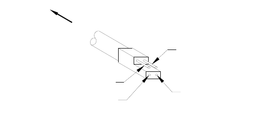
The only wiring at the wheel that needs to be done by the user is connecting the RTDs to the rotating
electronics package. Figure 1 shows the RTD wiring from the transmitter. The mating connector
may have different color wires, so always use Figure 1 as a guide. RTDs are not polarized devices, so
it doesn’t matter which lead connects to the positive terminal and which connects to the negative
terminal. The + and – are only shown to indicate which terminal is the excitation source and which
is ground. Also note that this system is designed to accept only 100 ohm, .385 ohms per degree C
RTDs. Other types will give inaccurate results. Mechanically fasten the RTDs to the part that is to
be measured and wire the leads as shown in Figure 1. Since the electronics package will be rotating
with the wheel, temperature can only be measured on parts that rotate along with the wheel. Use
care to route wires so they won’t get caught on stationary objects, such as the brake caliper.
The temperature signals are provided to the user at the Temp 1 and Temp 2 outputs on the receiver.
The measurement range is –100 deg C to +500 deg C. The output voltage is nominally 10mV per
deg C with 0 deg C producing 0V. This means that –100 deg C will be nominally –1V and +500 deg
C will be nominally +5V. Earlier, it was stated that RTD’s are nearly, but not quite, linear.
Correction for this nonlinearity is done in software so the analog output appears linear to the user.
See the calibration data sheet for unit specific calibration information.
To aid the user in setting up the DAQ system, there are 2 internal references that are switched in
upon powering up the rotating assembly. Immediately after power up, a 0 deg C reference is
switched in and held for 5 seconds. After the 5 seconds expire, a 380 deg C reference will be
switched in and held for 5 seconds. When this time expires, the outputs will begin providing the user
with the temperature at the corresponding RTD.
If only one channel of temperature measurement is desired, or no temperature measurement is
desired, simply leave the unused RTD input unconnected. To indicate a “no RTD connected” status,
the transmitter sends a code that causes the corresponding temperature output on the receiver to
move to a nominal –5V.
To Transmitter
BLK (-RTD2)
RED (+RTD2)
GRN (+RTD1)
WHT (-RTD1)
Figure 1. RTD Wiring
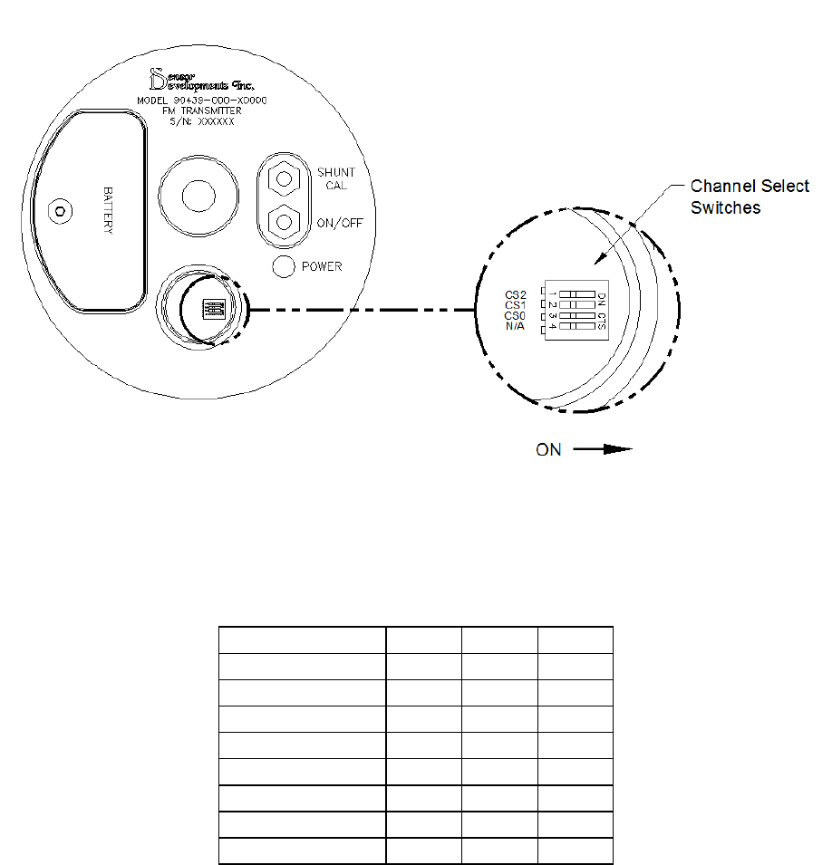
Channel Selection
The on board electronics package contains an FM transmitter to transmit the data. The transmitter
operates on one of eight channels. The channel is user-selectable via a small set of switches. To
change the channel selection, open the channel select cover using a dime. A flashlight may be
required to see the switches. They are mounted to the PCB and the switch selections can be changed
using a long, narrow screwdriver or similar device. See Figure 2 and Table 1 for info on how to
select the desired channel or transmitting frequency. IMPORTANT! ALWAYS DISCONNECT
THE BATTERY WHEN CHANGING THE TRANSMITTING FREQUENCY. ALSO, DO
NOT CONNECT ANYTHING TO THE HEADERS ON THE PCB OR CALIBRATION AND
TEMPERATURE COMPENSATION WILL BE COMPROMISED.
Figure 2. Channel Select Switches
Freq. (MHz) CS2 CS1 CS0
903.3 On On On
906.3 On On Off
907.8 On Off On
909.3 On Off Off
912.3 Off On On
915.3 Off On Off
919.8 Off Off On
921.3 Off Off Off
Table 1. Transmitter Channel Selections
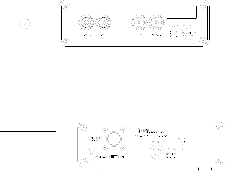
Receiver Operation (Model 90438)
The included model 90438 FM Receiver consists of a 900MHz radio receiver, control electronics,
digital to analog (D/A) converter(s) and buffer/filter(s). Operation of the receiver is as follows:
1. Connect the DAQ system to the signal outputs as shown in Figure 3.
2. Screw the antenna onto the antenna connector on the rear panel as shown in Figure 4.
3. Select the desired channel by the proper switch combination as shown in Table 2. Use
Figure 4 as a reference for the switch location. Make sure to set the receiver to the
same channel as the transmitter.
4. Connect power to the power input pins as shown in Figure 4. Turn on the power switch
and the “power” indicator will light. Maximum input voltage is 16 volts DC.
5. Turn on the transmitter and make sure it is near the receiver. In some applications, it
will not be possible to get the transmitter and receiver close enough to each other for
reliable operation. In this case, unscrew the antenna from the receiver and install the
antenna extension cable (supplied) between the antenna and the receiver. It will now be
possible to place the receiving antenna closer to the transmitter.
The unit will receive a digital signal from the transmitter on the channel selected in step 3 above.
When this happens, the yellow “carrier detected” indicator will light. The green “good data”
indicator will light showing that the digital data were recovered without error. The transmitted data
are then fed to the Digital to Analog converter, and on to the corresponding analog output. In the
event that the data are found to be in error, the good data light will go out, a beeper will sound a
short tone and the good data relay contacts will close. In the event that the unit loses power, the
relay contacts will rest in the closed position, indicating an error. The contacts are available at the
power connector as shown in Figure 4. When wired to the DAQ system, the relay contacts will
indicate a failure in the data transmission. Recording the state of the contacts along with the rest of
the data can be helpful during data analysis.
The receiver has four analog outputs provided with BNC-style connectors. See Figure 3. There is
one output for wheel torque, one output for RPM and two outputs for temperature. Each analog
output is buffered and filtered. The filter is there to smooth the steps that are inherent in the output
of the D/A converter.
This unit comes with adjustments for zero and span on the torque (sensor) output, along with a span
adjustment for the built in display (meter). See Figure 3. Note that, in pre-installed and pre-
calibrated systems, the span adjustments have been set at the factory, and covered with a calibration
sticker. In this case, do not adjust the sensor span or meter span, else the calibration information
furnished with the system will be void, and a factory recalibration will be required. The built-in
display, or meter, is simply a voltmeter connected to the sensor output signal. If adjustments to the
sensor span and the meter span are required, always adjust the sensor span first. For the sensor
output, the zero adjustment range is +/-20% of the full-scale output range and the span adjustment
range is +/-10% of the full-scale output range. The meter has a span adjustment range that covers 0
to 2000 counts with a decimal point that is factory set. With 5 volts at the sensor output, units that
have the meter configured for voltage will be adjusted to show 5.00 counts. Units that have the
meter configured for engineering units will show those units in a unit that best fits the display. For
example, if the sensor capacity was 7000 pounds, the meter would display 7.00 and the units would
be understood to be in 1000’s of pounds.
When measuring the signal outputs, note that the signal ground is isolated from the power supply
ground to prevent ground loops. Measurements must be taken with respect to the signal ground and
not the power ground. The signal ground is common for all output signals. The signal ground may
be connected to the power supply ground without damaging the unit. Some applications may require
that they be connected. For example, when using a DAQ system with differential inputs to read
these signals, it is important to ground the negative signal input on the DAQ system to provide an
absolute point of reference for the input. Without such a connection, erroneous data may be
collected. For DAQ systems with grounded single-ended inputs, this is not an issue.
SIGNALCOM
Figure 3. Receiver Connections, side 1
POWER IN & DIGITAL OUT
A +12V
B Gnd
C Good Data Relay-N/O
D Good Data Relay-Common
E Do Not Connect
F Do Not Connect
Figure 4. Receiver Connections, side 2

Freq. (MHz) CS2 CS1 CS0
903.3 On On On
906.3 On On Off
907.8 On Off On
909.3 On Off Off
912.3 Off On On
915.3 Off On Off
919.8 Off Off On
921.3 Off Off Off
Table 2 – Receiver Channel Selections
Receivers with the rechargeable battery option installed can be operated for up to 3 hours with the
internal Ni-Cd battery. The battery must be fully charged before operation. To charge the battery,
simply power the receiver with the supplied AC/DC adapter. Charging will take place both when the
receiver is in operation and when it is turned off, so long as it’s connected to the AC/DC converter.
A full charge typically will take place overnight (14 - 16 hours).
FCC NOTICE
This device complies with Part 15 of the FCC rules. Operation is subject to the following two
conditions: 1. This device may not cause harmful interference.
2. This device must accept any interference received, including interference that may
cause undesired operation.
This equipment has been tested and found to comply with the limits for a class B digital device,
pursuant to part 15 of the FCC Rules. These limits are designed to provide reasonable protection
against harmful interference in a residential installation. This equipment generates, uses and can
radiate radio frequency energy and if not installed and used in accordance with the instructions, may
cause harmful interference to radio communications. However, there is no guarantee that
interference will not occur in a particular installation. If this equipment does cause harmful
interference to radio or television reception, which can be determined by turning the equipment off
and on, the user is encouraged to try to correct the interference by one or more of the following
measures:
1. Reorient or relocate the receiving antenna.
2. Increase the separation between the computer and receiver.
3. Connect the computer into an outlet on a circuit different from that to which the
receiver is connected.
4. Consult the dealer or an experienced radio/TV technician for help.
CAUTION
In order to maintain compliance with FCC regulations, shielded cables must be used with this
equipment. Operation with non-approved equipment or unshielded cables is likely to result in
interference to radio and TV reception. The user is cautioned that changes and modifications made
to the equipment without the approval of the manufacturer could void the user’s authority to operate
this equipment.

SPECIFICATIONS
Transmitter Power Supply
Input Voltage .............................................................................................................................. 7-15VDC
Current Consumption .......................................................................................................................45mA
Recommended Battery ............................................................................................... 9VDC Alkaline***
Approximate Battery Life .............................................................................................................. 8 Hours
Receiver Power Supply
Input Voltage ..................................................................................................................... 11 – 16VDC **
Current Consumption ............................................................................................................ 750 mA max.
Sensor Output
Sensor Resolution .............................................................................................. 12 bits (11 bits plus sign)
Sensor Accuracy ................................................................................................... +/-.05% of Full Scale *
Output Voltage Range ................................................................................................................ +/-5VDC
Optional Output Voltage Range ............................................................................................... +/-10VDC
Update Rate ................................................................................................................ 940 updates/second
Front End Low Pass Filter ............................................................................ 4 pole butterworth @ 300Hz
RPM Output
RPM Resolution (1200) ................................................................................................................ 10 RPM
RPM Resolution (1750) ................................................................................................................ 14 RPM
RPM Accuracy ........................................................................................................... +/-2% of Full Scale
RPM Full Scale ......................................................................................................................... 1200 RPM
Optional RPM Full Scale .......................................................................................................... 1750 RPM
Output Voltage Range .............................................................................................................. 0 to 5VDC
Optional Output Voltage Range ............................................................................................. 0 to 10VDC
Update Rate .................................................................................................................. 60 updates/second
Low Pass Filter ............................................................................................... 2 pole butterworth @ 48Hz
Temperature Outputs
Temperature Resolution .............................................................................................................. .5 deg C
Temperature Accuracy ............................................................................................................. +/-2 deg C
Temperature Range of Measurement ........................................................................ –100 to +500 deg C
Output Voltage Range .......................................................................................................... -1 to +5VDC
Optional Voltage Range ..................................................................................................... –2 to +10VDC
Update Rate .................................................................................................................... 2 updates/second
Temperature
Operation ................................................................................................................................ 0 – 70 deg C
Drift ................................................................................................................................. .005% per deg C
* Electronics only. Sensor design can affect specifications. See data sheet provided.
** 14VDC – 16VDC to recharge battery.
*** For temperatures below 5 deg C, a lithium battery is recommended.
SERVICE WARRANTY
Sensor Developments Inc. warrants its products to be free from defects in material and workmanship
for a period of one year from shipment from our factory. In that period we will, at our option, repair
or replace a defective component or entire product which has been submitted for our examination.
This is our sole obligation. We are not responsible for any costs or liabilities arising from but not
limited to de-installing, consequent or collateral damage, delays, loss of use, re-installing, or any
others. The warranty is in effect provided the component or product is properly used in the
application for which it is intended. Products which have been modified without Sensor
Developments Inc.’ approval, on which repairs have been attempted by non-qualified persons, which
have been subjected to physical or electrical stress beyond our ratings, or which have had their
identifying marks removed or altered are not covered by this warranty.
In cases of incorporation of a product by the user in a larger system provided by a third party or sold
on to a third party, we make no warranties except those above. We assume no responsibility for
fitness for purpose in these circumstances.
Warranty returns must be authorized by us and shipped prepaid to us. Our return authorization
number must appear on the packaging and any correspondence. We will return the goods prepaid.
Products, which have been exposed to hazardous materials, will not be accepted unless they have
been properly decontaminated. Sensor Developments Inc. Inc. reserves the right to refuse any
shipment which it believes may create a physical or health hazard to our employees.
Products returned out of warranty for repair are subject to a minimum inspection fee. The fee is
waived if the repair is authorized. It is also waived if the product is un-repairable and/or a
replacement is purchased.
REPAIR SERVICES
Sensor Developments Inc. products requiring repair should be returned freight prepaid to: Attention -
Service Department. Information should be included stating what is wrong with the item(s) returned
and name of contact. No item shall be returned for repair which has been exposed to hazardous
materials without suitable decontamination. Hazardous materials include, but are not limited to:
poisons, materials capable of producing toxic fumes, radioactive waste materials which can spread
viral or other diseases and materials which pose hazards by airborne ingestion, such as asbestos.
Sensor Developments Inc. reserves the right to refuse and/or return any shipment which it believes
poses any health risk to its employees. Unless the repair is covered under the terms of Sensor
Developments Inc.’ warranty, there will be a minimum inspection and evaluation fee for each item
returned. This fee may be waived if the item proves non-repairable, and a comparable replacement is
ordered.
Revised: February 6, 2017