Sensormate Enterprise RS96390-01 Remote Control Damping System User Manual INSTALLATION INSTRUCTION
Sensormate Enterprise Co., Ltd. Remote Control Damping System INSTALLATION INSTRUCTION
manual
INSTALLATION INSTRUCTION 96399
Rev A
WIRELESS REMOTE CONTROL DAMPING SYSTEM
READ INSTRUCTION THOROUGHLY FROM START TO FINISH BEFORE BEGINNING INSTALLATION
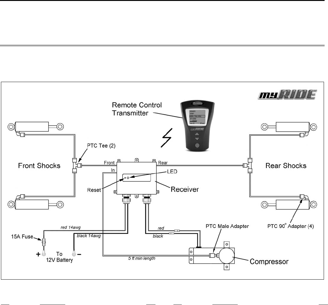
RS999705 Assembly Diagram
Parts List
P/N Description Qty.
96111 Tire Wrap Kit 1
Black Tie Wrap 30
96364 Shock Adapter Kit 1
96303 Push-to-connect 90° Adapter 4
O-ring 4
Gasket 4
96381 Hardware Kit 1
96301 Push-To-Connect Tee 2
96385 Female Bullet Connector 1
96386 Push-To-Connect male Adapter 1
15 Amp Fuse 1
Allen Wrench 1
10-24 x 1.25 HHSTS 8
P/N Description Qty.
96382 Compressor Kit 1
96351 Compressor Assembly 1
DNX18003 Tubing Cutter 1
96383 Air Line Tubing, 70 ft. 1
96390 Receiver/Transmitter Kit 1
96387 Receiver 1
96388 Remote Control Transmitter 1
96389 AAA Batteries, 3 Pack 1
96399 Instructions 1
96399-1 Quick Reference Guide 1
IMPORTANT NOTES!
A. Refer to your owner’s manual for proper vehicle lifting
techniques. Never work under a vehicle that is not supported by
jack stands.
B. Always disconnect battery before working on the electrical
system.
C. The receiver and air compressor can be mounted in other
locations besides the engine compartment. Choose a high and dry
location that best fits your application. If extra wire is needed,
splice 14awg only. The compressor can also be mounted in any
position but should be located near the receiver.
D. Route all wires and air lines away from hot or sharp objects.
Do not allow air line to kink, bind or make contact with moving
components. Turn the wheels completely left and right to verify
clearance. Inspect the air lines before and after lowering the
vehicle to the ground.
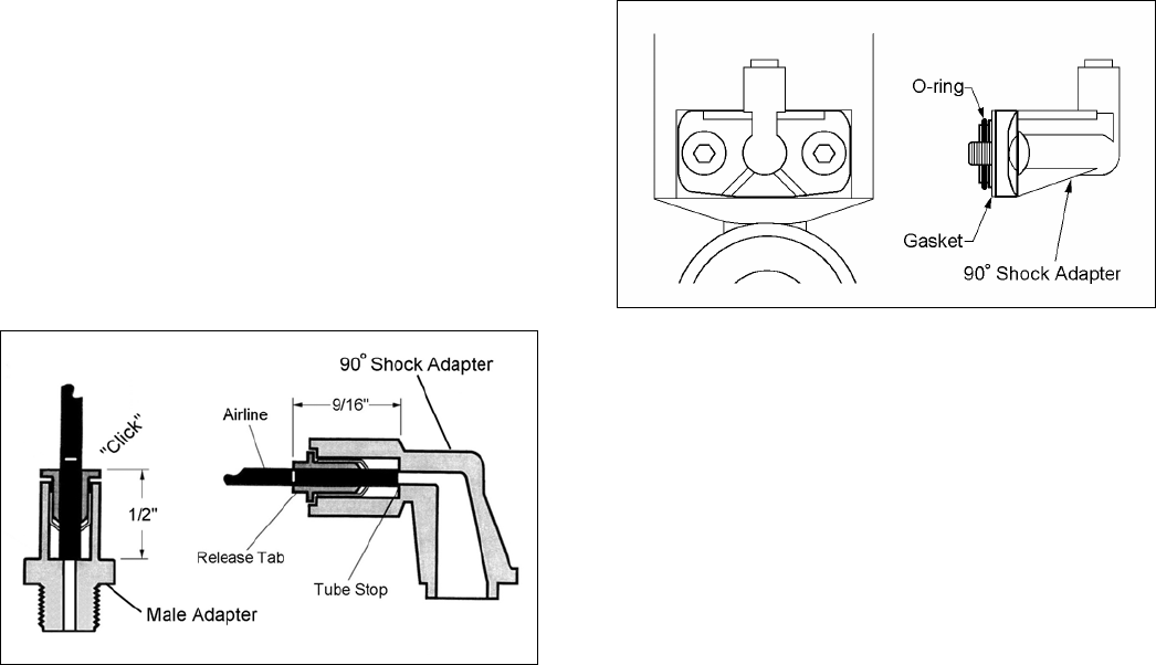
E. Dipping the end of the air line tubing in clean motor oil before
insertion will improve the seal. The air line tubing must be
inserted 9/16” for the shock adapter and 1/2” for the tee and
male adapter. Cut tubing on white marks (9/16” apart) to help
with the insertion depth. Push-to-connect fittings will “click” when
the tubing is fully inserted. See Illustration 1.
Illus. 1
F. To remove the air line tubing, deflate system, push down on
quick release tab and pull line. Trim air line 9/16” with supplied
tube cutter before reinstalling. Do not remove airline while system
is pressurized.
INSTALLATION:
1. Thread PTC male adapter into compressor outlet. Do not
over tighten. Install female bullet connector on compressor black
wire.
2. Pick a location inside the engine compartment to mount the
receiver and compressor, usually on the same side as the vehicle
battery. Refer to “Important Notes”.
3. Using the receiver and compressor as templates, mark and
center punch the mounting hole locations. Drill the appropriate
hole at each location.
4. Attach the receiver and compressor with the supplied
hardware. Use rubber isolators on the compressor to reduce
vibration.
5. Connect the electrical wires from the compressor to the
matching wires on the receiver. Refer to assembly diagram. Do
not connect battery wires at this time.
6. Turn the adjuster knob on each RS9000X shock to position 1
then remove the adjuster assemblies. Save screws for reuse.
Remove any gasket material left on shocks.
7. Install gasket and slide o-ring on 90° shock adapter. See
illustration 2. Coat the o-ring with oil or lithium grease.
Illus. 2
8. Using the supplied allen wrench, carefully attach the adapter
assembly to the shock with the original screws. Tighten screws
evenly. Do not over tighten.
9. Repeat steps 6 through 8 to install the rest of the 90°
adapters.
10. Using the supplied tube cutter, cut two pieces of air line
tubing and connect the front shocks together with a push-to-
connect (PTC) tee. Refer to assembly diagram and Important
Notes.
NOTE: Before cutting the air line tubing, add an additional 8
inches to allow for suspension movement. Cuts must be clean and
square, please use the supplied tube cutter only.
11. Repeat step 10 to connect the rear shocks together.
12. Measure and cut air line tubing to connect the front and rear
shocks to the receiver. Refer to assembly diagram. Secure tubing
with tie wraps.
13. Cut 5 feet of air line tubing. Coil the air line (if necessary)
and connect the compressor to the receiver inlet.
14. Attach the red wire from the receiver to the positive battery
post. Attach the black wire to the negative battery post.
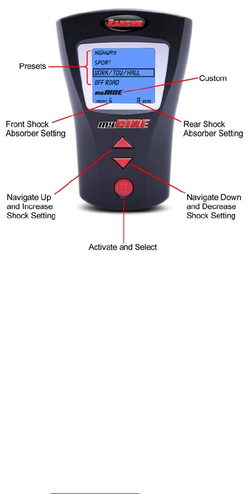
15. Install batteries in the remote transmitter. The transmitter
automatically performs a self-diagnosis and scrolls through the
settings. Once completed, the MYRIDE setting is selected and
shock damping is set to a minimum.
NOTE: Allow the display to stop flashing before making another
selection. If too many selections are made, an error may occur
(“E” on the display). Push set button to restart.
OPERATION:
This device complies with Part 15 of the FCC Rules. Operation is
subject to the following two conditions:
(1) This device may not cause harmful interference
(2) This device must accept any interference received,
including interference that may cause undesired operation.
Changes or modifications not expressly approved by the party
responsible for compliance could void the user's authority to operate
the equipment.
If display is blank, push set button to activate.
To adjust shock absorbers to a preset setting:
• Push the up or down arrow until the desired preset is
selected.
• Push set button once to accept. The selection flashes and
the compressor starts and stops automatically.
To adjust shock absorbers to a custom setting:
• Push the down arrow until MYRIDE is selected.
• Push set button once to select the front shocks.
• Push up arrow to increase stiffness or down arrow to
decrease stiffness.
• Once the desired ride control is reached, push set button
to accept. Rear shocks are automatically selected.
• Push up arrow to increase stiffness and down arrow to
decrease stiffness.
• Once the desired ride control is reached, push set button
to accept. The selection flashes and the compressor
starts and stops automatically.
Rancho Industries U.S.A. Limited Warranty
RS9000 RCX Remote Control
The RS9000 RCX Remote Control (RS99701) is limited to a 2-year, 24,000 mile warranty. Tenneco Automotive warrants each new RS9000
RCX Remote Control system against factory defects in material and workmanship (except for finish, including the shock boot) for the first to
occur of 2 years or 24,000 miles after the date of purchase.
For more warranty information or technical assistance, visit our website at www.gorancho.com or call 1-734-384-
7804.
TROUBLESHOOTING GUIDE
Tool List
• Spray bottle containing a 20% soapy water solution • Flashlight
• Plumber grade Teflon tape or thread sealant • Air line cutter (supplied with kit)
• Allen wrench (supplied with kit) • 12vdc circuit tester
• Small container with 1 ounce of clean motor oil
Transmitter, Receiver & Compressor
Check batteries in remote control transmitter. Check inline fuse. Check wire connections at 12V battery.
Check wire connections between receiver and compressor. To reset the receiver, push reset button until
solid green light appears. To reconnect receiver to transmitter, push reset button until flashing green light
appears.
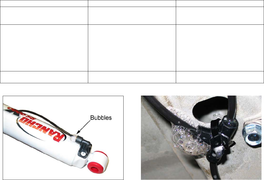
Leak Detection
Pressurize system to nine. Spray air line connections and adapters with soapy water until the leak is found
(escaping bubbles). See illustrations below. DO NOT SPRAY ELECTRICAL COMPONENTS. When leak
is detected, release pressure and follow system chart.
System Chart
Leak Location Possible Source Corrective Action
Compressor outlet • Loose fitting
• Thread seal
• Tighten fitting. Do not over tighten
• Remove fitting, clean and install Teflon
tape or thread sealant
Air line connection at push-to-connect
adapters and fittings. See illustrations below.
• Damaged air line end
• Air line not fully inserted/seated
• O-ring seal inside push-to-connect fitting
• Re-cut end of air line with supplied air
line cutter. Line must be re-cut every
time it is removed.
• Push air line into shock adapter 9/16”
Push air line into male adapter and tee
fitting 1/2”. See Important Notes.
• Install two drops of oil into fitting or dip
end of air line in oil
Mounting surface of 90° shock adapter • Misaligned or damaged o-ring. Refer to
illustration 2
• Reinstall or replace o-ring. Coat o-ring
with oil or grease