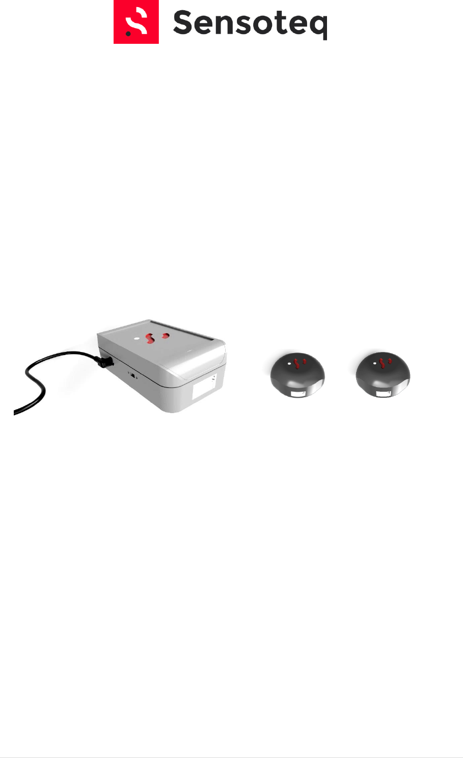
Sensoteq ANTS1001 Smart Wireless Vibration Sensor User Manual
Sensoteq Ltd Smart Wireless Vibration Sensor
Sensoteq >
User Manual
1 | P a g e
Sensoteq® Wireless Vibration Sensor
Installation and Operation Manual

2 | P a g e
Contents
1. Introduction .................................................................................................................................... 4
2. Gateway Installation ....................................................................................................................... 5
3. Sensor Installation........................................................................................................................... 8
4. Sensor Modes ................................................................................................................................. 9
5. HMI .................................................................................................................................................. 9
6. Handling ........................................................................................................................................ 11

3 | P a g e
FCC Notice
FCC ID: 2ANL3-ANTS1001
This device complies with Part 15 of the FCC Rules. Operation is subject to
the following two conditions:
(1) This device may not cause harmful interference, and
(2) This device must accept any interference received, including interference
that may cause undesired operation.
This equipment complies with FCC radiation exposure limits set forth for an
uncontrolled environment. End users must follow the specific operating
instructions for satisfying RF exposure compliance. This transmitter must not
be co-located or operating in conjunction with any other antenna or
transmitter.
Changes or modifications not expressly approved by the party responsible for
compliance could void the user's authority to operate the equipment
4 | P a g e
1. Introduction
Sensoteq Ltd design and manufacture bespoke low power wireless sensors for remote Machine Health
Monitoring. Providing Continuous measurement of Critical Parameters such as Temperature and
Vibration in a variety of industrial applications where the environment can be extremely harsh and
constantly changing. Fully internet connected, it gathers data from systems positioned all over the
world. Users can then be alerted of faults ahead of time to help with predictive maintenance and
reduce downtime.
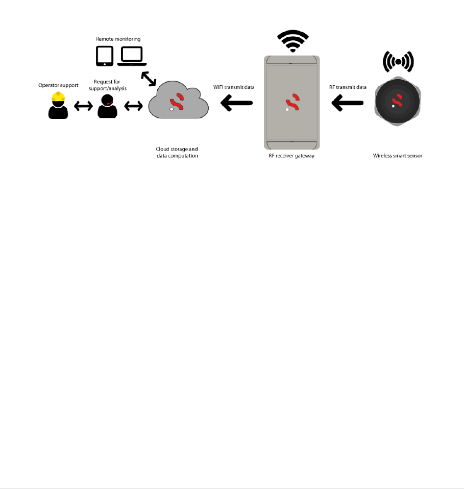
The system consists of a number of wireless sensors (depending on the application) mounted around
a machine, monitoring key parameters such as vibration and temperature, then transmitting the data
securely to a cloud via a local gateway. This information/data displayed on a mobile device via a
webpage or an app can then be used to predict maintenance, reduce downtime and help run the
machine more efficiently.
Typical System Architecture
This document will indicate how to install and visualise this system into the target application.
5 | P a g e
2. Gateway Installation
Authorisation from responsible site safety officer must be taken prior to any installation, and
Health and Safety precautions must be taken during installation. We recommend that installation is
performed by qualified Sensoteq personnel or Sensoteq trained personnel.
An appropriate location should be determined within 100m range of the sensor to ensure sufficient
RF reception, WIFI reception and a 12V regulated power supply.
To configure the receiver a smartphone, tablet or laptop is required which is capable of connecting
to a WiFi network.
Please note this guide assumes the receiver has been prepared for setup, e.g. antennas attached and
taken to the final install location (as it must be able to connect to the WiFi network at this point).
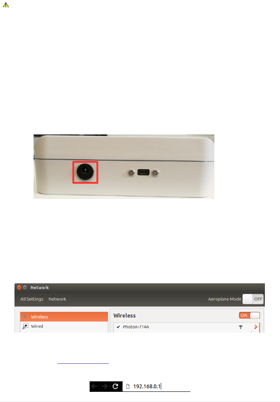
First please connect the mains DC jack plug to the receiver, using the port denoted in the picture
below.
The micro USB connector should not be used as this is only for serial data connections.
Once the receiver has been powered up open your WiFi network connections (this will differ per
operating system) and look for a network named Photon-XXXX where the XXXX is four random
characters, e.g. Photon-CE3C. This will be an open network (no password) required, simply connect
to it. If the network does not appear then try re-scanning for new WiFi networks. The below example
shows connecting to the WiFi network on an Ubuntu based laptop.
Once successfully connected to the receiver network, open your favoured browser (Chrome, Safari,
Edge, etc) and go to http://192.168.0.1 to view the receiver configuration page. E.g. on Chrome this
is entered as such.
6 | P a g e
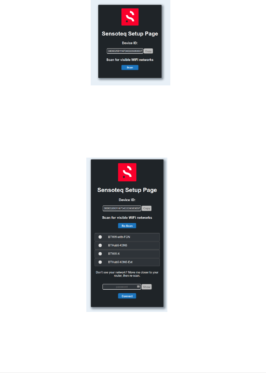
Once loaded the page should look similar to that which is shown in the image below. The device ID
can be ignored; however, this can be useful when contacting Sensoteq support team about
problems configuring a receiver.
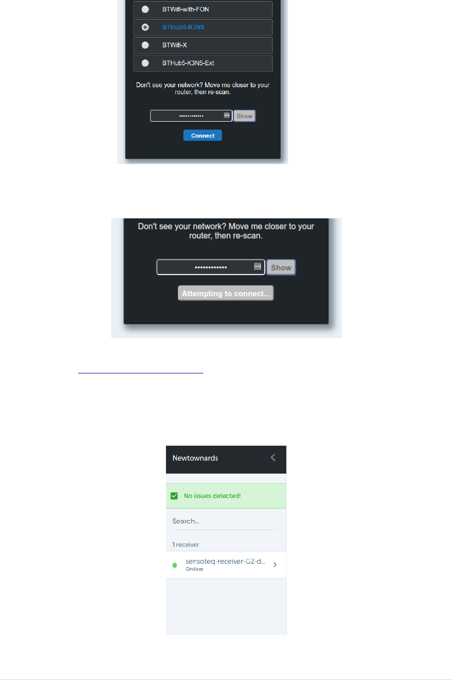
Press Scan to search for a list of available networks and wait for the receiver to produce a list. Once
this loads it may appear as shown below. If you cannot see the network you wish to connect the
receiver to, then re-position the receiver and press re-scan. If you must disconnect the power from
the receiver to re-position it then it will be necessary to start from the beginning.
To complete the process select the network which the receiver will be connected to and enter its
password. The show button can be used to confirm the password is correct. Please note that if the
password is incorrectly please wait a moment and then start from the beginning of this configuration
guide (it will require re-connecting to the receiver’s WiFi network).
7 | P a g e
After pressing connect the page will update to the image shown below and a pop-up will appear to
state that the receiver is attempting to connect.
Finally to confirm that the receiver has successfully connected to the Sensoteq Cloud login to the
Sensoteq HMI at https://world.sensoteq.com and click your location on the map. The receiver
should be shown on the left of the screen with a green dot beside its name as shown in the image
below. If your location does not appear on the map, or the receiver has a red dot then you may need
to check that the receiver has been configured correctly or if the power has been disconnected.
8 | P a g e
3. Sensor Installation
Authorisation from responsible site safety officer must be taken prior to any installation, and
Health and Safety precautions must be taken during installation. We recommend that installation is
performed by qualified Sensoteq personnel or Sensoteq trained personnel.
Appropriate location to mount the sensor should be determined where vibration and/or
temperature is most representative of machine behaviour.
The sensor base is magnetic, and this is the preferred mounting method. Alternative methods can be
used by contacting Sensoteq Technical team. The sensor must be well secured onto the machine to
ensure good transfer of vibration and heat.
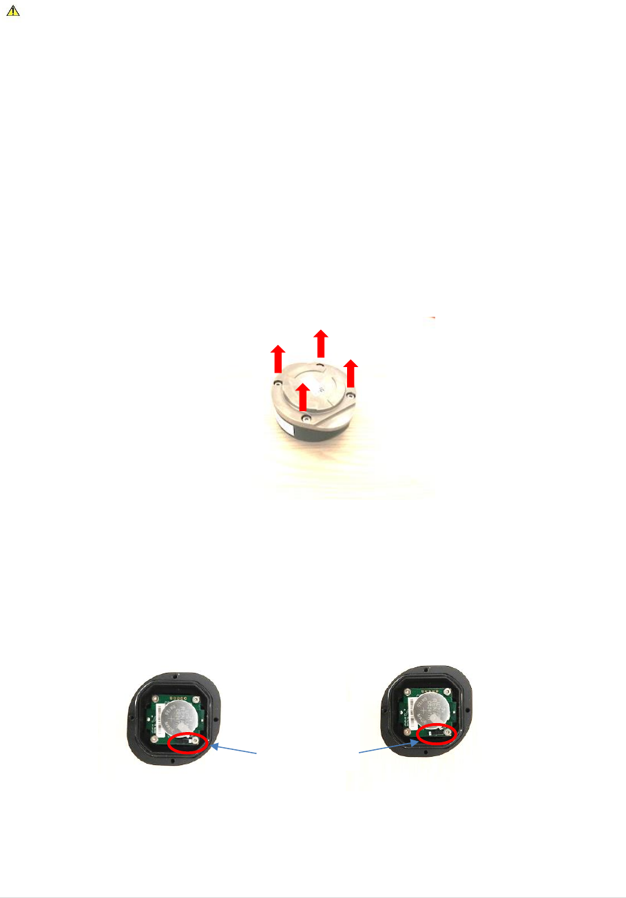
All sensors are turned off in factory mode, and require to be turned on before the first installation.
The sensor can be opened by removing the 4xM3 Screws on the base as shown in the figure below.
Procedure to open the sensor
The switch should be turned on, then the base securely screwed back on.
Procedure to turn the sensor on (Right=OFF, Left=ON)
Screws
Switch
ON OFF
9 | P a g e
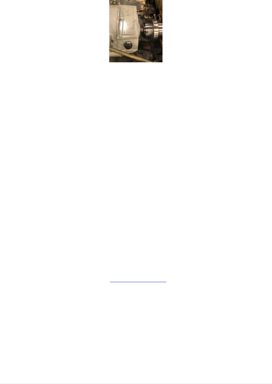
The sensor unique ID (as shown on Sensor label) and its location on the machine should be recorded.
This is then used on the web interface to locate the sensor and display the measured parameters.
Sensor Mounted on Bearing Housing
4. Sensor Modes
When the sensor is turned on, it measures the Temperature and Vibration on regular basis then
transmit the data to the gateway. Both the sampling frequency and transmission rate are
programmable at Sensoteq Factory depending on the application. The minimum sampling time is
10sec in order to preserve the battery lifetime of up to 5 years.
The Sensor can also be set to transmit faster (10sec) during the first 20 minutes of being turned on.
This allows for quick diagnostic during installation.
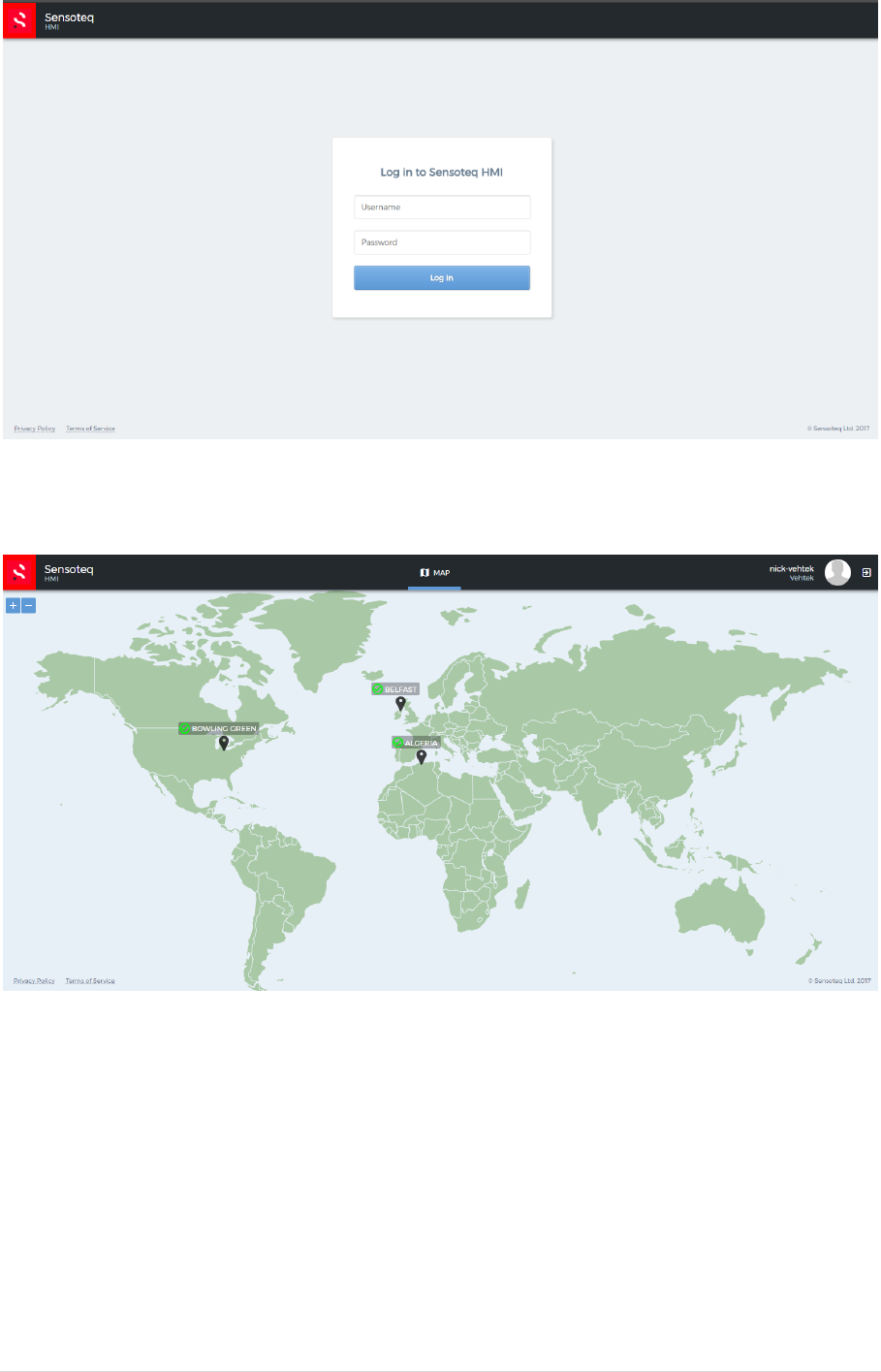
5. HMI
A web interface has been designed in order to setup the system, and monitor the data. This can be
accessed through the Customer login on www.sensoteq.co.uk
In order to use it, a customer has to be setup by the administrator (Sensoteq).
After login, the customer can access all the sites corresponding to his account as shown on the
pictures below
10 | P a g e
Log in Page
World map Sites view
Warning and Alarms can be set through the HMI, and monitored through it. If a warning or an alarm
is present, this will be viewed on the World map site with a colour coded flag (Red = Alarm, Orange =
Warning, Green = No Warning/Alarm)
By Clicking on the site, then on the desired Gateway, the user can visualise all the data monitored by
the sensor.
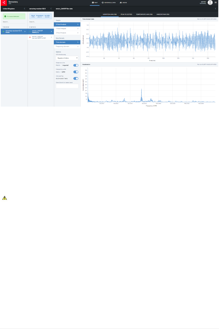
11 | P a g e
Example of Monitored Data displayed on HMI
6. Handling
In order to prevent Sensor Damage, the sensor should not be exposed to Temperature above 80°C
(176°F).
The sensor contains a non-replaceable, not rechargeable Lithium Ion Battery, and should follow
proper procedure for the safe disposal.
If there are any issues with the product please contact Sensoteq Ltd.
Contact Details:
Sensoteq Ltd
Unit 18 Ormeau Business Park
8 Cromac Avenue
Belfast
BT7 2JA
+44 2890 511 259

12 | P a g e