Senstar 24000 Bi-static Microwave Intrusion Detection System User Manual Installation operation guide
Senstar Corporation Bi-static Microwave Intrusion Detection System Installation operation guide
Senstar >
Contents
- 1. Installation and Operating Guide
- 2. I5T14100 Installation and Operating Guide
- 3. I5T16000 Installation and Operating Guide
Installation and Operating Guide

Installation
Series 24000
Bi-static Microwave Intrusion Detection System
& operation
guide
E4DA0202-001, Rev E
First Edition
November 19, 2002

Senstar-Stellar Corporation
119 John Cavanaugh Drive
Carp, Ontario
Canada K0A 1L0
Tel: (613)-839-5572
Fax:(613)-839-5830
Website: www.senstarstellar.com
Email address: info@senstarstellar.com
See back cover for regional offices.
E4DA0202-001, Rev E
First edition
Senstar-Stellar and the Senstar-Stellar logo are registered trademarks of Senstar-Stellar Corporation. Copyright © 2002
Senstar-Stellar Corporation. All rights reserved. Printed in Canada.
The information provided in this guide has been prepared by Senstar-Stellar Corporation to the best of its ability. Senstar-Stellar
Corporation is not responsible for any damage or accidents that may occur due to information about items of equipment or
components not manufactured by Senstar-Stellar Corporation. Features and specifications are subject to change without notice.
FCC Certification: FL924000
This device complies with FCC Rules Part 15. Operation is subject to the following two conditions:
1. This device may not cause harmful interference, and
2. This device must accept any interference that may be received, including interference that may cause undesired operation.
Any changes or modifications not expressly approved by Senstar-Stellar Corporation could void the user’s authority to operate
the equipment.

CUbYUc"$ Y^cdQ\\QdY_^Q^T_`UbQdY_^WeYTUd_S!
Table of contents
1
Overview
- - - - - - - - - - - - - - - - - - - - - - - - - - - - - - - - - - - 1-1
Introduction
- - - - - - - - - - - - - - - - - - - - - - - - - - - - - - - - - - - - - - - - - - - - - - - - - - - - - - - - 1-1
General description
- - - - - - - - - - - - - - - - - - - - - - - - - - - - - - - - - - - - - - - - - - - - - - - - - - 1-1
2
Site planning & design
- - - - - - - - - - - - - - - - - - - - - - - - - - - 2-1
Site preparation
- - - - - - - - - - - - - - - - - - - - - - - - - - - - - - - - - - - - - - - - - - - - - - - - - - - - - 2-1
Site selection
- - - - - - - - - - - - - - - - - - - - - - - - - - - - - - - - - - - - - - - - - - - - - - - - - - - 2-1
CYdUTUcYW^
"#
Zone placement
- - - - - - - - - - - - - - - - - - - - - - - - - - - - - - - - - - - - - - - - - - - - - - - - - 2-3
Zone length
- - - - - - - - - - - - - - - - - - - - - - - - - - - - - - - - - - - - - - - - - - - - - - - - - - - - 2-3
Offsets
- - - - - - - - - - - - - - - - - - - - - - - - - - - - - - - - - - - - - - - - - - - - - - - - - - - - - - - 2-3
3
Installation
- - - - - - - - - - - - - - - - - - - - - - - - - - - - - - - - - - 3-1
Unpacking and inspection
- - - - - - - - - - - - - - - - - - - - - - - - - - - - - - - - - - - - - - - - - - - - - - 3-1
Optional components
- - - - - - - - - - - - - - - - - - - - - - - - - - - - - - - - - - - - - - - - - - - - - - 3-1
Transit damage
- - - - - - - - - - - - - - - - - - - - - - - - - - - - - - - - - - - - - - - - - - - - - - - - - - 3-2
Tools and equipment
- - - - - - - - - - - - - - - - - - - - - - - - - - - - - - - - - - - - - - - - - - - - - - - - - - 3-2
Installation - mechanical
- - - - - - - - - - - - - - - - - - - - - - - - - - - - - - - - - - - - - - - - - - - - - - - 3-3
Mounting units
- - - - - - - - - - - - - - - - - - - - - - - - - - - - - - - - - - - - - - - - - - - - - - - - - - 3-3
Align head-to-head
- - - - - - - - - - - - - - - - - - - - - - - - - - - - - - - - - - - - - - - - - - - - - - - 3-5
Optional wall mounting
- - - - - - - - - - - - - - - - - - - - - - - - - - - - - - - - - - - - - - - - - - - - - - - - 3-5
Determining mounting height
- - - - - - - - - - - - - - - - - - - - - - - - - - - - - - - - - - - - - - - - - - - - 3-6
Chart axis
- - - - - - - - - - - - - - - - - - - - - - - - - - - - - - - - - - - - - - - - - - - - - - - - - - - - - 3-6
Node curves
- - - - - - - - - - - - - - - - - - - - - - - - - - - - - - - - - - - - - - - - - - - - - - - - - - - - 3-6
Installation - electrical
- - - - - - - - - - - - - - - - - - - - - - - - - - - - - - - - - - - - - - - - - - - - - - - - - 3-7
Transmitter wiring
- - - - - - - - - - - - - - - - - - - - - - - - - - - - - - - - - - - - - - - - - - - - - - - - - - - - 3-8
Receiver wiring
- - - - - - - - - - - - - - - - - - - - - - - - - - - - - - - - - - - - - - - - - - - - - - - - - - - - 3-10

dQR\U_VS_^dU^dc
d_S"CUbYUc"$ Y^cdQ\\QdY_^Q^T_`UbQdY_^WeYTU
4
Operating instructions
- - - - - - - - - - - - - - - - - - - - - - - - - - - 4-1
Preliminary check
- - - - - - - - - - - - - - - - - - - - - - - - - - - - - - - - - - - - - - - - - - - - - - - - - - - -
4-1
Channel select switch
- - - - - - - - - - - - - - - - - - - - - - - - - - - - - - - - - - - - - - - - - - - - - - 4-1
Range switch
- - - - - - - - - - - - - - - - - - - - - - - - - - - - - - - - - - - - - - - - - - - - - - - - - - -
4-1
Latch/Timed jumper
- - - - - - - - - - - - - - - - - - - - - - - - - - - - - - - - - - - - - - - - - - - - - - 4-1
Sensitivity jumper
- - - - - - - - - - - - - - - - - - - - - - - - - - - - - - - - - - - - - - - - - - - - - - - - 4-2
Antenna pattern
- - - - - - - - - - - - - - - - - - - - - - - - - - - - - - - - - - - - - - - - - - - - - - - - - 4-2
Electrical alignment
- - - - - - - - - - - - - - - - - - - - - - - - - - - - - - - - - - - - - - - - - - - - - - - 4-3
Sensitivity adjustment
- - - - - - - - - - - - - - - - - - - - - - - - - - - - - - - - - - - - - - - - - - - - - 4-5
5
Troubleshooting
Return for repair procedures
- - - - - - - - - - - - - - - - - - - - - - - - - - - - - - - - - - - - - - - - - - 5-1
Nuisance alarm
- - - - - - - - - - - - - - - - - - - - - - - - - - - - - - - - - - - - - - - - - - - - - - - - - -
5-1
Continuous alarm
- - - - - - - - - - - - - - - - - - - - - - - - - - - - - - - - - - - - - - - - - - - - - - - - 5-1
No alarm
- - - - - - - - - - - - - - - - - - - - - - - - - - - - - - - - - - - - - - - - - - - - - - - - - - - - - -
5-1
Test points
- - - - - - - - - - - - - - - - - - - - - - - - - - - - - - - - - - - - - - - - - - - - - - - - - - - - -
5-2
Appendix a
- - - - - - - - - - - - - - - - - - - - - - - - - - - - - -
Specifications
Appendix b
- - - - - - - - - - - - - - - - - - - - - - - - - - - -
Application notes

CUbYUc"$ Y^cdQ\\QdY_^Q^T_`UbQdY_^WeYTU!!
1
Overview
Introduction
The Series 24000 Microwave Intrusion Detection System is designed for exterior perimeter intrusion detection
applications. The Series 24000 detects movement within a microwave field between the Transmitter and Receiver
and initiates an Alarm to alert responding personnel.
General description
The Senstar-Stellar Microwave Intrusion Detection System consists of a microwave transmitter unit and receiver
unit. Each system is designed to detect motion in a specified area called a detection zone (see Figure 1-1). This
detection zone is established by the transmitter unit sending continuous microwave signals to the receiver unit.
Any motion in this detection zone causes a variation in the received signal strength. These signal variations are
detected by the receiver unit and processed to give an intrusion notification.
The transmitter/receiver unit is mounted in a weatherproof enclosure. Each enclosure contains the respective
electronic circuitry, and may be wired to report attempts of tampering. An antenna is part of each electronic
enclosure. The antenna on the transmitter unit contains the microwave source. The receiver antenna contains the
microwave detector.
This Installation and operation guide is intended for the person(s) who will be doing the initial site layout and
installation of the Series 24000 Microwave Intrusion Detection System. It provides the information required to
install the system, from the time of unpacking shipped equipment to verification of an operational system after
installation. Site preparation, installation procedures, and general theory of operation are covered by this guide.

7U^UbQ\TUcSbY`dY_^
!"CUbYUc"$ Y^cdQ\\QdY_^Q^T_`UbQdY_^WeYTU
Figure 1-1: Series 24000 intrusion detection system
Beam centerline
Detection zone

CUbYUc"$ Y^cdQ\\QdY_^Q^T_`UbQdY_^WeYTU"!
2 Site planning & design
NOTE: Refer to Appendix b, Application notes for additional information on microwave
site planning and design.
Site preparation
The amount and type of site preparation required depends on the level of security desired. The physical
specifications for a high security detection zone are:
•Transmitter/receiver separation distance no longer than 100 m (328 ft.)
•Terrain must be level to grade, ± 7.6 cm (3 in.)
•Terrain finished with crushed rock (2.5 cm {1 in.} max.) to a depth of 10 cm (4 in.) or paved zone completely
void of vegetation
•Transmitter/receiver units mounted 61 cm (24 in.) beam centerline (center of antenna) to ground
When physical properties of the detection zone are not within these parameters, the system capabilities are
diminished. High security applications require much more stringent specifications than do applications where
only a beam-break alarm is required. The following definitions should be used to determine the level of security
required:
High Security Zone - detection of intruder stomach-crawling parallel to the beam.
Medium Security Zone - detection of intruder crawling on hands and knees.
Low Security Zone - detection of a walking intruder, vehicles, etc. (Beam-break alarm only).
Site selection
A physical survey of the intended site is essential. During this survey, all physical features of the site should be
noted. Make accurate distance measurements of the area to be protected and draw a rough sketch. Pictures taken
during this survey are also a valuable aid. Most sites may be used if the following parameters are kept in mind:
Line of sight
A clear, direct line-of-sight between the receiver and transmitter units must be maintained at all times. The sensor
system will work best with a long, flat, detection zone.

CYdUcU\USdY_^
""CUbYUc"$ Y^cdQ\\QdY_^Q^T_`UbQdY_^WeYTU
Movement
Movement of objects (trees, brush, shrubs, etc.) in the detection zone may cause the system to alarm. The
detection zone should not include water, such as lakes, streams or ponds which, if moving, may result in alarms.
Depending on the level of security desired, the presence of wildlife (rabbits, cats, dogs, deer, cows, etc.) may result
in nuisance alarms. The motion of semi-rigid objects (metal buildings, fences, materials, etc.) that are outside the
intended protection zone may produce nuisance alarms if the objects are illuminated by the transmitted
microwave signal.
Depressions
Drainage ditches and gullies should either be avoided or filled in. These depressions could allow undetected
access by an intruder, and periodic water flow will cause nuisance alarms.
Vegetation
Trees, bushes, shrubs, and tall grass within the detection zone will have an adverse effect on the nuisance alarm
rate and on detection probability, especially when this vegetation is wet with rain or dew.
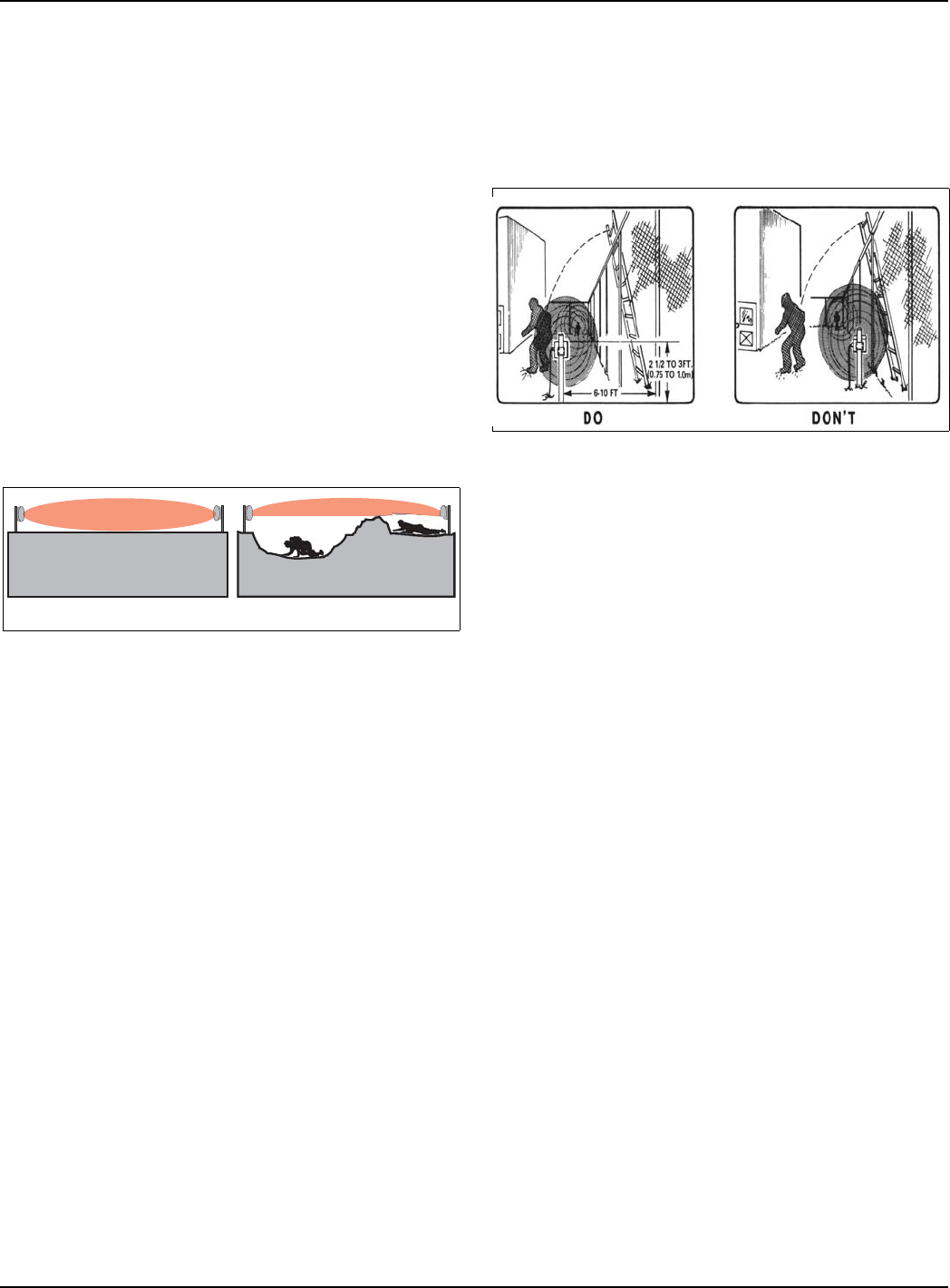
Ground cover
The type of ground cover in the detection zone has several effects on the sensor system:
Crushed rock
This is the optimum type of ground cover for high security applications. Crushed rock will disperse rain drops,
whereas a hard, smooth surface will cause raindrops to bounce, creating movement in the detection zone.
Microwave energy is also reflected off the rocks, increasing the sensitivity of the detection zone. This high
detection zone sensitivity allows the system to have a lower alarm sensitivity. Crushed rock will allow rainwater to
seep into the rocks, preventing it from forming puddles that may cause nuisance alarms.
Paved surface
If the detection zone requires snow removal, then a paved surface is recommended. Accumulated snow will
change the detection characteristics.
Other surfaces
Closely mowed grass (7.6 cm {3 in.} or less) asphalt, concrete and hard-packed clay are satisfactory surfaces for
medium and low security applications.
Terrain
Sharp deviations in terrain within the line-of-sight may result in “holes” in the detection zone. In addition, this may
produce a detection “shadow.” This shadow creates an unmonitored area for entry of an intruder.

CYdUTUcYW^
CUbYUc"$ Y^cdQ\\QdY_^Q^T_`UbQdY_^WeYTU"#
Site design
Detailed site design drawings for the microwave sensor system should be prepared as soon as possible after the
site survey. Dimensions and elevations should be shown on these drawings, as well as the location of the physical
objects noted during the survey. After the site drawings have been completed, the next step is to plot each
microwave zone. Zone placement, zone length, and offsets are essential to the design of a reliable microwave
security system.
Zone placement
The transmitter and receiver units must be mounted with a direct, unobstructed line-of-sight between them. The
suggested minimum distance between the beam centerline and any object that may move (fences, trees, bushes,
shrubs, etc.) is detailed in Table 2-1. Separation distances are based on average conditions and may vary
depending on site conditions, mounting height, type of obstacle, etc.
Zone length
The optimum length of each zone depends on several factors:
•level of security required
•physical constraints (terrain, trees, buildings, etc.)
•space available for the detection zone
The maximum zone length for a low security application is 150 m (492 ft.).
The maximum zone length for a high security application is 100 m (328 ft.).
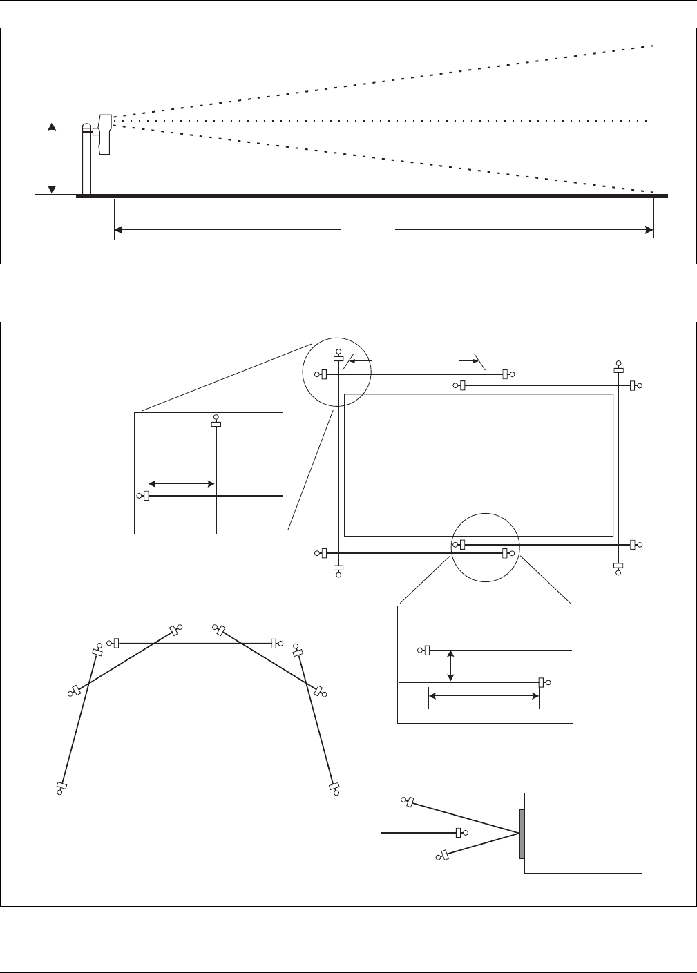
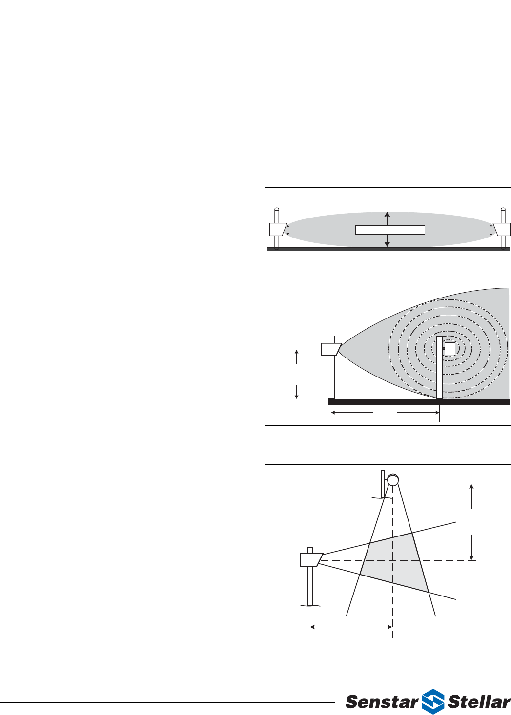
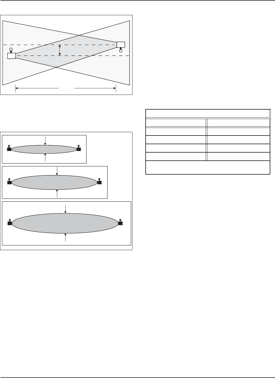
Offsets
The area immediately below the transmitter/receiver antenna is not exposed to the sensor system's microwave
energy. To compensate for this unmonitored area, an offset of the sensor system is required (see Figure 2-1).
Offsets prevent the possibility of intruders crawling under or jumping over a transmitter or receiver unit to gain
access to the protected area. The offset distances are based on the transmitter/receiver mounted at a height of
61 cm (24 in.) (beam centerline to ground). As the mounting height of a transmitter and receiver is increased a
longer offset is necessary. Different types of offsets are shown in Figure 2-2.
NOTE: Medium and low security applications usually require higher mounting heights
and shorter offsets than those required for high security applications.
Zone length
Distance from object (minimum)
91 m (300 ft.)
1.6 m (5.25 ft.)
122 m (400 ft.)
2.1 m (7 ft.)
150 m (492 ft.)
2.7 m (8.75 ft.)
Table 2-1: zone length/object
CYdUTUcYW^
"$CUbYUc"$ Y^cdQ\\QdY_^Q^T_`UbQdY_^WeYTU
Figure 2-1: Offset area
Figure 2-2: Offset arrangements - typical high-security applications
61 cm
(24 in.)
Beam centerline
Offset
4.9 m
(16 ft.)
Detection zone
Secured area
Beam
centerline
Corner offset
61 cm (24 in.) mounting height
Parallel offset
R
R
R
R
T
T
T
T
T
T
R
R
R
R
T
Reflector
Building
Zero offset
61 cm (24 in.) mounting height
T
T
R
R
T
TR
R
T
T
R
R
Basket weave
Zone layout, section
accomodates odd shaped perimeters
4.9 m (16 ft.)
1 m (3 ft. 3 in.)
9.8 m (32 ft.)

CUbYUc"$ Y^cdQ\\QdY_^Q^T_`UbQdY_^WeYTU#!
3Installation
Unpacking and inspection
The Series 24000 Intrusion Detection System is shipped in one carton. Immediately after unpacking, identify all
components and report any shortages to Senstar-Stellar. The components in each carton are as follows:
Transmitter unit
Antenna enclosure assembly. Transmits microwave beam.
Receiver unit
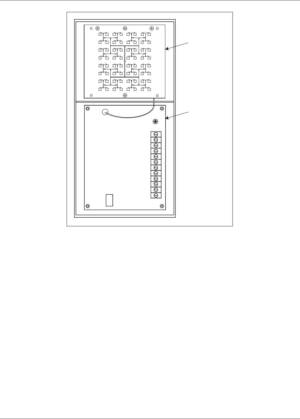
Antenna enclosure assembly (see Figure 3-1). Receives microwave beam.
Mounting hardware
One set per unit. Facilitates mounting transmitter/receiver units to 9 cm (3 1/2 in.) OD post.
Installation and operation guide
Packed in carton.
Optional components
Power distribution box
Provides convenient wiring interface between units and alarm reporting panel. Includes tamper switch and
115 VAC outlet receptacles.
Power supply with standby battery
Plugs in to 115 VAC outlet, provides 2 A continuous power with 5 AH standby battery.

D__\cQ^TUaeY`]U^d
#"CUbYUc"$ Y^cdQ\\QdY_^Q^T_`UbQdY_^WeYTU
Wall mounting brackets
Facilitates mounting the unit directly to a wall.
Transit damage
Although the transmitter and receiver are carefully packed, check for possible transit damage. If any damage has
occurred in shipping, leave the packing carton and components intact and notify your carrier. Senstar-Stellar is not
responsible for shipping damage.
Tools and equipment
Nomenclature
Manufacturer/model
Purpose
digital multimeter
Fluke 8062B
Measure Automatic Gain Control voltage
during initial alignment
wrench, adjustable
common
Mount unit to post and adjust pitch of
units
Screwdriver, slot 15 cm
long x 6 mm wide
(6 in. long x 1/4 in. wide)
common
Connect external leads to unit terminal
board
Screwdriver, slot 10 cm
long x 3 mm wide
(4 in. long x 1/8 in. wide)
common
Adjust sensitivity and alarm duration
Sphere, polished
aluminum 30.5 cm (1 ft.)
with sled
Universal Metal Spinning
Albuquerque, NM 87110
Adjust sensitivity in high-security
applications
9^cdQ\\QdY_^]USXQ^YSQ\
CUbYUc"$ Y^cdQ\\QdY_^Q^T_`UbQdY_^WeYTU##
Installation - mechanical
Mounting units
Both the transmitter and receiver units must be securely mounted to prevent movement or vibration. Excessive
movement or vibration of either units will cause nuisance alarms. Windy conditions are a potential problem if the
units are not mounted properly. Refer to Figure 3-2 for a visual overview of the following instructions.
Set post
The transmitter and receiver units have been designed to mount on a 9 cm (3 1/2 in.) OD post. A 2.44 m (8 ft.)
post is typically used with 91 cm (3 ft.) of the post buried in a concrete footing.
NOTE: Mounting posts are not included.
Figure 3-1: Series 24000 microwave unit (receiver)
TB1
TAMPER
SWITCH
J3
Antenna
Electronic PCB
(receiver unit)
9^cdQ\\QdY_^]USXQ^YSQ\
#$CUbYUc"$ Y^cdQ\\QdY_^Q^T_`UbQdY_^WeYTU
Foundation
The foundation for the mounting posts in normal soil should be at lease 91 cm (3 ft.) deep and 61 cm (2 ft.) in
diameter. If soil conditions are such that a non-shifting foundation is questionable, then a larger footing should be
considered. In areas where extremely low temperatures may cause frost heaving, use a truncated pyramid base
foundation.
Rebar
When the foundation concrete cures, there is a possibility of it pulling away from the post, allowing for rotation of
the mounting post. Placement of rebar below ground level in the foundation and through the post is suggested to
prevent this.
Power supply hook-up
A weatherproof junction box in the vicinity of each unit's mounting post is the best location for terminating the
primary power supply. A double-row terminal block allows this to become a convenient junction box for those
lines running back to an alarm reporting panel. Conduit for the power supply junction box should be installed in
the foundation as illustrated in Figure 3-2. Be sure to mount the junction box so that it will not interfere with the
antenna enclosure, and is not in the microwave beam.
Transmitter/Receiver
Mount the transmitter and receiver units on their respective posts, using the pipe clamps and hardware provided.
The mounting height of the transmitter and receiver units is measured from the center of the antenna to ground.
Refer to Determining mounting height on page 3-6 for the approximate mounting height of the microwave units.
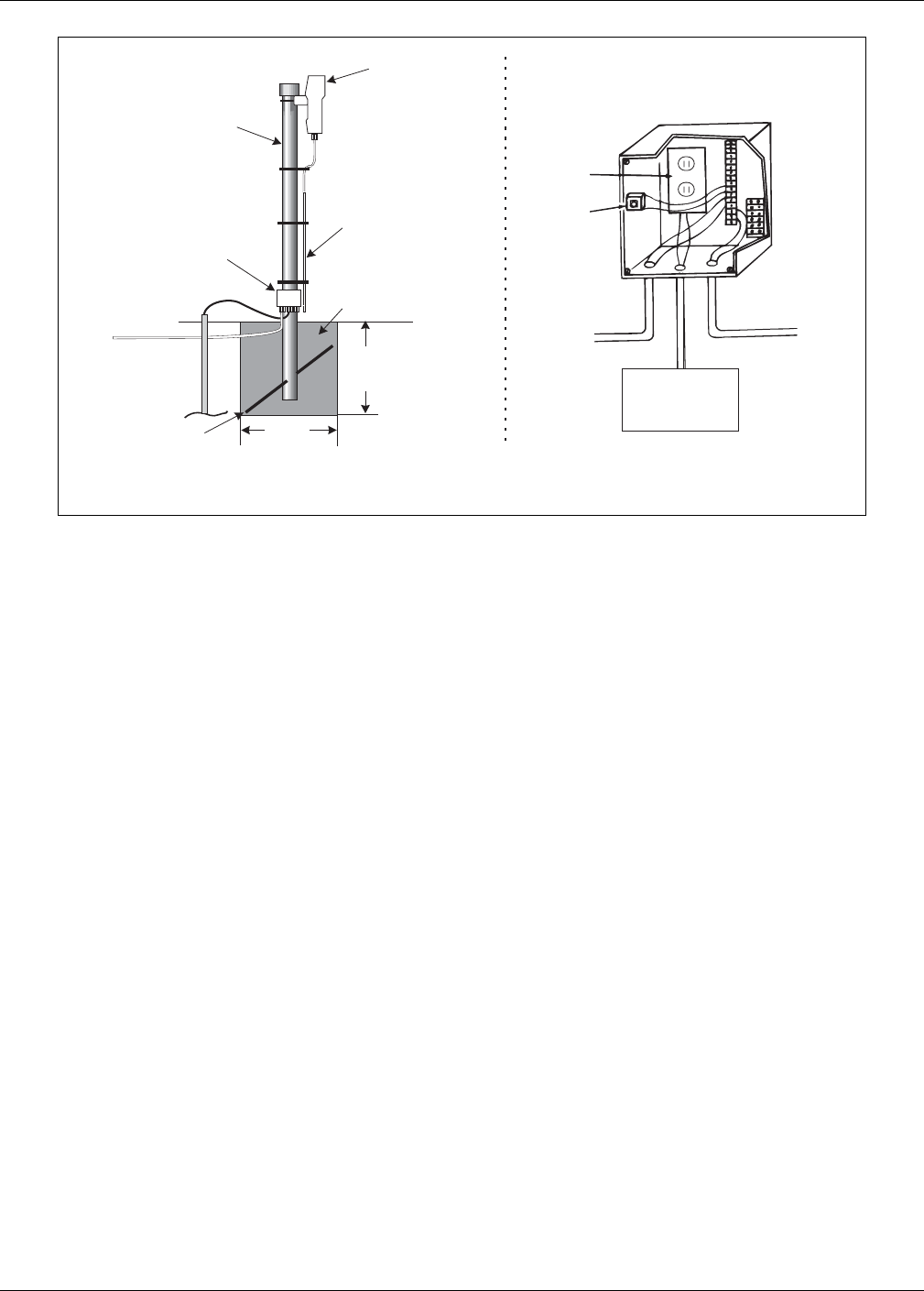
Figure 3-2: Post installation and unit mounting
Series 24000 unit
weatherproof
junction box
concrete
footing
buried conduit
to alarm panel
& power supply
rebar
through pipe
9 cm (3.5 in.)
steel pipe
typically 2.4 m
(8 ft.) long
power
supply
plug-in
tamper
switch
to alarm
reporting
panel to transmitter
or reciever
weatherproof
junction box detail
(optional)
primary power
source & earth
ground wire
91 cm *
(3 ft.)
61 cm
(2 ft.)
ground wire
ground rod
*
Consult the local construction codes for information about installing
concrete footings in environments where ground freezing occurs.
U
power, ground
and alarm wiring
in conduit to
microwave unit

9^cdQ\\QdY_^]USXQ^YSQ\
CUbYUc"$ Y^cdQ\\QdY_^Q^T_`UbQdY_^WeYTU#%
Transmitter/Receiver grounding
Connect a ground wire(s) to a properly installed ground rod. Connect the ground wire(s) to the appropriate
terminal(s) on the Transmitter/Receiver PCB. (Refer to Figures 3-4 and 3-5 for wiring diagrams of the Transmitter
and Receiver circuitry.)
NOTE: Senstar-Stellar recommends using a low resistance (5 Ω
or less) earth ground
connection at each unit. Consult the local electrical codes for additional
grounding information.
Conduit
1.3 cm (1/2 in.) flexible conduit should be used to run connections to and from the transmitter/receiver units and
power supply junction box. Allow enough slack in this flexible conduit to provide a “drip loop” and vertical
movement of ± 46 cm (18 in.).
NOTE: Conduit and conduit fittings are not included.
Align head-to-head
Physically point the transmitter and receiver toward each other and slightly tighten the clamp nuts so the units will
not fall. Loosen the two nuts on either end of the bracket, and aim the units (in the pitch axis) toward each other.
Slightly tighten the two nuts.
NOTE: This is a preliminary mechanical alignment only. A more precise electrical
alignment will be accomplished as part of the Operating instructions procedure.
Optional wall mounting
NOTE: When using the optional wall mount bracket, disregard references to post
mounting, and follow these instructions.
1. Power the units up by following the Installation - electrical instructions. This power may be temporary (batteries).
2. Using the mounting height chart, Figure 3-3, determine the approximate mounting height of the units.
3. Follow the Operating instructions to ensure the units are functioning correctly. Connect a digital voltmeter to TP-10
(AGC Voltage) on the receiver. Move the “LATCH - TIMED” jumper to the “LATCH” position to speed up the
AGC response.
4. Slowly move both units vertically up and down from the nominal mounting height determined from Figure 3-3. The
optimum mounting height is reached when the digital voltmeter reading is the highest. Mark the spot on the wall and
attach the wall mount to the wall.
5. Attach the units to the mounts.

4UdUb]Y^Y^W]_e^dY^WXUYWXd
#&CUbYUc"$ Y^cdQ\\QdY_^Q^T_`UbQdY_^WeYTU
Determining mounting height
The mounting height chart (Figure 3-3) is used to determine the best theoretical mounting height of the
transmitter/receiver units for optimum efficiency of the sensor system. This height chart is intended to furnish a
preliminary mounting height only. The final operating height will be determined during electrical alignment and
final adjustment.
Chart axis
The horizontal axis of the height chart represents the distance between the transmitter and receiver units. The
vertical axis represents the mounting height of the transmitter/receiver units from the center of the antenna to the
ground.
Node curves
The node curves (N1, N2, N3, N4, N5 and N6) represent the pivot point for coordinating distance (horizontal axis)
to mounting height (vertical axis). Those mounting height and distance coordinate lines that meet in the area
between the node curves should be avoided. Coordinate lines that meet on the node curves are preferred because
they will result in higher signal strength at the receiver and a wider fade margin. However, choosing a mounting
height at N1 or below will also allow satisfactory system operation.
Example:
The distance between the transmitter and receiver is 84 m (275 ft.). Locate this distance on the height chart's
horizontal axis. Plot a vertical line from this distance point across the node curves. These height measurements
represent the best theoretical mounting heights for this example. They are 51 cm (20 in.) or less for the N1 curve
and below, 91 cm (36 in.) for the N2 curve, 114 cm (45 in.) for the N3 curve, etc.
9^cdQ\\QdY_^U\USdbYSQ\
CUbYUc"$ Y^cdQ\\QdY_^Q^T_`UbQdY_^WeYTU#'
Installation - electrical
Power supply
A power source of 12 VDC (11 to 15 VDC) is required by both the transmitter and receiver units. It is
recommended that primary power be brought to the base of each unit's mounting post and terminated in a
weatherproof enclosure. This weatherproof enclosure may then be used as a convenient junction box between the
transmitter and receiver, the primary power, and the alarm reporting panel. 115 VAC power must not be brought
into the enclosures of either the transmitter or receiver units. Refer to Installation - mechanical for installation of a
junction box to house the primary power supply.
Figure 3-3: Mounting height chart
Mounting
height
Unit separation
cm inches cminches
feet
meters
N6
N5
N4
N3
N2
N1

DbQ^c]YddUbgYbY^W
#(CUbYUc"$ Y^cdQ\\QdY_^Q^T_`UbQdY_^WeYTU
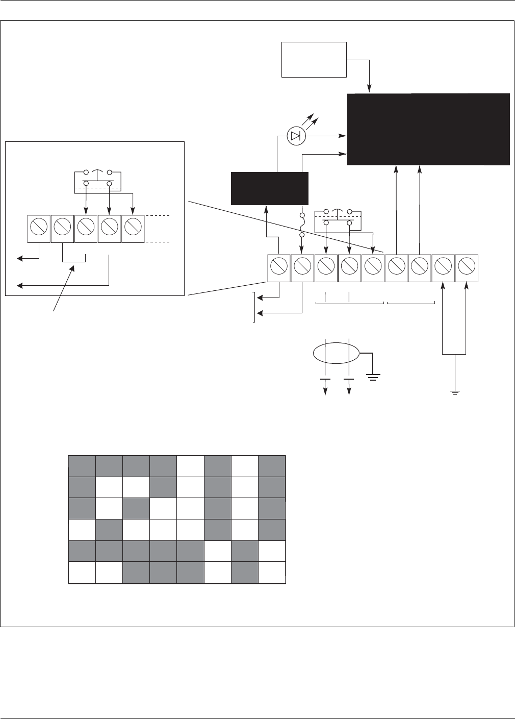
Transmitter wiring
Refer to Figure 3-4 for a wiring diagram of the transmitter unit. It is suggested that an installation wiring diagram
be made before wiring the transmitter. This will standardize the wiring of transmitters in a multiple system
installation.
Power source
Terminals 1 and 2.
The transmitter requires 12 VDC (11 - 15 VDC) to operate. Terminal 1 is negative, terminal 2 is positive.
Tamper reporting
Terminals 3, 4 and 5
The 12 VDC power supply to the transmitter may be connected so that when the electronic enclosure is opened,
the transmitter is disabled and the receiver goes into constant alarm. To have a specific tamper alarm report, wire
the tamper reporting signal directly onto Terminals 3 & 4 or 4 & 5, and wire power directly to Terminals 1 and 2.
Use a twisted/shielded pair of 18 AWG wire for the tamper signal wiring. This wire should be run from the dry
contact tamper output terminals to the junction box, and on to the alarm reporting panel.
Junction box
A tamper switch installed in the power supply junction box may also be wired for tamper reporting. This is done in
conjunction with the electronic enclosure tamper wiring and both are connected to the alarm reporting panel.
Remote self test
Te rm i n al 6 o r 7 .
The transmitter is capable of providing a test signal that will dynamically test the detection zone to the sensitivity
required of that zone. This capability can be remotely activated by applying a +5 to +15 VDC voltage at terminal 6
of the terminal board, or by applying a ground to terminal 7 of this terminal board. A shielded 18 AWG wire should
be used for this connection regardless of the self test actuation method used.
Transmitter ground connection
Connect TB1 terminal(s) 8/9 to a properly installed ground rod.
NOTE: Senstar-Stellar recommends using a low resistance (5 Ω
or less) earth ground
connection at the transmitter unit. Consult the local electrical codes for additional
grounding information.
CAUTION:
When using one DC power supply to power more than one system,
insure the wiring between the power supply and the unit is
sufficient to prevent the input voltage at the unit from dropping
below 11 VDC, when the receivers are not in alarm (maximum
current draw).
DbQ^c]YddUbgYbY^W
CUbYUc"$ Y^cdQ\\QdY_^Q^T_`UbQdY_^WeYTU#)
Figure 3-4: Transmitter wiring
12345
67 89
-+
12 VDC
Input
power
COM 0
VDC
N/C N/O 5-15
VDC
Tamper
(untampered
condition)
Test
signal
enable
Power ON LED
Power
conditioning
Channel
select
switch
Transmitter
circuitry
FUSE
F-1
.25 A
Separate
tamper
reporting
12345
-+COMN/C N/O
-
+
12 VDC
Jumper
installed
by user
345 678
2
Switch number (S3)
1
Channel A
Channel B
Channel C
Channel D
Channel E
Channel F
Channel select Dip Switch settings.
Shaded square indicates switch on.
9521 Hz
10914 Hz
12094 Hz
13161 Hz
14435 Hz
15981 Hz
Tamper
switch
Tamper
switch
connect terminal(s) 8/9
to a properly installed
ground rod

BUSUYfUbgYbY^W
#! CUbYUc"$ Y^cdQ\\QdY_^Q^T_`UbQdY_^WeYTU
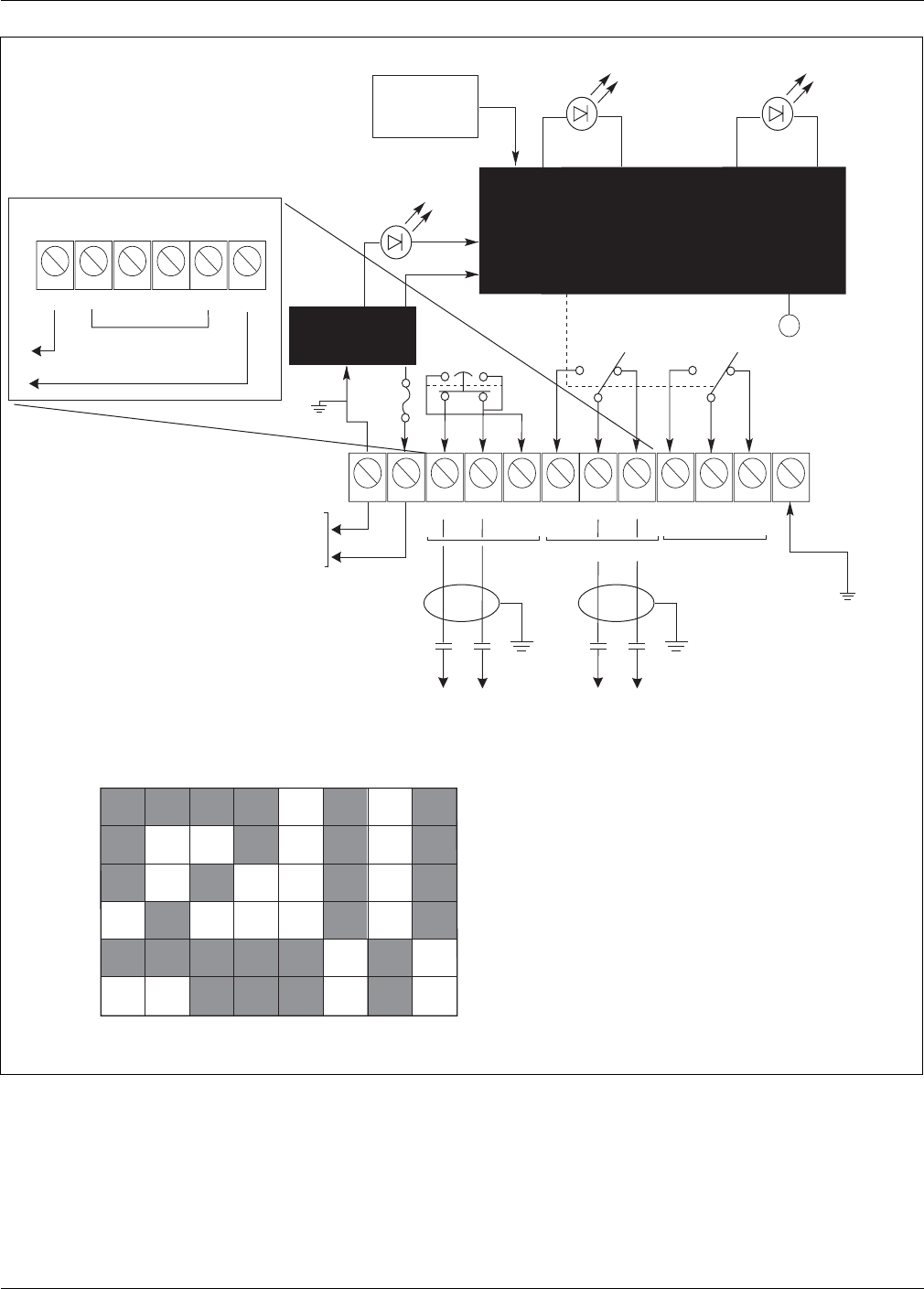
Receiver wiring
Refer to Figure 3-5 for a wiring diagram of the receiver unit. It is suggested that an installation wiring diagram be
made before wiring the receiver. This will standardize the wiring of receivers in a multiple system installation.
Power source
Terminals 1 and 2.
The receiver unit requires 12 VDC (11 to 15 VDC). Terminal 1 is negative, terminal 2 is positive.
Tamper reporting
Terminals 3, 4 and 5.
Non-Specific alarm (series tamper alarm)
You may wire the receiver tamper switch (terminals 3 & 4 or 4 & 5) in series or parallel (depending on alarm relay
logic) with the alarm contacts for a non-specific alarm report. A non-specific alarm report does not indicate
whether an alarm was caused by intrusion detection or tampering with the unit electronic enclosure. A twisted/
shielded pair of 18 AWG wire should be used for this connection.
Specific tamper reporting
To have a specific tamper alarm report, wire the tamper reporting signal directly onto Terminals 3 & 4 or 4 & 5. Use
a twisted/shielded pair of 18 AWG wire for the tamper signal wiring. This wire should be run from the dry contact
tamper output terminals to the junction box, and on to the alarm reporting panel.
Alarm circuit
Terminals 6, 7, 8, 9, 10, and 11.
There are two sets of normally open and normally closed dry relay contacts. One set may be used for alarm
annunciation at the alarm reporting panel. The other could be used for local annunciation, zone certification
testing, etc. Use a twisted/shielded pair of 18 AWG wire to connect the alarm notification to the junction box and
alarm reporting panel.
Multipath sidetone
Phono plug adjacent to Terminal 12.
This is an audio output (2 mW, 600Ω
) whose frequency and amplitude are proportional to the amount and location
of a source of motion within the detection zone. It can be used as a local test signal, or can be amplified and
connected to the alarm monitoring system. Shielded 18 AWG audio wire should be used to connect this signal to
the annunciator. A phono jack adapter and an amplified speaker can be connected to the phono plug and used as
an aid in aligning the system.
Receiver ground connection
Connect TB1 terminal 12 to a properly installed ground rod.
NOTE: Senstar-Stellar recommends using a low resistance (5 Ω
or less) earth ground
connection at the receiver unit. Consult the local electrical codes for additional
grounding information.
BUSUYfUbgYbY^W
CUbYUc"$ Y^cdQ\\QdY_^Q^T_`UbQdY_^WeYTU#!!
Figure 3-5: Receiver wiring
12345
67 89
-+
12 VDC
Input
power
COM
N/C N/O
Tamper
Power
ON LED
Power
conditioning
Channel
select
switch
Receiver
circuitry
FUSE
F-1
0.5 A
Alarm reporting panel
Tamper
switch
345 678
2
Switch number (S3)
1
Channel A
B
C
D
E
F
Channel
Channel
Channel
Channel
Channel
Channel select Dip Switch settings.
Shaded square indicates switch on.
10 11 12
Wrong
channel
LED
Alarm
LED
N/CCOMN/O
Alarm 1
N/O N/CCOM
Alarm 2
Alarm
34 67 8
COMN/C N/O N/CCOMN/O
5
Series Alarm and Tamper
Multipath
sidetone
output
J3
9521 Hz
10914 Hz
12094 Hz
13161 Hz
14435 Hz
15981 Hz
Separate alarm
and tamper reporting
connect terminal 12
to a properly installed
ground rod

CUbYUc"$ Y^cdQ\\QdY_^Q^T_`UbQdY_^WeYTU$!
4
Operating instructions
Once the following preliminary check, alignment, and sensitivity adjustments are accomplished, the Series 24000
Intrusion Detection System is ready to operate. There are no controls or indicators for operating the sensor
system, and no alternate operating modes during emergency conditions.
Preliminary check
Once the sensor system is mounted and wiring installation completed, a preliminary check, channel selection, and
antenna pattern selection is required before applying power to the system.
Channel select switch
Refer to the Channel Selection Matrix Chart on the Receiver and Transmitter Wiring illustrations. The channel
select switch on each transmitter/receiver pair must be set to the same operating channel. See Figure 3-4
(transmitter) or 3-5 (receiver) for proper settings.
Range switch
This is a small jumper on the receiver circuit board located by the coax input from the antenna. Put this jumper in
the “S” position for separation distances of less than 30.5 m (100 ft.); use the “L” position for ranges greater than
30.5 m (100 ft.).
Latch/Timed jumper
This is a white jumper wire located adjacent to terminals 9, 10 & 11 on the receiver circuit board. When the
jumper is in the TIMED position, the alarm duration is controlled by the setting of R76 DURATION, which is user-
adjustable between 0.5 and 10 seconds.
In the LATCH position, once the system goes into alarm, it will stay in alarm until the jumper is moved to the
TIMED position. This jumper must be in the TIMED position for normal operation; the LATCH position is used
during electrical alignment of the system.

@bU\Y]Y^QbiSXUS[
$"CUbYUc"$ Y^cdQ\\QdY_^Q^T_`UbQdY_^WeYTU
Sensitivity jumper
The position of the Sensitivity Jumper is determined by the application requirements:
•L = Low Security
•M = Medium Security
•H = High Security
(See page 2-1 for definitions of these terms.)
This jumper effectively reduces the maximum alarm sensitivity, preventing excessive sensitivity that may result in
nuisance alarms.
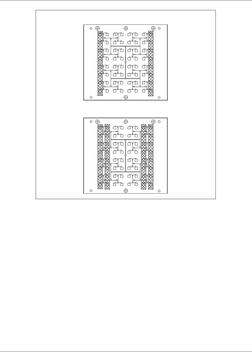
Antenna pattern
The detection pattern is adjustable by use of the sensitivity adjustment, and by changing the configuration of the
transmitting and receiving antennas. The antenna configuration is changed by installing RF absorbent pads over
selected antenna elements (see Figure 4-1). When no antenna pads are installed, the microwave beam is narrowest
(7º). With sixteen of the elements covered, the beam is 11º. With thirty-two of the elements covered, the pattern is
16º. In general, the wide pattern should only be used when the separation distance between receiver and
transmitter is 15 m (50 ft.) or less. The medium range pattern should be used (if necessary) with separation
distances of between 15 m (50 ft.) and 30.5 m (100 ft.). The narrowest pattern (unmodified antenna) must be used
when the separation distance is greater than 30.5 m (100 ft.).
NOTE: Always use the narrowest beam possible, commensurate with detection
requirements.
Install the absorbent pads on both the receiver and transmitter pair in accordance with the following instructions:
1. Select the number of strips of double-backed tape that will cover the elements necessary to provide the desired
detection pattern. Remove the paper backing, and stick the tape over the elements to be covered.
Note: Cover only the elements shown in the illustration (Figure 4-1).
2. Remove the other piece of paper backing from the tape, and firmly press the RF absorbent material to it.
3. Ensure that both the transmitting antenna and the receiving antenna configurations are identical.
@bU\Y]Y^QbiSXUS[
CUbYUc"$ Y^cdQ\\QdY_^Q^T_`UbQdY_^WeYTU$#
Electrical alignment
An electrical alignment requires the antennas of both the transmitter and receiver units to be aimed head-to-head.
Verify initial mechanical alignment. Once this initial mechanical alignment is done, a more precise electrical
alignment is required.
NOTE: The transmitter/receiver units should never be aimed into the ground or off to the
side of the detection zone. However, discontinuities in the detection zone may
dictate an alignment slightly off head-to-head.
NOTE: During this alignment procedure, place the LATCH/TIMED jumper on the receiver
circuit board in the LATCH position. This will speed up the response time of the
AGC voltage to make the adjustment easier.
Figure 4-1: Antenna patterns
Antenna with 16 patches covered (11 )º
Antenna with 32 patches covered (16 )º

@bU\Y]Y^QbiSXUS[
$$CUbYUc"$ Y^cdQ\\QdY_^Q^T_`UbQdY_^WeYTU
AGC measurement
At the receiver, connect a digital voltmeter between TP-10 (+) and TB1-1 (-). This is the automatic gain control
(AGC) voltage. After final alignment, as outlined below, the AGC voltage should be between 1.7 and 7.3 VDC. Put
the SHORT-LONG jumper in the LONG position to increase the AGC voltage. Put the SHORT-LONG jumper in the
SHORT position to decrease the AGC voltage.
Receiver
Slowly move the receiver unit up and down the post while monitoring the receiver AGC voltage. Once a maximum
AGC voltage is obtained, rotate the receiver until maximum AGC is obtained on this axis. Tilt the receiver antenna
up and down, again adjusting for maximum AGC voltage.
Transmitter
Continue to monitor the AGC voltage at the receiver while moving the transmitter in all three axes as described for
the receiver, until maximum AGC voltage is obtained.
Final alignment
Before securing the hardware, repeat the transmitter and receiver unit electrical alignment steps for obtaining
maximum AGC reading on all rotational axes.
Secure hardware
Secure the mounting nuts and bolts. Ensure the AGC voltage remains high while this hardware is tightened. If the
final AGC voltage is greater than 4.0 volts, put the SHORT-LONG jumper in the SHORT position; this will reduce
the voltage to the 2.5 to 3.0 volt range. Put the LATCH/TIMED jumper into the TIMED position for normal
operation.

@bU\Y]Y^QbiSXUS[
CUbYUc"$ Y^cdQ\\QdY_^Q^T_`UbQdY_^WeYTU$%
Sensitivity adjustment
Before beginning a sensitivity adjustment, make sure the receiver “ALARM” LED is not lit. Connect an ohmmeter
between TB1 - terminals 10 and 11. It will read less than 0.5 ohms when the system is operational (armed) and
infinity when the unit is in alarm. Leave the ohmmeter connected.
Alarm test
A preliminary alarm test requires walking across the detection zone to ensure the unit goes into alarm (“ALARM”
LED lit, ohmmeter to infinity). If it does not, adjust the sensitivity potentiometer (R55) clockwise; then walk test
the zone again. An alarm report should normally occur before a line of sight between the transmitter and receiver
units is broken by the walker.
Final alarm test
Determine the level of security sensitivity desired, and then use the following parameters for ensuring that the
level desired is present:
NOTE: Start with the sensitivity jumper in the “L” position - change to “M” or “H” if
unable to get the required detection with adjustment of R55 alone. The final
adjustment setting should be the lowest setting possible that provides the required
detection.
Low security - walk across detection zone in every area intrusion concern is present. Adjust R55 for consistent
detection.
Medium security
- crawl on hands and knees in all detection zone areas of intrusion concern. Adjust R55 for
consistent detection.
High security - pull metal sphere (see Tools on page 3-2); pull often enough to give confidence that the zone has
the sensitivity you want.
High security
Adjustment for a typical high security application requires the detection of a prone human crawling through the
detection zone with the length of the body parallel to the line of sight. A 30.5 cm (12 in.) metal sphere represents
approximately the same target to the microwave sensor. When adjusting the sensitivity to high security
specifications, slowly (13 cm {5 in.} per second or faster) pull the sphere through the zone (perpendicular to the
line of sight) approximately every 3 m (10 ft.) and adjust the sensitivity potentiometer (R55) until repeatable
detection is obtained.
NOTE: Dragging the sphere in the offset area is not necessary.

CUbYUc"$ Y^cdQ\\QdY_^Q^T_`UbQdY_^WeYTU%!
5Troubleshooting
The following are procedures for troubleshooting the Series 24000 Intrusion Detection System. If, after checking
out these conditions, you find your system is still not functioning, then the possibility of a faulty condition on
another system on the premises besides the Series 24000 is very likely.
Return for repair procedures
A Return Material Authorization number (RMA) must be obtained from Senstar-Stellar before any items will be
accepted for return. Please contact Senstar-Stellar Customer Service to obtain this authorization.
When contacting Customer Service, you will need your Model number, Serial number, and the date of purchase.
Please have this information available before you make your request for return.
Nuisance alarm
Nuisance alarms are usually attributed to physical problems within the detection zone. Refer to the Site planning &
design section of the guide, and review the conditions inherent to causing nuisance alarms. If these alarms persist,
note time and conditions of each alarm - is there a physical feature of your detection zone that occurs at certain
times, i.e., traffic or train going by, etc.?
Continuous alarm
Continuous alarms are more likely to be an equipment-related problem than a detection zone problem. First,
determine if the sensor system is aligned and adjusted for appropriate sensitivity. Refer to the Operating
instructions section of the guide, and review the conditions causing continuous alarms. Check to make sure the
alarm relay LATCH/TIMED jumper (white wire) is in the “TIMED” (T) position. Remove external wires from the
receiver unit circuit board terminal 6 or 8, and measure ohms on the relay contact. Then, proceed to Board level
test points on page 5-2, and test the transmitter/receiver circuit boards.
An “alarm” situation may also occur if power to the system is being interrupted. Check both the primary power
source and all terminal connections for the DC power.
No alarm
Check the alarm relay to verify it is working. Remove external wires from the receiver unit circuit board terminal 6
or 8, and measure ohms on the relay contact. Also check the receiver circuit board with the test points listed in the
Board level test points.

Troubleshooting
%"CUbYUc"$ Y^cdQ\\QdY_^Q^T_`UbQdY_^WeYTU
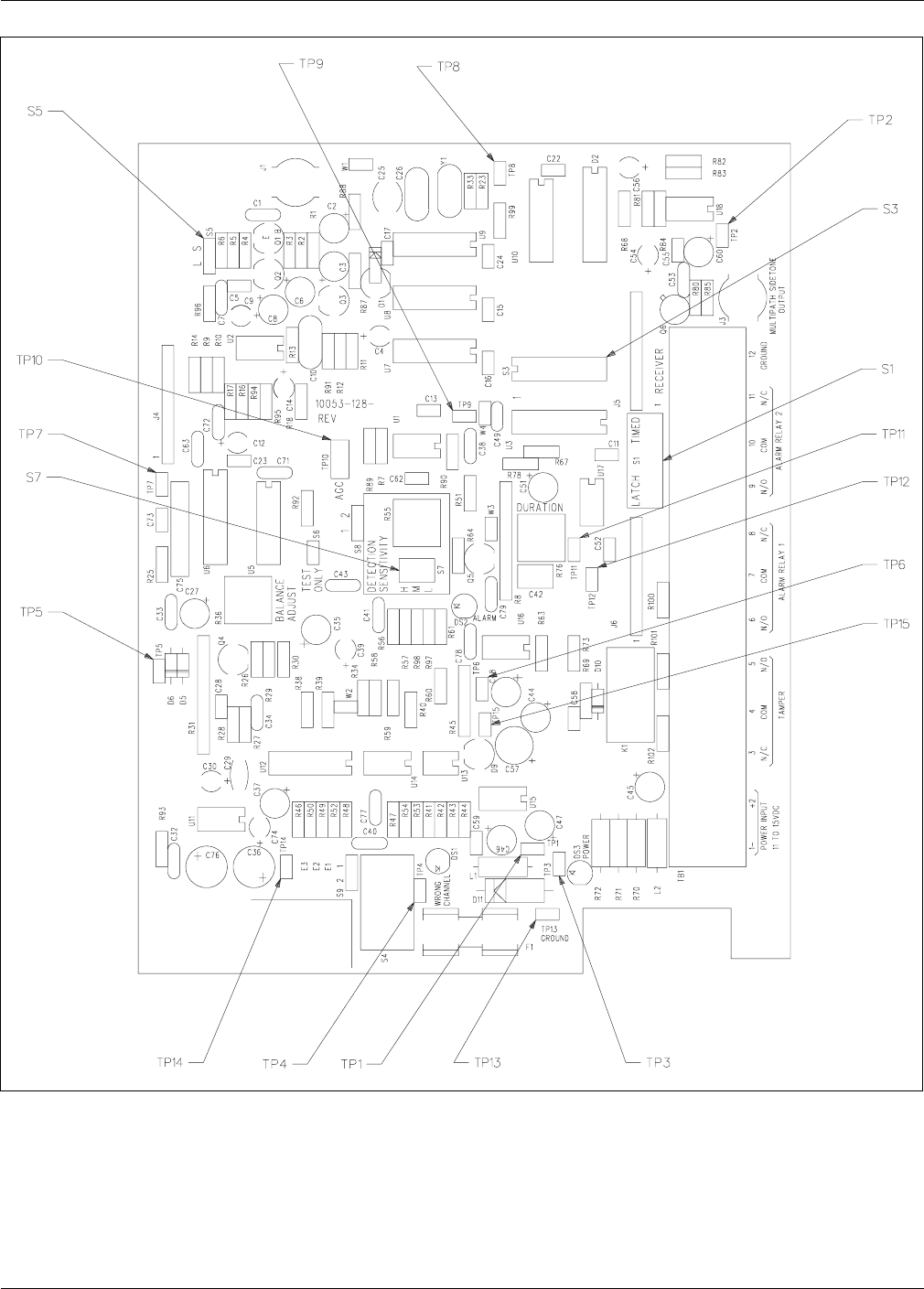
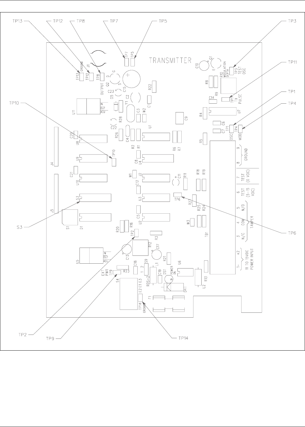
Test points
The boards containing the electronic circuitry in the transmitter/receiver unit enclosures may be tested for
readings required for normal operation of the system. Figures 5-1 (receiver) and 5-2 (transmitter) show the
location of the test points on the boards. These tests should be done under the following conditions:
1. 12 VDC (nominal) power applied to both transmitter and receiver units.
2. The same channel selection for both transmitter and receiver.
3. Mechanical (transmitter to receiver) alignment complete.
4. Obtain “normal indication” for each test/observation before proceeding to the next test point.
5. All measurements require a digital multi-meter (DMM) except where an oscilloscope reading is indicated.
Board level test points
Test point observation
Normal indication
Cause for abnormal reading
Transmitter:
TP-9
11.6 VDC ± 0.25 (@ 12 VDC input)
1. Fuse F1 blown
2. No power to TB-1 terminals
1 (-) and 2 (+), (11 - 15 VDC)
Power LED (DS-1)
Illuminated
1. LED open
2. Voltage regulator U5 open
TP-5
6.0 VDC ± 0.5
Voltage regulator U11 faulty
TP-8
5 - 8 V P-P Oscilloscope reading
(clean and symmetrical square
wave)
1. Power amplifier faulty
2. Code generator faulty
Receiver:
TP-1
11.6 VDC ± 0.25 (@ 12 VDC input)
1. Fuse F1 blown
2. No power to TB-1 terminal 1 (-) and 2
(+), (11 - 15 VDC)
TP-3
5.0 VDC ± 0.1
1. Regulator U15 failure
2. DS-3 Power LED open
TP-2
8.0 VDC ± 0.1
Regulator U15 failure
TP-4
2.5 VDC ± 0.1
Zener diode D9 failure
TP-10
1.7 - 7.3 VDC
1. Channel selection not correct
2. Mechanical alignment improper
3. Transmitter not operating properly
4. Receiver circuits faulty
Alarm LED (DS-2)
Non-illuminated
1. Channel selection not correct
2. Mechanical alignment improper
3. Transmitter not operating properly
4. Receiver circuits faulty
Wrong channel LED (DS-1)
Non-illuminated
1. Channel selection at Tx/Rx not identical
2. Object in path
3. Faulty transmitter
4. Faulty receiver
Table 5-1: test point readings
Troubleshooting
CUbYUc"$ Y^cdQ\\QdY_^Q^T_`UbQdY_^WeYTU%#
Figure 5-1: Receiver PCB
(LATCH/TIMED
jumper)
(SENSITIVITY jumper)
(SHORT/LONG
jumper)
(CHANNEL SELECT
switch)
Troubleshooting
%$CUbYUc"$ Y^cdQ\\QdY_^Q^T_`UbQdY_^WeYTU
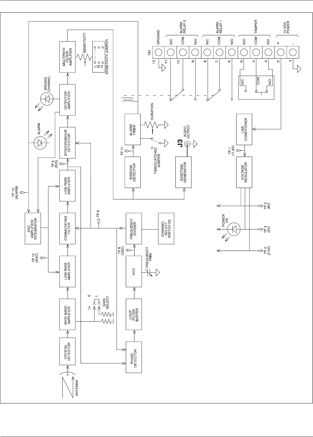
Figure 5-3 is a functional block diagram of the Series 24000 receiver unit.
Figure 5-2: Transmitter PCB
(CHANNEL SELECT
switch)
Troubleshooting
CUbYUc"$ Y^cdQ\\QdY_^Q^T_`UbQdY_^WeYTU%%
Figure 5-3: Receiver block diagram
Troubleshooting
%&CUbYUc"$ Y^cdQ\\QdY_^Q^T_`UbQdY_^WeYTU
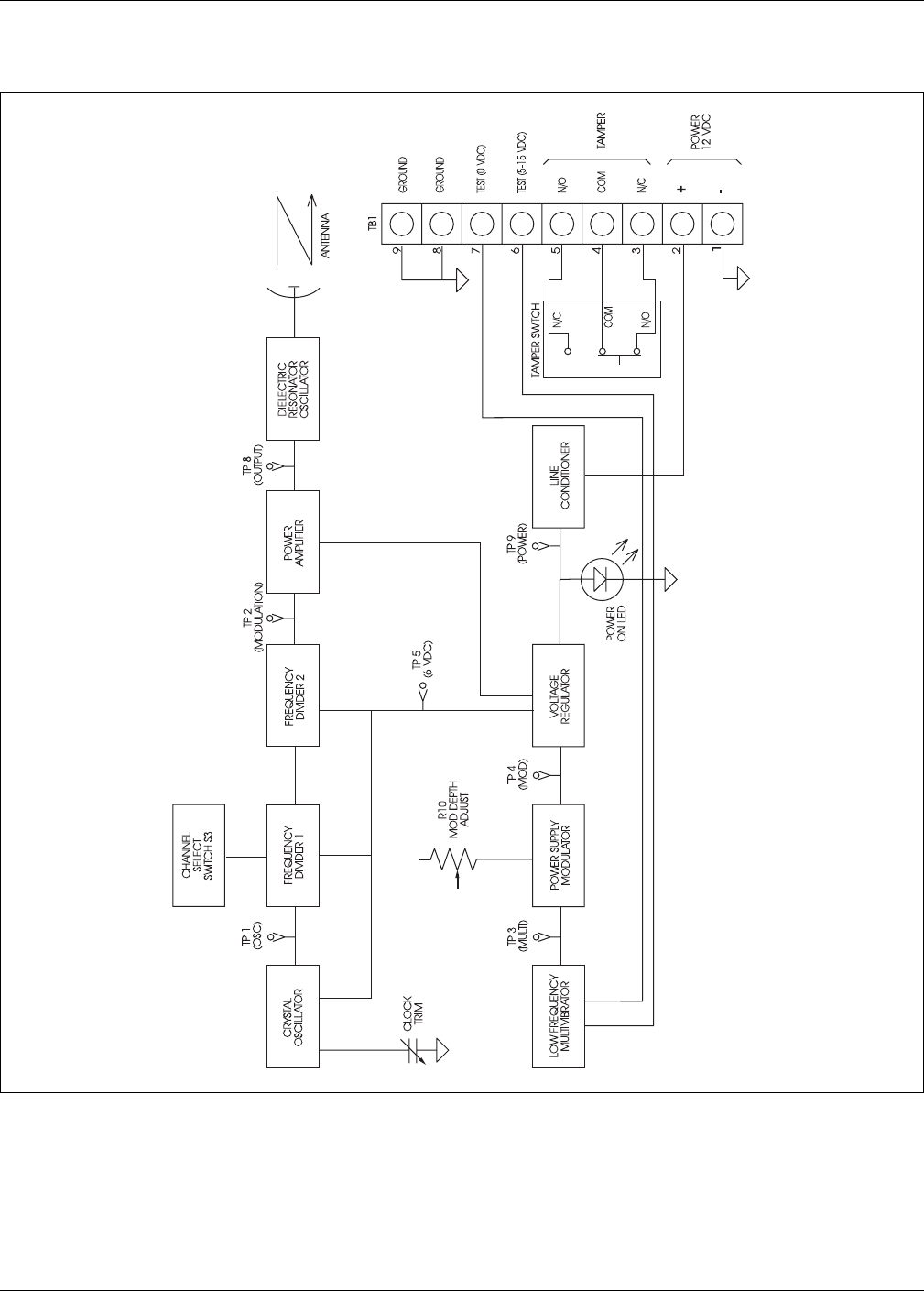
Figure 5-4 is a functional block diagram of the Series 24000 transmitter unit.
Figure 5-4: Transmitter block diagram

CUbYUc"$ Y^cdQ\\QdY_^_`UbQdY_^WeYTUQ!
aSpecifications
General
Voltage requirements •
11 - 15 VDC
Current requirements •
150 mA total per system (maximum)
Operating range •
3 to 150 m (10 to 492 ft.)
Dimensions
•
width - 16 cm (6.25 in.)
•
depth - 9 cm (3.375 in.)
•
height - 31 cm (12.25 in.)
Weight
•
0.9 kg (2 lbs.)
Model 24001 •
standard unit for commercial applications
Model 24004
•
High reliability unit for high security applications - Fully
documented and traceable acceptance test program. Fully tested
(burned in) at high and low temperature extremes.
Transmitter
Operating voltage & current •
11 - 15 VDC, 120 mA maximum
Microwave carrier frequency •
24.125 GHz
± 50 MHz (K-band)
Microwave output •
less than 2.5 volts per meter, maximum at 30 m (98 ft.)
Operating range •
ingress/egress: 150 m (492 ft.)
Separation distance •
transmitter/receiver - high security 100 m (328 ft.)
•
transmitter/receiver - low security 150 m (492 ft.)
Antenna pattern (adjustable)
•
short range - 16º
•
medium range - 11º
•
long range - 7º
Antenna polarization •
E-plane, vertical (E-plane horizontal - optional)
Modulation
•
type: square wave, type A2
•
channels: 6 field-selectable sub-carriers
Tamper circuit contact rating •
1 A, 28 VDC
Operating temperature •
-40º to +66ºC (-40º to +150º F) - Model 24001

Q"CUbYUc"$ Y^cdQ\\QdY_^_`UbQdY_^WeYTU
Receiver
Operating voltage & current •
11 - 15 VDC, 30 mA maximum
Microwave receiver
frequency •
24.125 GHz
Antenna pattern (adjustable)
•
short range - 16º
•
medium range - 11º
•
long range - 7º
Antenna polarization •
E-plane, vertical (E-plane horizontal - optional)
Demodulation •
type A2 - 6 field-selectable sub-carriers
Alarm relay contact rating •
2 A @ 28 VDC
Alarm delay •
adjustable 0.5 sec. to 10 sec.
Tamper circuit contact rating •
1 A, 28 VDC
Audio output •
balanced 600 ohms, output proportional to size and velocity of radar
target, 2 mW max.
Operating temperature •
-40º to +66ºC (-40º to +150º F) - Model 24001

CUbYUc"$ Y^cdQ\\QdY_^_`UbQdY_^WeYTUR!
b
Application notes
The following application notes provide additional information about the Series 24000 bi-static microwave
intrusion detection system:
• Application note # 1 - Do’s and Don’ts: a planning primer
• Application note # 2 - Stacking bistatic microwaves
Introduction
The purpose of this Application Note is to outline the
“rules” for bistatic microwaves, to allow for the successful
installation and operation of microwave units.
Bistatic microwave sensors have been used in security
applications for many years. They operate successfully, as
long as the “rules” for bistatic microwaves are
understood and followed by the planner/consultant, the
installer and the end-user. These “rules” include
limitations in site coverage and detection capability, as
well as the critical need for proper site preparation.
Improper site preparation will result in nuisance alarms
and inconsistent detection.
Microwave basics
A transmitter sends out an electromagnetic wave in the
microwave band toward a receiver. The receiver picks up
an electromagnetic signal composed of both the direct
signal from the transmitter and the reflected signal from
the ground and other nearby objects. Any metallic or
water-containing (living) conductive object moving
within the microwave field alters the received signal in
amplitude and phase. The changes in the received signal
are analyzed, and if they meet the criteria for object size
and speed, an intrusion alarm is declared.
Microwave detection zone size
The size of the microwave detection zone varies greatly
between the transmitter and the receiver. The detection
coverage is very small near either unit, typically 15 cm
(6 in.) in diameter. Therefore, the areas directly below
the transmitter and receiver are unprotected, as
indicated in Figure 1. Microwave units MUST be offset to
provide complete coverage of these unprotected areas,
a s i n d i c a t e d i n F i g u r e s 2 , 3 a n d 4 .
Figure 1: Microwave detection zone
Figure 2: Offset microwave coverage for dead zone
Figure 3: Corner overlap
Beam centerline
small detection
area
large detection
area small detection
area
76 cm (30 in.)
to antenna center
4.5 m
(15 ft.)
offset microwave unit
provides coverage of the area
below the transmitter/receiver
corner overlap
4.5 m
(15 ft.)
4.5 m
(15 ft.)
Intelli-WAVE
& Series 14000, 16000 and 24000 Microwaves
Application Note #1
June 24, 2002
E6DA0109-001, Rev A
DO’s and DON’Ts: a planning primer
page 2 E6DA0109-001, Rev A
Figure 4: Top View- Intermediate Overlap
The detection coverage is largest midway between the
transmitter and receiver. The size of the detection
coverage increases as unit separation increases, as
indicated in Figure 5.
Figure 5: Approximate Intelli-WAVE coverage patterns
The coverage patterns in Figure 5 are for human-size
objects. Large metallic objects, like vehicles or moving
fence panels, can be detected beyond the indicated
envelopes. The pattern is approximately the same
horizontally and vertically, creating an elongated
cylindrical detection field that is tapered at both ends.
However, the pattern does not extend below the surface
of the ground.
Detection capability depends on the sensitivity setting,
the transmitter/receiver separation and mounting height,
and the intruder profile (walking, creeping, crawling, or
rolling). For reliable detection of all intrusion profiles,
the separation between the transmitter and receiver must
not exceed 100 m (328 ft.). This is referred to as a high-
security microwave detection zone.
At the maximum separation distance for bistatic
microwave units, only upright walking intruders are
reliably detected.
Microwave detection is NOT terrain-following. Only line-
of-sight detection is provided by bistatic microwaves.
Unit separation and the mid-point zone width
There is direct relationship between the separation
distance of the transmitter and receiver (zone length),
and the diameter of the detection envelope at the mid-
point of the zone. The approximate beam width
relationship for various products is indicated in Table 1.
The beam width also depends on the sensitivity setting of
the receiver. The beam width increases as the sensitivity
is increased.
Physical limitations to the maximum beam width
The beam width formula can be used to calculate the
maximum transmitter/receiver separation when there is a
physical limitation to the beam width, (for example,
when the microwave units are located between two
parallel fences, or close to buildings). In this case, the
maximum width allowed is divided by the numeric factor
to calculate the zone length. For example, if an
Intelli-WAVE is being installed between two parallel
fences that are 5 m apart, the maximum zone length is
equal to 5 m divided by .0066, which equals 76 m.
However, because large metallic objects can be detected
outside of the envelope, you may have to adjust the
sensitivity or reduce the unit separation accordingly.
If the object that must be excluded from the detection
envelope is to one side only, then the distance from the
beam centerline to the object is determined, and then
doubled to provide the maximum allowable beam width.
The maximum allowable beam width is then used to
calculate the transmitter/receiver separation distance.
top view
beam centerline
beam centerline
intermediate overlap
9 m
(30 ft.)
offset - 46 to 51 cm
(18 to 20 in.)
6 m (20 ft.)
@ 91 m (300 ft.)
12 m (40 ft.)
@ 183 m (600 ft.)
2 m (6 ft. 6 in.)
@ 30 m (100 ft.)
Table 1: Approximate beam width relationships
Product
Beam width relationship
Intelli-WAVE (Model MPS4100)
BW = ZL x 0.066
Microwave Series 14000
BW = ZL x 0.018
Microwave Series 16000
BW = ZL x 0.055
Microwave Series 24000
BW = ZL x 0.035
BW = beam width
ZL = zone length (i.e., unit separation)
E6DA0109-001, Rev A page 3
Site Rules - DO’s and DON’Ts
•DO use bistatic microwave sensors in clear, flat areas
that provide a clean line-of-sight. Bistatic microwave
units are line-of-sight sensors that require a
reasonably long and flat detection zone.
•DON’T use bistatic microwave sensors in areas
where the line-of-sight will be blocked, for example,
in parking areas, where fixed objects are inside the
beam pattern (out buildings, guard shacks), where
power or light poles are in the direct center of beam.
•DO use bistatic microwave sensors in areas where
the ground is smooth and flat.
•DON’T use bistatic microwave sensors over drainage
ditches, hills, or ungraded areas where there is more
than a 15 cm (6 in.) change in terrain over the full
length of the zone. Microwave detection is not
terrain-following (see Figure 6).
Figure 6: DO’s and DON’Ts of installation terrain
•DO use bistatic microwave sensors in areas that are
free of extraneous motion.
•DON’T use bistatic microwave sensors in areas with
trees, shrubs or vegetation in, or near, the detection
zone. Vegetation within the detection zone will cause
nuisance alarms.
•DO eliminate all puddles and areas of standing water
inside the detection zone.
•DON’T use bistatic microwave sensors near large
areas of water, such as ponds, streams, drainage
ditches and water runoff areas.
•DO use bistatic microwave sensors in areas that are
fenced-in (see Figure 7).
•DON’T use bistatic microwave sensors in unfenced/
uncontrolled areas because of potential problems
with animal-initiated nuisance alarms.
•Do limit the length of the microwave zone to exclude
fences, buildings and other reflective surfaces from
inside the detection area. Use additional microwave
units to provide complete coverage of the area.
•Don’t allow fences, buildings or other reflective
objects into the microwave zone or nuisance alarms
and inconsistent detection will result.
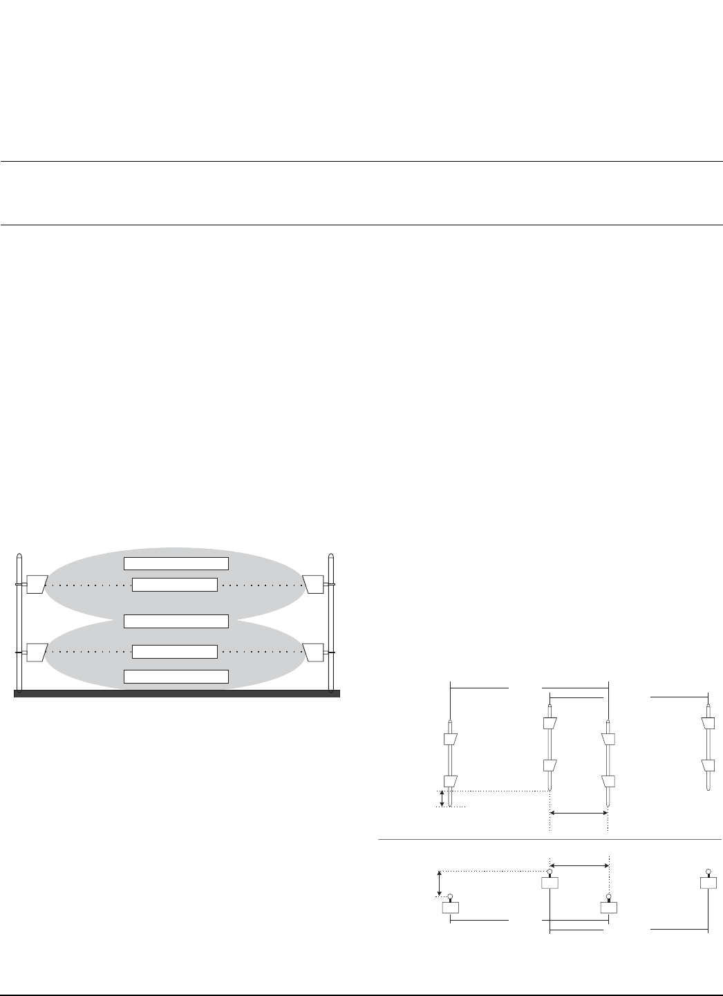
•DO mount microwave units at least 3 m (10 ft.) in
from the fence line for short zones. For longer zones,
follow the guidelines for unit separation.
•DON’T mount the microwave unit too close to the
fence to protect against bridging attempts, and to
avoid nuisance alarms caused by fence movement.
Figure 7: DO’s and DON’Ts for fenced-in areas
•DO keep microwave units away from traffic areas,
and DO provide protective devices to prevent
damage.
•DON’T mount microwave units near fence gates that
can swing into the heads.
•DO use microwave offsets and corner overlaps to
provide complete coverage of an area, including the
transmitter and receiver mounting locations.
•DON’T leave vulnerable areas at the transmitter and
receiver mounting locations.
Ground cover rules for reliable detection
•The transmitter/receiver separation distance must
not exceed 100 m (328 ft.) for high-security
applications.
•The transmitter and receiver units are to be mounted
with the beam centerline (center of antenna) 60 to
75 cm (24 to 30 in.) above the ground (according to
the unit’s installation instructions).
•Terrain within the detection zone must be level to
grade, plus or minus 7.5 cm (3 in.).
•Terrain within the detection zone must be
completely covered with crushed rock (2 cm
(0.75 in.) maximum) to a depth of 10 cm (4 in.).
Crushed rock allows for the proper drainage of
rainwater and prevents the formation of puddles.
•For areas where snow accumulates, pavement is the
recommended surface, to allow for easy snow
removal. Snow build-up can cause changes in the
microwave pattern, which can result in nuisance
alarms. Remove snow, as it accumulates.
DO DON'T

page 4 E6DA0109-001, Rev A
Senstar-Stellar and the Senstar-Stellar logo are trademarks of Senstar-Stellar Corp. Copyright © 2002. All rights reserved.
The information in this application note is subject to change without notice. Printed in Canada.
Senstar-Stellar Corporation
119 John Cavanaugh Drive
Carp, Ontario
Canada K0A 1L0
Telephone: +1 (613) 839-5572
Fax: +1 (613) 839-5830
Website: www.senstarstellar.com
Senstar-Stellar, Inc.
43184 Osgood Road
Fremont, CA
USA 94539
Telephone: +1 (510) 440-1000
1-800-676-3300
Fax: +1 (510) 440-8686
email: info@senstarstellar.com
Senstar-Stellar Limited
Orchard House
Evesham Road
Broadway, Worcs.
U.K. WR12 7HU
Telephone: +44 (1386) 834433
Fax: +44 (1386) 834477
Senstar GmbH
Riedheimer Str. 8
88677 Markdorf
Germany
Telephone: +49 (7544) 95910
Fax: +49 (7544) 959129
Senstar-Stellar Latin America
Pradera No. 214
Col. Pradera
Cuernavaca, Morelos
62170, Mexico
Telephone: +52 (777) 313-0288
Fax: +52 (777) 317-0364
•The detection zone must be completely free from
vegetation, for the full width of the microwave
pattern.
•Perform all routine site maintenance, as required.
Low-security applications
For low security applications where only upright walkers
must be detected, the following ground covers are
acceptable: well-mown grass (7.6 cm (3 in) or less),
asphalt, concrete, or hard-packed soil.
Rules for areas with significant snow accumulation
The accumulation of snow in the detection zone
between the transmitter and receiver reduces their
effective mounting height. The reduction in mounting
height changes the ground reflection characteristic,
which greatly affects the received signal level. Therefore,
it is strongly recommended that snow be removed from
inside the microwave zones.
There are additional problems arising from the
accumulation of snow:
•If the snow blocks the line-of-sight from transmitter
to receiver, the zone stops working.
•Snow drifts may produce “radar shadows”, thereby
increasing vulnerability.
•Intruders can burrow into the snow to avoid
detection.
If snow removal is impractical due to site conditions, the
following procedure should be followed when installing
the microwave sensor:
1. Select the unit’s mounting height from the unit
separation/mounting height charts included on
page 4 of Intelli-WAVE Application Note #2,
Stacking bistatic microwave units
, so that the
operating point is approximately half-way between
two nodal lines. At this mounting height the
received signal will be close to the minimum level.
2. Check the alignment.
For Intelli-WAVE, if the received signal is adequate
(LED 6 or greater on the alignment aid, or a
voltage measurement of 2.5 VDC at tp6 and tp12)
the selected mounting height is correct.
OR
If the received signal is below the minimum
acceptable levels, reduce the mounting height in
small increments, until the signal level is adequate.
3. Ensure that the units are in correct line-of-sight
adjustment.
This procedure will provide the greatest possible margin
for snow accumulation. However this will NOT provide
optimum system performance under normal conditions.
Post mounting and grounding
Each transmitter and receiver is mounted on a 7.6 to 10
cm (3 to 4 in.) steel post, depending on the hardware
supplied. Each post is installed in a concrete base that is
at least 61 cm (24 in.) in diameter and 91 cm (36 in.)
deep, OR 15 cm (6 in.) below the frost line, whichever is
greater. The microwave units must be securely fixed, and
must not move when the wind blows, or when the
ground freezes and thaws.
At each transmitter and receiver location, a proper
ground rod must be installed according to local electrical
codes. The ground rod must be connected to the unit
according to the installation instructions.
Further references
•Installation and Operation Guides for Intelli-WAVE,
Series 14000, Series 16000 and Series 24000
•“General Principles of Microwave Motion Detection”
•“Increasing the Utility of Bistatic Microwave
Intrusion Detection Systems”, Greg Baxter, 1990
•Intelli-WAVE Application Note # 2, Stacking bistatic
microwave units
Contact Senstar-Stellar Corporation to obtain copies of
the above listed material.
Introduction
Bistatic microwave sensors have been used in security
applications for many years. Typically, microwave
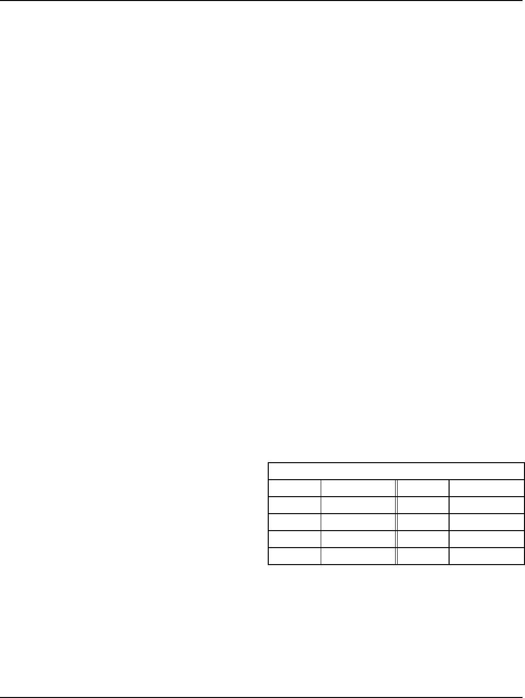
sensors provide a detection zone with a limited height.
One method of increasing the height of the detection
zone is to stack two transmitter-receiver pairs, with one
pair mounted above the other (see figure 1). This
method of stacking microwave sensors can be used to
detect bridging attempts made with ladders or other
climbing apparatus.
This Application Note outlines some of the advantages
and disadvantages of stacking the Intelli-WAVE (Model
MPS 4100), Series 14000, Series 16000, and Series 24000
microwave sensors.
Figure 1: Stacked standalone microwave detection zones
Good practice
Follow the rules for site preparation, ground cover,
clearances and unit separation, as outlined in the
Intelli-WAVE Application Note #1 -
DO’s and DON’Ts: a
planning primer.
The following steps MUST be taken in order to stack two
microwave sensors:
1. Ensure that the two pairs have DIFFERENT
modulation frequencies.
2. Ensure that the two pairs have DIFFERENT
polarizations for the microwave signal. This will
help prevent interference between the two sets of
microwave units.
•
Order one pair with antenna elements rotated 90
degrees, or with Intelli-WAVE, rotate the
antennae prior to installation.
•
The lower pair should have horizontal
polarization (wide beam), and the upper pair
should have vertical polarization (narrow beam).
3. For stand-alone (single zone) or perpendicular
zone configurations, install one transmitter and
one receiver on each post (see Figure 1). Ideally,
the two pairs fire in opposite directions.
Alternatively, the two transmitters or two receivers
can be installed on the same post (see Figure 2).
Generally, the choice is dictated by site wiring
considerations.
4. For multiple in-line zones, mount 2 transmitters
on one post, and 2 receivers on another (see
Figure 2). Ensure that the modulation frequencies
and polarizations of the 2 units on each post are
different.
Figure 2: Stacked multiple in-line microwave detection zones
Beam centerline
Beam centerline
MW Detection zone
MW Detection zone
MW Detection zone
TX
RX
RX
TX
TX
TX
RX
RX
TX
TX
RX
RX
Zone A Zone B
offset width
46 - 51 cm
(18 - 20 in.)
offset length
9.1 m (30 ft.)
side view
top view
TX RX
TXRX
offset width
46 - 51 cm
(18 - 20 in.)
offset length
9.1 m (30 ft.)
Zone A
Zone B
Intelli-WAVE
& Series 14000, 16000 and 24000 Microwaves
Application Note #2
September 27, 2002
E6DA0209-001, Rev B
Stacking bistatic microwave units
page 2 E6DA0209-001, Rev B
5. For multiple zone configurations, carefully plan
the layout, ensuring that there are no possible
conflicts or interference in modulation frequency
or polarization.
6. Use a minimum 10 cm (4 in.) post to ensure
stability. Each post must be installed in a concrete
base that is at least 61 cm (24 in.) in diameter and
either 91 cm (36 in.) deep, OR, 15 cm (6 in.) below
the frost line, whichever is greater.
Determining the mounting height
The received signal is the vector sum of the direct signal
and the reflected signals. The quiescent (no intruder)
received signal is greatly influenced by the mid-point
reflections. The phase relationship between the direct
and reflected signals will slowly change as the sensor
antennas are raised from the ground level.
The two signals (direct and reflected) will combine
constructively (in phase), or destructively (out of phase),
depending on the sensor mounting height and
separation distance. Constructive phasing is preferable
because of the higher net signal level received.
Destructive phasing should be avoided because the low
signal level causes the receiver’s automatic gain control
(AGC) to operate closer to the top of its range. This will
result in a higher nuisance alarm rate when the
microwave path loss increases, for example, during rain
or snow.
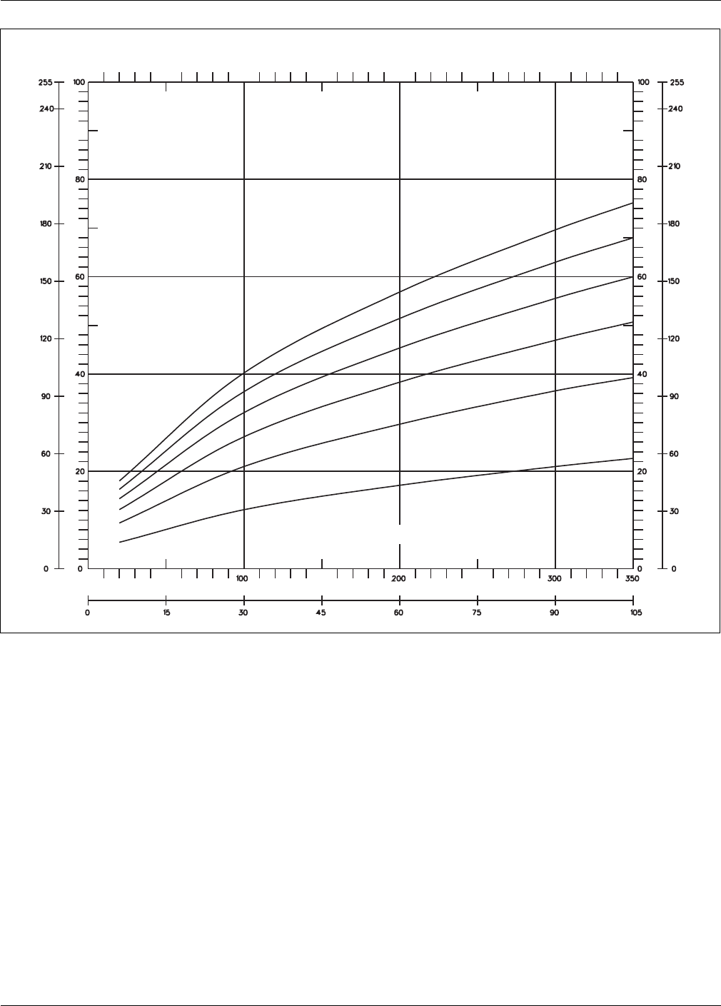
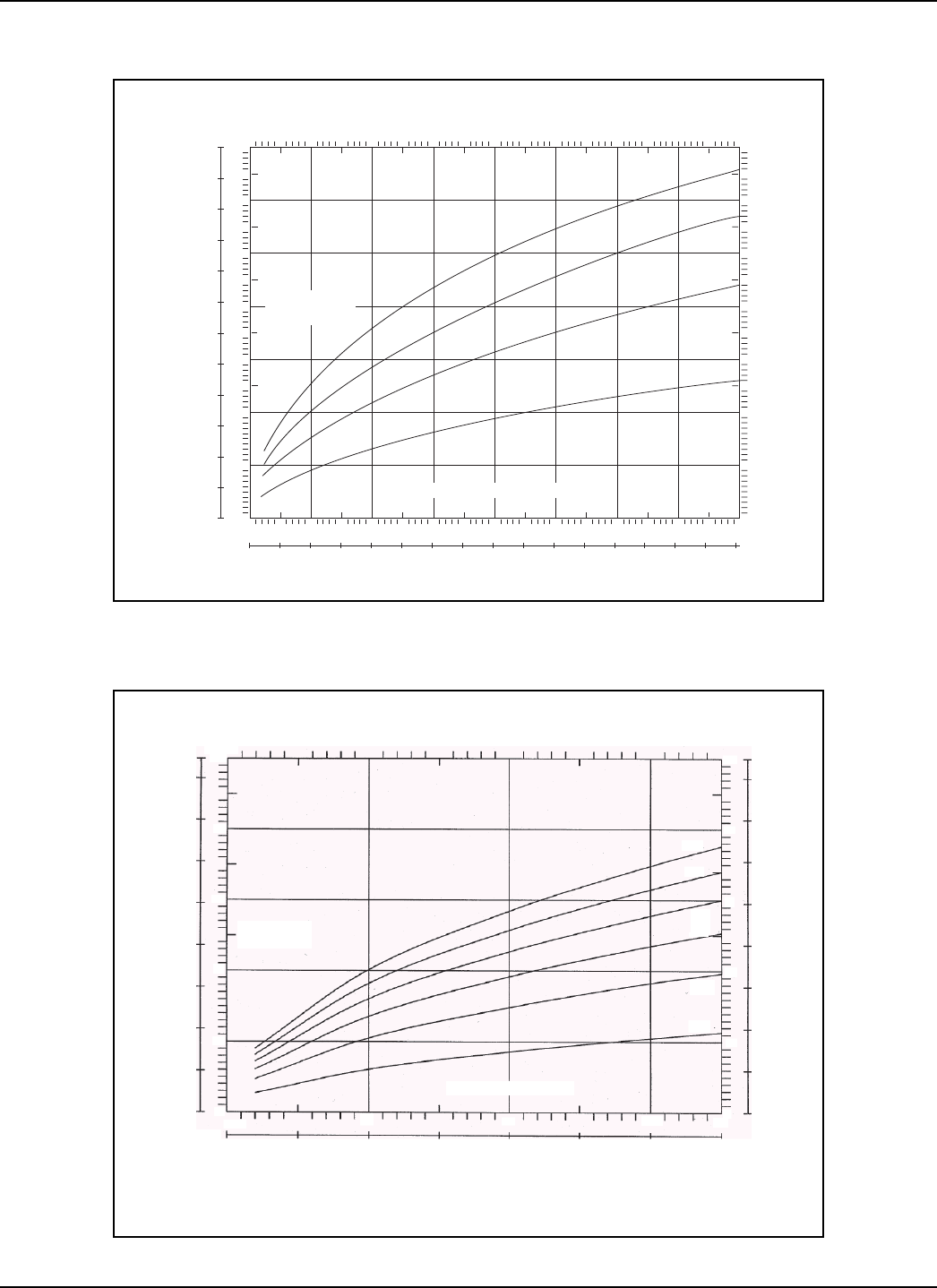
Charts 1 and 2 on page plot the calculated antenna
height versus the separation distance relationship for
constructive phasing for X-Band (Intelli-WAVE,
Microwave Series 14000, and Series 16000) and for
K-Band (Microwave Series 24000) respectively. The
calculation assumes that the two antennas (transmit and
receive) are mounted at the same height above a
relatively flat surface. The areas of constructive phasing
are located on each nodal line, (i.e., N1, N2, N3, etc.) and
below N1.
The following procedure and recommended mounting
height table provide a starting point for determining the
mounting height for your specific application. Many
factors must be taken into account to ensure optimum
performance. Therefore, some adjustments to the
recommended mounting heights will most likely be
required.
Mounting height procedure
1. Determine the unit separation in accordance with
the detection requirements and clearances (see the
Intelli-WAVE Application Note #1 -
DO’s and
DON’Ts: a planning primer
).
2. For the lower pair, select the mounting height of
the center of the antenna from Table 1,
Recommended mounting heights. Adjust the
height to ensure that the operating point is below
N1 (see Chart 1 or 2).
3. For an installation where both X-Band and K-Band
microwave units are being employed, the K-Band
(Microwave Series 24000) unit MUST be the lower
unit.
K-Band microwave sensors have better sensitivity
to slow-moving intruders. However, they are more
susceptible to nuisance alarms from rain and snow.
The closely spaced nodal lines (Chart 2) for K-Band
microwaves means that if the K-Band unit is used
as the upper unit, it will be very difficult to ensure
constructive phasing under all weather conditions.
4. For the upper units, select the mounting height of
the center of the antenna from Table 1,
Recommended mounting heights. Adjust the
height to ensure that the operating point is on a
nodal line, and that the received signal strength is
at the maximum possible.
5. Ensure that both the transmitter and the receiver
of each pair are mounted at the same height.
6. Perform all site maintenance as required.
* Ensure that the operating point (mounting height
versus separation) is on a constructive nodal line, or
below N1 (see Charts 1 and 2 on the next page).
Table 1 Recommended mounting heights*
Lower unit Mounting height
Upper unit
Mounting height
Intelli-WAVE 76 cm (30 in.)
Intelli-WAVE
150 cm (60 in.)
Series 14000 60 cm (24 in.)
Intelli-WAVE
136 cm (54 in.)
Series 16000 60 cm (24 in.)
Series 16000
120 cm (48 in.)
Series 24000 30 cm (12 in.)
Series 16000
90 cm (36 in.)
E6DA0209-001, Rev B page 3
Chart 1: X-band sensor
140
INCHES
CM
120
100
360
330
300
270
80
240
210
180
60
40
150
120
90
60
30
0
20
0
0 153045607590
100 200 300
METERS
FEET
105 120 135 150 165 180
400 500 600 700 800
195 210 225 240
120
100
80
60
40
20
N2
UNIT SEPARATION
N1
N3
N4
140
MOUNTING
HEIGHT
Chart 2: K-band sensor
INCHES
100
CM
255
240
210
180
150
120
90
60
30
00
20
40
60
80
N6
N5
N4
N3
N2
N1
MOUNTING
HEIGHT
UNIT SEPARATION
FEET
METERS
100 200 300 350
015
30 45 60 75 90 105

page 4 E6DA0209-001, Rev B
Senstar-Stellar and the Senstar-Stellar logo are trademarks of Senstar-Stellar Corp. Copyright © 2002. All rights reserved.
The information in this application note is subject to change without notice. Printed in Canada.
Senstar-Stellar Corporation
119 John Cavanaugh Drive
Carp, Ontario
Canada K0A 1L0
Telephone: +1 (613) 839-5572
Fax: +1 (613) 839-5830
Website: www.senstarstellar.com
Senstar-Stellar, Inc.
43184 Osgood Road
Fremont, CA
USA 94539
Telephone: +1 (510) 440-1000
1-800-676-3300
Fax: +1 (510) 440-8686
email: info@senstarstellar.com
Senstar-Stellar Limited
Orchard House
Evesham Road
Broadway, Worcs.
U.K. WR12 7HU
Telephone: +44 (1386) 834433
Fax: +44 (01386) 834477
Senstar GmbH
Riedheimer Str. 8
88677 Markdorf
Germany
Telephone: +49 (7544) 95910
Fax: +49 (7544) 959129
Senstar-Stellar Latin America
Pradera No. 214
Col. Pradera
Cuernavaca, Morelos
62170, Mexico
Telephone: +52 (777) 313-0288
Fax: +52 (777) 317-0364
Heavy snow areas
Snow accumulation decreases the effective mounting
height. This moves the operating point toward
destructive phasing, which could result in degraded
performance. To compensate for snow accumulation, the
setup of the upper unit should be changed as follows:
•Select the height of the upper pair to be at a point of
destructive phasing midway between two nodal
lines. (As snow accumulates, the effective mounting
height will decrease and the operating point will shift
toward an area of constructive phasing).
•Check the signal strength of the upper unit
according to the product manual. If the signal
strength meets the specification for proper
operation, do NOT adjust the mounting height. If the
signal strength is below the specification, reduce the
mounting height in small increments, until the signal
strength meets the minimum specification.
•Ensure that both units of each pair are in a correct
line-of-sight adjustment.
Advantages of microwave stacking
•increased zone height
•increased Probability of Detection (PD)
(There is double coverage from the two pairs for
most of the zone.)
•With an X-Band, K-Band combination, the lower
K-Band unit is more sensitive to slow-moving, and
crawling intruders.
The upper X-Band unit is more sensitive to faster,
upright intruders. This combination provides
increased detection against both types of intruders
Disadvantages of microwave stacking
•The cost is almost doubled
•The probability of nuisance alarms is increased
•If the lower unit is a K-Band microwave, there may be
an increase of nuisance alarms from rain and snow
•There is a greater potential for interference between
microwave pairs
•Because the upper unit is so high above the ground,
its operating characteristics (received signal) can
change from constructive phasing (strong received
signal) to destructive phasing (weak or no received
signal) with a slight change in mounting height
(Although the mounting height is optimized during
installation, snow accumulation changes the effective
mounting height. Therefore, during a snowstorm as
the snow accumulates on the ground, the operation
of the upper microwave pair can become unreliable.
Some measures can be taken during installation to
anticipate this effect. However, sufficient snow
accumulation will severely affect performance.)
Conclusion
For most installations, the mounting height and
detection coverage of Intelli-WAVE will provide sufficient
protection against bridging attempts, as long as the
recommendations for zone coverage overlap are
followed correctly.
When the stacking of bistatic microwave sensors is
required, Senstar-Stellar recommends the use of two
Intelli-WAVE (MPS 4100) X-Band units:
•Intelli-WAVE is easily field-configured
•Intelli-WAVE antenna elements are field-rotatable
•Intelli-WAVE will have fewer nuisance alarms from
weather effects than an X-Band, K-Band combination