Senstar E4EM0201 ultraWave bistatic receiver User Manual E4DA0402

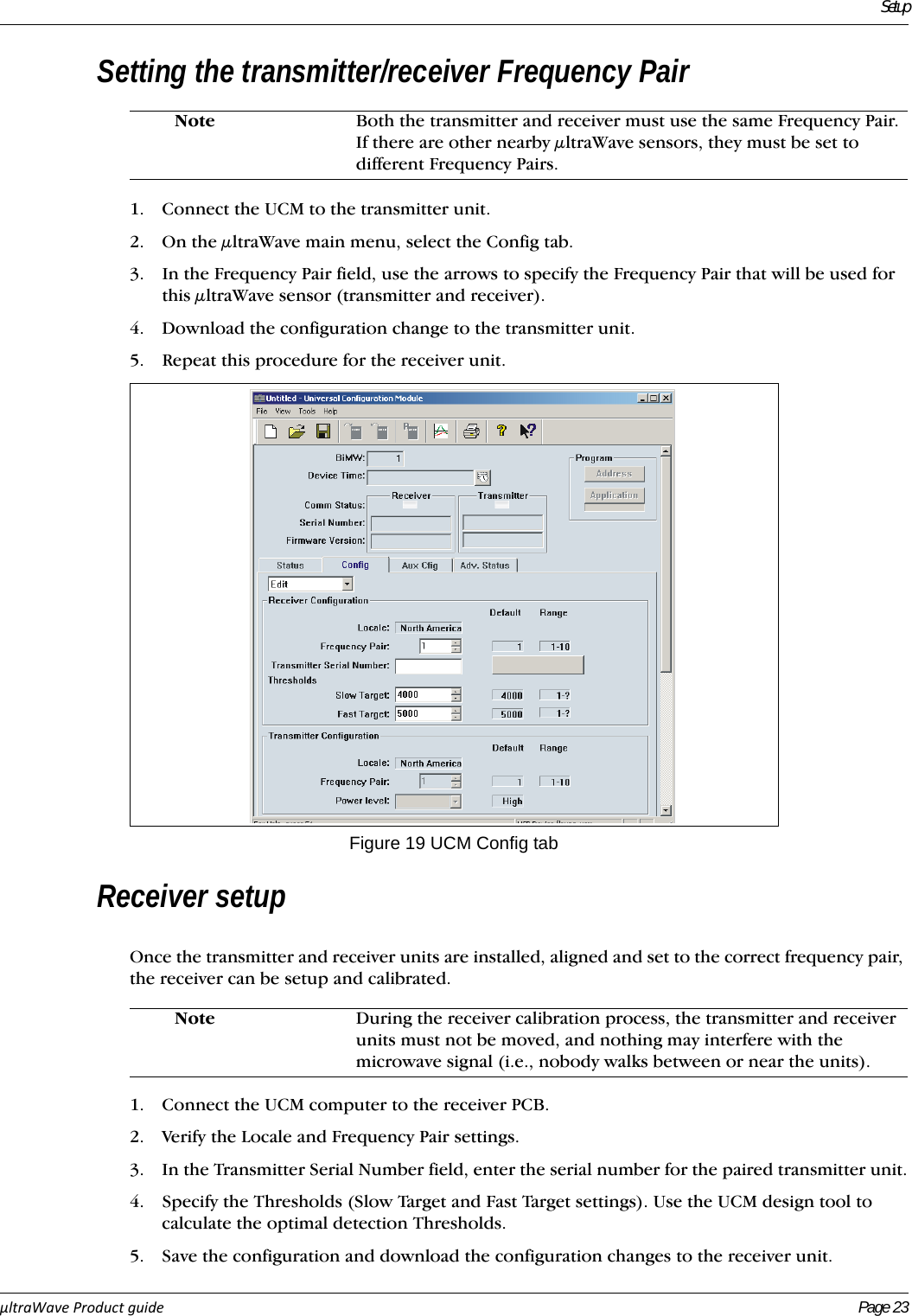
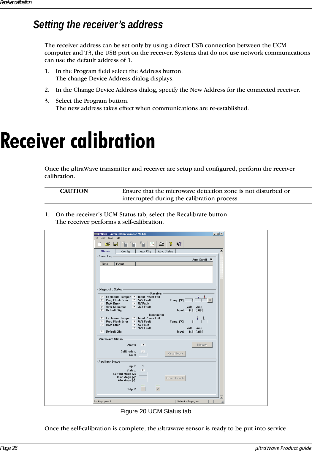
Senstar Corporation ultraWave bistatic receiver E4DA0402

Users manual

ProductGuideµltraWave™Microwave Detection SensorE4DA0402-001 Rev AMarch 25, 2011
µltraWave Product GuideSenstar CorporationWebsite: www.senstar.comEmail address: info@senstar.comE4DA0402-001 Rev AMarch 25, 2011Senstar and the Senstar logo are registered trademarks, and µltraWave and Silver Network are trademarks of Senstar Corporation. Product names and Company names included in this document are used only for identification purposes and are the property of, and may be trademarks of, their respective owners. Copyright © 2011, Senstar Corporation. All rights reserved. Printed in Canada.The information provided in this guide has been prepared by Senstar Corporation to the best of its ability. Senstar Corporation is not responsible for any damage or accidents that may occur due to errors or omissions in this guide. Senstar Corporation is not liable for any damages, or incidental consequences, arising from the use of, or the inability to use, the software and equipment described in this guide. Senstar Corporation is not responsible for any damage or accidents that may occur due to information about items of equipment or components manufactured by other companies. Features and specifications are subject to change without notice. Any changes or modifications to the software or equipment that are not expressly approved by Senstar Corporation void the manufacturer’s warranty, and could void the user’s authority to operate the equipment.The figures included in this document are for illustration purposes only, and may differ from the actual equipment.Senstar Corporation’s Quality Management System is ISO 9001:2008 registered.Compliance:Canada: Industry Canada Identification Number: transmitter 1454B-E4EM0101; receiver 1454B-E4EM0201This device complies with Industry Canada license-exempt RSS standard(s). Operation is subject to the following two conditions: (1) This device may not cause harmful interference, and (2) this device must accept any interference received, including interference that may cause undesired operation.Ce dispositif est conforme aux normes CNR d’Industrie Canada applicables aux appareils radio exempts de licence. Son fonctionnement est sujet aux deux conditions suivantes : 1) le dispositif ne doit pas produire de brouillage préjudiciable; et 2) il doit accepter tout brouillage reçu, y compris un brouillage susceptible de provoquer un fonctionnement indésirable. USA: FCC Identification Number: transmitter 15T-E4EM0101; receiver 15T-E4EM0201FCC Certification - This device complies with part 15 of the FCC Rules. Operation is subject to the following two conditions: (1) This device may not cause harmful interference, and (2) this device must accept any interference received, including interference that may cause undesired operation.This equipment has been tested and found to comply with the limits for a Class B digital device, pursuant to Part 15 of the FCC Rules. These limits are designed to provide reasonable protection against harmful interference in a residential installation. This equipment generates, uses and can radiate radio frequency energy and, if not installed and used in accordance with the instructions, may cause harmful interference to radio communications. However, there is no guarantee that interference will not occur in a particular installation. If this equipment does cause harmful interference to radio or television reception, which can be determined by turning the equipment off and on, the user is encouraged to try to correct the interference by one or more of the following measures:• Reorient or relocate the receiving antenna.• Increase the separation between the equipment and receiver.• Connect the equipment into an outlet on a circuit different from that to which the receiver is connected.• Consult the dealer or an experienced radio/TV technician for help.Europe: This device complies with ETSI standard EN 300 440 for European operationThe use of shielded cables is required for compliance. Service statement - We ensure that our products are correctly applied to achieve the maximum benefits for the end-user. We work hand-in-hand with our customers and remain accessible through all stages of a project - from concept to deployment to long-term support. We provide design assistance, site surveys, installation support, comprehensive documentation, training, post-installation annual calibration and maintenance visits, electronics and software extended warranty, rapid factory repair service and on-call/emergency service. Contact Senstar Corporation to inquire about how a package can be customized for your unique applications.
µltraWaveProductGuide Page1Table of contents1 System planning   - - - - - - - - - - - - - - - - - - - - - - - - - - - - - - - - - - - - - - - 3Site planning   - - - - - - - - - - - - - - - - - - - - - - - - - - - - - - - - - - - - - -  4Site design - - - - - - - - - - - - - - - - - - - - - - - - - - - - - - - - - - - - - - - - - - -  4Zone placement - - - - - - - - - - - - - - - - - - - - - - - - - - - - - - - - - - - - - - - - 5Zone length   - - - - - - - - - - - - - - - - - - - - - - - - - - - - - - - - - - - - - - - - - - 5Zone height   - - - - - - - - - - - - - - - - - - - - - - - - - - - - - - - - - - - - - - - - - - 5Microwave offsets - - - - - - - - - - - - - - - - - - - - - - - - - - - - - - - - - - - - - - - 6Mounting heights  - - - - - - - - - - - - - - - - - - - - - - - - - - - - - - - - - - - - - - - 7Power and ground requirements  - - - - - - - - - - - - - - - - - - - - - - - - - - - - - 8Alarm data communications - - - - - - - - - - - - - - - - - - - - - - - - - - - - - - - - 8Network wiring   - - - - - - - - - - - - - - - - - - - - - - - - - - - - - - - - - - - - - - - - 8Relay contact ratings - - - - - - - - - - - - - - - - - - - - - - - - - - - - - - - - - - - - - 9Cable ports - - - - - - - - - - - - - - - - - - - - - - - - - - - - - - - - - - - - - - - - - - - 9Mounting posts/surfaces   - - - - - - - - - - - - - - - - - - - - - - - - - - - - - - - - - - 9Foundation  - - - - - - - - - - - - - - - - - - - - - - - - - - - - - - - - - - - - - - - - - - 102 Installation - - - - - - - - - - - - - - - - - - - - - - - - - - - - - - - - - - - - - - - - - -  11Mounting the μltraWave units - - - - - - - - - - - - - - - - - - - - - - - - - - -  12Post-mounting procedure - - - - - - - - - - - - - - - - - - - - - - - - - - - - - - - - -  12Post-mount alignment  - - - - - - - - - - - - - - - - - - - - - - - - - - - - - - - - - - -  13Surface-mounting   - - - - - - - - - - - - - - - - - - - - - - - - - - - - - - - - - - - - - 14Surface mounting procedure   - - - - - - - - - - - - - - - - - - - - - - - - - - - - - - 14Surface-mount alignment - - - - - - - - - - - - - - - - - - - - - - - - - - - - - - - - - 15Transmitter/receiver wiring connections  - - - - - - - - - - - - - - - - - - - - - - -15Relay contact ratings - - - - - - - - - - - - - - - - - - - - - - - - - - - - - - - - - - - - 16Auxiliary input  - - - - - - - - - - - - - - - - - - - - - - - - - - - - - - - - - - - - - - - - 16Cable ports - - - - - - - - - - - - - - - - - - - - - - - - - - - - - - - - - - - - - - - - - -  16Making the I/O wiring connections   - - - - - - - - - - - - - - - - - - - - - - - - - - 17Enclosure tamper switch   - - - - - - - - - - - - - - - - - - - - - - - - - - - - - - - - - 17Transmitter/Receiver grounding - - - - - - - - - - - - - - - - - - - - - - - - - - - - -  17Power supply connection - - - - - - - - - - - - - - - - - - - - - - - - - - - - - -  17Local power supply - - - - - - - - - - - - - - - - - - - - - - - - - - - - - - - - - - - - -  17Silver Network wiring connections  - - - - - - - - - - - - - - - - - - - - - - - -  18Silver Network specifications - - - - - - - - - - - - - - - - - - - - - - - - - - - - - - - 18Silver Network connections - - - - - - - - - - - - - - - - - - - - - - - - - - - - - - - -  193 Setup and calibration   - - - - - - - - - - - - - - - - - - - - - - - - - - - - - - - - - - -  21Connecting the UCM  - - - - - - - - - - - - - - - - - - - - - - - - - - - - - - - -  22Setting the transmitter/receiver Frequency Pair  - - - - - - - - - - - - - - - -  23Receiver setup - - - - - - - - - - - - - - - - - - - - - - - - - - - - - - - - - - - - -  23Specify the Auxiliary I/O control mode  - - - - - - - - - - - - - - - - - - - - -  24Auxiliary (Aux) inputs   - - - - - - - - - - - - - - - - - - - - - - - - - - - - - - - -  24
Page2µltraWaveProductGuideInput configuration procedure (Remote control mode)   - - - - - - - - - - - - - - 25Output relays   - - - - - - - - - - - - - - - - - - - - - - - - - - - - - - - - - - - - - 25Output relay setup (Local control mode)  - - - - - - - - - - - - - - - - - - - - - - - 25Output relay setup (Remote control mode) - - - - - - - - - - - - - - - - - - - - - - 25Setting the receiver’s address   - - - - - - - - - - - - - - - - - - - - - - - - - - - 26a  Specifications - - - - - - - - - - - - - - - - - - - - - - - - - - - - - - - - - - - - - - - - - 27
µltraWaveProductGuide Page 31 System planningThe μltraWave Microwave Detection Sensor is designed for exterior perimeter intrusion detection applications. μltraWave consists of a microwave transmitter and receiver, which detect motion in a defined area (see Figure 1). The transmitter sends microwave signals to the receiver, and any motion in the detection zone causes a variation in the received signal strength. The signal variations are detected and processed by the receiver, which declares an intrusion alarm when the received signal meets the criteria for a valid target.The transmitter and receiver units are housed in weatherproof enclosures. Each enclosure contains electronic circuitry and an antenna. Both units can be wired to report enclosure tamper alarms. Site planning & designThe amount of site preparation required depends on the level of security. High security applications require more stringent specifications than do applications where only a beam-break alarm is required. Use the following definitions to determine the level of security required:• High Security Zone - detection of an intruder stomach-crawling parallel to the beam.• Medium Security Zone - detection of an intruder crawling on hands and knees.• Low Security Zone - detection of an upright walking intruder (beam-break alarm). The physical specifications for a high security detection zone are:• maximum transmitter/receiver separation distance of 100 m (328 ft.)• terrain must be level to grade ± 7.5 cm (3 in.)• terrain covered with a 10 cm (4 in.) layer of crushed stone (2 cm {0.75 in.} max.) or a paved zone free of vegetationFigure 1 µltraWave microwave detection sensorpartial coveragemounting heightfull coveragedetection zone partial coveragebeam centerlineoffset area offset area
Site planning & designPage 4 µltraWaveProductGuideSite planningConduct a site survey in which you note the physical features of the zone and surrounding area. Include accurate measurements on a detailed drawing. The following is a list of rules to follow when planning a microwave zone:• Line of sight - A direct, unobstructed line of sight is required between the transmitter and receiver.• Depressions and deviations in terrain - Drainage ditches and gullies must be avoided or filled in. These depressions can allow undetected access by an intruder, and occasional water flow can cause nuisance alarms. Significant deviations from level grade can result in gaps in the detection zone and detection shadows. Gaps and detection shadows create unmonitored areas in the zone.• Vegetation - Trees, bushes, shrubs, tall grass and weeds within the detection zone will increase the sensor’s nuisance alarm rate and reduce the probability of detection, especially when the vegetation is wet with rain or dew.• Objects - Any objects (posts, light standards, stored material, parked vehicles, etc.) within the detection zone can result in gaps in the microwave field and detection shadows.• Ensure that there is adequate separation from any object that could be used to jump over or bridge the detection zone (e.g., fences, trees, storage sheds, etc.).• Motion - Movement within the detection zone can cause nuisance alarms (trees, brush, shrubs, weeds, etc.).The detection zone must not include water, which can cause nuisance alarms when moving (e.g., puddles, ponds, streams, lakes). The detection zone must be fenced in to prevent nuisance alarms caused by animals (cats, dogs, rabbits, deer, livestock, etc.). The motion of metallic objects (vehicles, buildings, fences, materials, etc.) that are close to the detection zone can produce nuisance alarms.• Ground surface - The type of ground surface in the detection zone affects the sensor’s operation:Crushed stone is the optimum ground cover. Crushed stone disperses rain and helps to prevent the formation of puddles. In addition, microwave energy reflects off the rocks, thereby increasing the zone’s sensitivity.Paved surface - A paved surface is recommended for detection zones that require snow removal. Accumulated snow changes the characteristics of the detection zone and can provide cover for a burrowing intruder.Other acceptable surfaces for medium and low security applications include closely mowed grass (7.5 cm {3 in.} or less) and hard-packed dirt or clay.Site designPrepare detailed site drawings for the μltraWave system after completing the site survey. Include dimensions, elevations and the locations of any objects noted during the survey. Once the site drawings are complete, carefully plot each microwave zone. Zone placement, zone length, and offsets are critical factors in the design of a microwave sensor system.Note The Universal Configuration Module includes a tool that calculates microwave offsets, mounting heights, beam width, and clearance requirements, based on zone lengths. Use the UCM design tool when planning an μltrawave zone.
Site planning & designµltraWaveProductGuide Page 5Zone placementThe μltrawave system requires a long, flat, detection zone free of obstacles and depressions. The minimum distance between the beam centerline and any object (fences, buildings, vehicles, trees, bushes, shrubs, etc.) is outlined in Tabl e 1 . Separation distances are based on typical conditions and can vary depending on site conditions including zone length, unit mounting height, ground cover, type of obstacle, etc. The following separation distances are minimum values. Increase the separation distance between the beam centerline and any objects whenever possible.You can calculate the required minimum clearance between the beam centerline and an object by using the following formula:(transmitter/receiver separation) X 0.02 = (min. distance between beam centerline and object)The formula can also be used to calculate the maximum separation between the transmitter and receiver when you know the available clearance between the beam centerline and the nearest object:(transmitter/receiver separation) = (min. distance between beam centerline and object) / 0.02Zone lengthThe optimum length of each zone depends on several factors:• the required level of security • physical constraints (terrain, trees, fences, buildings, etc.)• available space for the detection zoneFor a high security zone, the maximum zone length is 90 m (295 ft.) and the maximum distance between the transmitter and receiver is 100 m (328 ft.).For a medium security zone, the maximum zone length is 140 m (459 ft.) and the maximum distance between the transmitter and receiver is 150 m (492 ft.).For a low security zone, the maximum zone length is 200 m (656 ft.) and the maximum distance between the transmitter and receiver is 200 m.Zone heightThe height of the microwave field is approximately equal to the minimum distance between the beam centerline and an object (see Table 1 ) plus the unit mounting height. For applications that require additional zone height it is possible to stack two or more units on one mounting post. Stacking μltrawave sensors is described in application note E4DA0109.transmitter/receiver separation min. required clearance (beam centerline to object) midpoint zone width30 m (98 ft.) 0.6 m (2 ft.) 1.2 m (4 ft.)50 m (164 ft.) 1.0 m (3.3 ft.) 2.0 m (6.6 ft.)75 m (246 ft.) 1.5 m (5 ft.) 3 m (10 ft.)90 m (295 ft.) 1.8 m (6 ft.) 3.6 m (12 ft.)100 m (328 ft.) 2.0 m (6.6 ft.) 4.0 m (13.2 ft.)125 m (410 ft.) 2.5 m (8.2 ft.) 5.0 m (16.4 ft.)150 m (492 ft.) 3.0 m (10 ft.) 6.0 m (19.7 ft.)200 m (656 ft.) 4.0 m (13.2 ft.) 8.0 m (26.3 ft.)Table 1 Unit separation/minimum clearance
Site planning & designPage 6 µltraWaveProductGuideMicrowave offsetsThe areas immediately above and below the transmitter and receiver antennas are not exposed to the microwave energy. A microwave offset is used to prevent this unmonitored area from being vulnerable to undetected intrusions (see Figure 2). Offsets prevent intruders from crawling under or jumping over a microwave unit to gain undetected access to the protected area. The offset distances in the example drawings are based on a 100 m separation between the transmitter and receiver and a mounting height of 55 cm (21.5 in.) beam centerline to ground. As the mounting height increases a longer offset is necessary. Different types of offsets are shown in Figure 3. Figure 2  Offset areaFigure 3 Offset arrangement examplespartial coveragepartial coveragebeam centerline fullcoveragedetection zonerequired offset5 m(16.4 ft.)55 cm(21.5 in.)5 m(16.4 ft.)detection zoneprotected areabeam centerlinecorner offset55 cm (21.5 in.) mounting heightbasket weave layoutfor odd shaped perimeters1 m (3.3 ft.)10 m (32.8 ft.)parallel offset55 cm (21.5 in.) mounting heightTR5 m(16.4 ft.)TRRRRRRRTTTTTTTTTTTTRRRT
Site planning & designµltraWaveProductGuide Page 7Mounting heightsThe recommended method for determining the μltraWave unit mounting height is to use the UCM design tool. However, the mounting height chart (see Figure 4) can also be used to determine the optimal mounting height for the transmitter and receiver. The horizontal axis of the chart represents the separation distance between the transmitter and receiver. The vertical axis represents the height of the transmitter and receiver from the center of the antenna to the ground’s surface.The node curves (N1, N2, N3, N4, N5 and N6) indicate the recommended locations for coordinating distance (horizontal axis) to mounting height (vertical axis). Coordinate lines that meet on the node curves provide the highest received signal strength. Avoid the mounting height and distance coordinates between the node curves. For high security applications, a mounting height at N1 will provide optimum system operation.Example:The distance between the transmitter and receiver is 85 m (279 ft.). Locate this distance on the height chart's horizontal axis. Plot a vertical line from this distance point across the node curves. These height measurements represent the best theoretical mounting heights for this example. They are 50 cm (20 in.) for the N1 curve, 70 cm (28 in.) for the N2 curve, 87 cm (34 in.) for the N3 curve, etc.Figure 4  Mounting height chart01020304050607080901001101201301401501601701801902000 10 20 30 40 50 60 70 80 90 100 110 120 130 140 150 160 170 180 190 200N1N2N3N4N5N633 66 98 131 164 197 230 263 295 328 361 394 427 459 492 525 558 591 623 656 feetmeterscminches79757167635955514743393532282420161284mounting heighttransmitter/receiver separationN1N2N3N4N5N6Nodecurves
Site planning & designPage 8 µltraWaveProductGuidePower and ground requirementsThe μltraWave sensor system consumes 4 W maximum. Both the transmitter and receiver can operate on a wide range of input voltages (12 to 48 VDC). The required gauge of the power cable depends on the power supply capacity, the number of μltraWave units being powered and the lengths of the power cable runs. In locations where AC power may not be stable or reliable, an uninterruptable power supply (UPS) should be used for primary power. Each μltraWave unit requires a nearby connection to a low resistance earth ground.  Alarm data communicationsAlarm monitoring is site specific and depends on whether you are using relay output alarm communications (Local control mode) or network based alarm communications (Remote control mode). Each unit has two user-configurable Form C relay outputs. In Local control mode, the receiver’s two outputs can be configured to signal alarm, Tx comm link fail, enclosure tamper (transmitter and receiver unit) input power fail, hardware faults (transmitter and receiver unit) and system fail (fail-safe operation). The transmitter unit’s two outputs can be configured to signal enclosure tamper, input power fail, hardware faults and system fail (fail-safe operation). Each receiver unit also includes an auxiliary (Aux) input. The Aux input is not used in Local control mode. To communicate on the Silver Network, a network interface card (NIC) must be installed on the receiver PCB. There are five variants of the NIC available: EIA-422, multimode fiber optic, singlemode fiber optic, mixed media EIA-422 and multimode, and mixed media EIA-422 and singlemode. For network based systems (Remote control mode) alarm data is carried over the network cables and the relays are available as output control points from the security management system. The transmitter’s tamper notification is transmitted to the receiver unit, which notifies the security management system of a tamper condition. In Remote control mode the receiver’s Aux input can be used to report the status of an auxiliary security device to the head end. The transmitters Aux input is not used in Remote control mode. Network wiringTransmission media/maximum separation distances between μltraWave receivers using network communications:• EIA-422 copper wire - 1.2 km (0.75 mi.) • Multimode fiber optic cable - 2.2 km (1.4 mi.) - 2 fibers per Channel• Singlemode fiber optic cable - 10 km (6.2 mi.) - 2 fibers per ChannelNote Senstar recommends installing a low resistance (5Ω or less) earth ground at each unit. Consult the local electrical codes for grounding information.Note It is possible to use relay output alarm communications and setup a Silver Network for maintenance purposes. This enables remote calibration, maintenance and diagnostic access to your μltrawave units from a central control facility.Note A network interface card must be installed on the receiver PCB to enable network communications.Note Senstar strongly recommends the use of low capacitance shielded twisted pair data cable for EIA-422, 62.5/125 multimode fiber optic cable, and 9/125 singlemode fiber optic cable.
Site planning & designµltraWaveProductGuide Page 9Relay contact ratingsThe dry contact relays are single pole, double throw, Form C, latching, rated for 30 V @ 1 A max. In Remote control mode, you can configure the relays as latching (ON by command, OFF by command), in flash mode (ON-OFF-ON-OFF, etc. by command, then OFF by command), or pulse mode (ON for a period, then OFF). For flash and pulse modes, the relay Active/Inactive times are selectable. In Local control mode the relays remain active for the event’s duration or for the selectable Hold Time, whichever is longer.Cable portsEach μltraWave unit includes two 22 mm (0.875 in.) cable ports. The post-mounting kit (E4KT0300) includes two compression glands for cable sizes 5 mm to 6.4 mm (3/16 in. to 1/4 in.) and two alternate compression glands for cable sizes 11 mm to 13 mm (7/16 in. to 1/2 in.). If required, the enclosure can be fitted with 13 mm (1/2 in.) conduit, in place of the compression glands. Mounting posts/surfacesThe μltraWave units mount easily on posts with an outside diameter ranging between 4.8 cm and 11.4 cm (1.875 in. and 4.5 in.). The posts must be plumb, firmly set in the ground, and unable to rotate or move. For areas where the ground freezes, the posts must be protected against potential frost heaving. A 2.5 m (8 ft.) post is generally used with 91 cm (3 ft.) of the post buried in a concrete footing. Figure 5 is an illustration of a post-mounted μltraWave unit.  Note Conduit and conduit fittings are not included.Figure 5 Post installation and unit mounting4.8 to 11.4 cm postpower and alarmwiring in conduitground wireground rodµltraWave unitmounting height fromcenter of antenna to groundground levelburied conduitto alarm panel& power supplyrebarthrough post 61 cm(2 ft.) concrete footing91 cm *(3 ft.)Consult the local construction codes for information about usingconcrete footings in ares where ground freezing occurs.*
Site planning & designPage 10 µltraWaveProductGuideFoundationThe foundation for the mounting posts in normal soil should be at least 91 cm (3 ft.) deep and 61 cm (2 ft.) in diameter. If soil conditions are such that a non-shifting foundation is questionable, then a larger footing is required. In areas where ground freezing can cause frost heaving, use a truncated pyramid base foundation.When the foundation concrete cures, there is a possibility of it pulling away from the post, thereby, allowing the post to rotate. Installing a length of rebar through the post in the concrete foundation will prevent any rotation.Surface-mount applicationsThe post-mount bracket can also be used to mount an μltraWave unit on a fixed stable surface. The hardware required for fastening the bracket to the surface is not included. If you are considering a surface mount application, the transmitter receiver alignment must be carefully planned, as the mounting bracket cannot be adjusted in the horizontal plane for surface mount applications. Note Senstar recommends hiring a local fencing contractor to install the μltraWave mounting posts.Figure 6 Surface mounting examplepower and alarmwiring in conduitground wireground rodµltraWave unitmounting height fromcenter of antenna to groundground levelmountingbracket
µltraWaveProductguide Page 112 Installation The μltraWave transmitter and receiver units are almost identical, with only minor differences in component layout. Figure 7 shows an μltraWave receiver and illustrates the unit’s features. The receiver’s diagnostic activity LEDs are listed in Tab le  2 .Figure 7 µltraWave receiver PCBLED # Description LED # DescriptionD37 POWER LED ON = DC input Power ON D6 RXA LED ON = receiving A-side network commD35 ALARM LED ON = sensor alarm D7 TXA LED ON = transmitting A-side network commD34 DOOR LED ON = enclosure tamper condition D8 RXB LED ON = receiving B-side network commD33 MEMEORY LED ON = internal memory fault D9 TXB LED ON = transmitting B-side network commD36 POWER FAIL LED ON = power rail fault D10 FAULT A LED ON = A-side communication faultD37 RESERVED D11 FAULT B LED ON = B-side communication faultD31 RESERVED D12 NETWORK POWER LED ON = NIC power OND30 UCM ACTIVE LED ON = UCM connected D13 BOOT LED ON = NIC initialization failureD24 ALARM LED ON = sensor alarm (default) D16 POWER LED ON = input power faultD25 SUPERVISION LED ON = supervision alarmTable 2 µltraWave diagnostic activity LEDscenter of antennaUSB port (connect UCM PC)diagnostic activity LEDsNIC mounting hardware (X 3)T1 expansion header (for NIC)power fault LEDT3 power input connectionT6 input/output connectionsrelay active LEDsT4 bypass tamper headerS1 tamper switchPCB earth ground connection22 mm cable entry ports
Page 12 µltraWaveProductguideMounting the µltraWave unitsMount the transmitter and receiver units on their respective posts, using the hardware provided in the post-mounting kit (p/n E4KT0300, see Figure 8 ). The mounting height of the transmitter and receiver units is measured from the center of the antenna to the ground’s surface. As an alignment aid, the cover over the antenna includes an embossed X-pattern, that indicates the center of the antenna.The μltraWave units can also be mounted on a wall or other flat stable surface. Both the transmitter and receiver units must be mounted at the same height above ground. After mounting, the two units must be aligned to point directly at each other. Post-mounting procedure1. Using an 11 mm (7/16 in.) wrench and the supplied hardware (hex nut, lock washer, flat washer - X4) attach the mounting bracket to the μltraWave unit (see Figure 9 ).2. Pass the gear clamp through the slots in the post collar.3. Using an 11 mm wrench and the supplied hardware (bolt, lock washer, flat washer - X4) attach the post collar to the mounting bracket.4. Wrap the gear clamp around the post and measure the mounting height of the μltraWave unit from the center of the antenna (see Figure 8 ) to the ground’s surface. 5. Aim the μltraWave unit at the second mounting post, and using an 8 mm (5/16 in.) nut driver or socket, tighten the gear clamp with the μltraWave unit at the specified height.6. Measure and verify the mounting height.7. Repeat for the second μltraWave unit.Note Senstar recommends hiring a local fencing contractor to install the μltraWave mounting posts.Figure 8 Mounting hardware/alignment aidmounting bracketpost collargear clampE4KT0300 post-mounting kithardwareEach µltraWave unit includes one set ofthe following hardware components: compression glandsand alternatesmounting bracket to µltraWave unit
µltraWaveProductguide Page 13Post-mount alignmentFor optimal performance, ensure that the μltraWave transmitter and receiver are aimed directly toward each other, and that the mounting height is correct for both units (see Figure 10 ). 1. Measure and verify the mounting heights of both units.2. If required, loosen the transmitter’s gear clamp slightly, and then carefully aim the transmitter directly at the receiver.3. Tighten the transmitter’s gear clamp.4. If required, loosen the receiver’s gear clamp slightly, and then carefully aim the receiver directly at the transmitter.5. Tighten the receiver’s gear clamp.6. If required, loosen the four bolts that attach the post collar to the mounting bracket and aim the units (in the vertical axis) toward each other. Re-tighten the bolts.Figure 9 Post-mounting procedure
Page 14 µltraWaveProductguideSurface-mountingThe μltraWave mounting bracket can be used to surface mount the transmitter and/or receiver. The mounting bracket is attached to the μltraWave unit, and then to the post collar. The post collar is rotated 180º so the flat side is facing outward toward the mounting surface. Customer-supplied hardware is used to attach the collar to the mounting surface. Surface mounting procedure1. Using an 11 mm (7/16 in.) wrench and the supplied hardware (hex nut, lock washer, flat washer - X4) attach the mounting bracket to the μltraWave unit.Figure 10 µltraWave alignmentCAUTION For surface mount applications, the two mounting surfaces must face toward each other. Surface mounted μltraWave units cannot be rotated in the horizontal axis. If required, use shims to adjust the horizontal alignment of surface mounted units.horizontal adjustmentvertical adjustment
µltraWaveProductguide Page 152. Using an 11 mm (7/16 in.) wrench and the supplied hardware (bolt, lock washer, flat washer - X4) attach the post collar to the mounting bracket with the flat side of the collar to the outside.3. Hold the μltraWave unit against the mounting surface and measure the mounting height of the unit from the center of the antenna to the ground’s surface (see Figure 8 ). Mark the mounting surface at the centers of the two slots in the post collar. 4. Drill two holes in the mounting surface.5. Remove the post collar from the mounting bracket, and use appropriate fasteners to attach the post collar to the mounting surface.6. Re-attach the mounting bracket and μltraWave unit to the post collar. 7. Measure and verify the mounting height.8. Mount the second μltraWave unit.Surface-mount alignmentTo ensure optimal performance, it is critical that the μltraWave transmitter and receiver are aimed directly toward each other, and that the mounting height is correct for both units. 1. Verify the mounting heights of both units.2. If required, loosen the mounting hardware on the post collars, and install shims so that the μltraWave transmitter and receiver point directly at each other (horizontal adjustment).3. Tighten the mounting hardware.4. If required, loosen the four bolts attaching the post collar to the mounting bracket and aim the units toward each other (in the vertical axis). Re-tighten the bolts.Transmitter/receiver wiring connectionsThe μltraWave wiring connections are made on removable terminal blocks. The screw terminals accept wire sizes from 12 to 24 AWG, with a 6.4 mm (0.25 in.) strip length. Remove the terminal blocks to make the wiring connections. Reinstall the blocks after the connections are complete, and verified. The DC power input is made on T3 and the input/output connections are made on T6. The Aux input is available only through Remote control mode when using network communications. Refer to Figure 12  for an illustration of the μltraWave wiring connections.Figure 11 µltraWave alignmentpost collarmounting bracket
Page 16 µltraWaveProductguideT3 - power inputThe μltraWave units require 12 to 48 VDC to operate. Pin 1 is negative and pin 2 is positive.T6 - inputs/outputsT6 connects to output 1, output 2 and an auxiliary (Aux) input (see Figure 12  for connection details). In Local control mode each output is configured via the UCM to report user-specified alarm conditions (see Alarm data communications on page 8). The Aux input is not used in Local control mode.In Remote control mode the outputs are used by the security management system as output control points. The Receiver’s Aux input is available to report the status of an auxiliary security device. The Aux input on the transmitter is not used. Relay contact ratingsThe dry contact relays are single pole, double throw, Form C, latching, rated for 30 V @ 1 A max. Auxiliary inputIn Remote control mode, the receiver’s AUX input is a voltage sensing input. The receiver determines the input’s status via an internal reference voltage, and the configuration of the contact closures and supervision resistors. Any change in the input’s status is reported to the host security management system. Cable portsEach μltraWave unit includes two 22 mm (0.875 in.) cable ports fitted with compression glands. Remove the compression glands, pull the cables through the glands and into the enclosure. Then replace the compression glands. After making the wiring connections, hand-tighten the compression glands to provide weather protection and strain relief.Figure 12 Transmitter/receiver wiring connectionsNote The contact closure input to the AUX input must be voltage-free.T6T31234567812NCCOMNONCCOMNO-+-+ground connection detailsmachine screwlock washerground wireexternal tooth washerPCB ground connectionPCBpower input(12 to 48 VDC)input/outputconnectionsAUX inputoutput 1output 2(Remote control mode)
µltraWaveProductguide Page 17Making the I/O wiring connections1. Pull the data cable into the enclosure.2. Prepare the data cable - strip length = 6.4 mm (0.25 in.).3. Remove the terminal block from T6, make the wiring connections, and then replace the terminal block (see Figure 12 ).Enclosure tamper switchEach μltraWave unit includes a mechanical tamper switch (closed = secure, open = tamper) to indicate if the enclosure cover is removed. Placing a shunt on header T2 overrides the tamper switch (shunt ON = secure).Transmitter/Receiver grounding1. Connect an approved ground wire to a properly installed ground rod at the μltraWave unit’s installation location.2. Connect the ground wire to the ground lug on the transmitter/receiver PCB (see Figure 12 ).Power supply connectionWhen a central low voltage power supply is being used for primary power, it should be powered from an uninterruptible AC power source.• To power the system from a central source, run the power distribution cable around the perimeter and tap off to each μltraWave unit. Use a minimum 14 gauge wire for power runs up to 1.2 km (4000 ft.). For longer runs use 12 gauge wire.•At each μltraWave unit, splice the power cable to a lighter gauge pigtail that is approximately 30 cm (12 in.) long. Connect the negative lead to T3-1 (-) and connect the positive lead to T3-2 (+) (see Figure 12 ).Local power supplyTo use a local DC power supply outdoors, the power supply must be installed in its own weatherproof enclosure. The local supply can be mounted on the same post as the μltraWave unit to keep the wire runs to a minimum. Connect the negative lead to T3-1 (-) and connect the positive lead to T3-2 (+) (see Figure 12 ).Note Senstar recommends using a low resistance (5Ω or less) earth ground connection at each unit. Consult the local electrical codes for additional grounding information.WARNING! DO NOT bring AC mains power into the μltraWave enclosure. If a local power supply is being used, it must be installed in its own weatherproof enclosure. Consult the local electrical code for information about the connection of AC mains to your power supply.
Page 18 µltraWaveProductguideSilver Network wiring connections Silver Network specifications• Data rate - fixed 57.6 k bps• Maximum 32 devices spread over up to 4 independent network loops• Two communication Channels (Side A, Side B)• Network termination - not required• Transmission media/maximum separation distances between μltraWave receivers:EIA-422 copper wire - 1.2 km (0.75 mi.) Multimode fiber optic cable - 2.2 km (1.4 mi.) - 2 fibers per ChannelSinglemode fiber optic cable - 10 km (6.2 mi.) - 2 fibers per ChannelNote A network interface card must be installed on the μltraWave receiver to enable network communications.Figure 13 Receiver unit Silver Network wiring connectionsNote Senstar strongly recommends the use of low capacitance shielded twisted pair data cable for EIA-422, 62.5/125 multimode fiber optic cable, and 9/125 singlemode fiber optic cable.B-side data path connections *ground connectionT3 power input (see Figure 10) (12 to 48 VDC)T6 input/output (see Figure 10)AUX inputoutput 1output 2A-side data path connections *NIC mounting hardware (X 3)T1 expansion header (solder side)plug into T1 on PCBuse single point groundingconnect one end of the shield, trimback the other end and leave itdisconnected*
µltraWaveProductguide Page 19Silver Network connectionsThe following connection diagrams illustrate an EIA-422 based Silver Network, a fiber optic based Silver Network and a mixed media Silver Network. Figure 14  shows the network connections and data flow directions for the EIA-422 and fiber optic communication options:    Figure 14 Silver Network connectionsFigure 15 Silver Network EIA-422 wiring diagramTXA+TXA-RXA+RXA-GND RXB+RXB-TXB+TXB-TXARXARXBTXBEIA-422 Fiber Optic(use single pointgrounding, connect onlyone side of shield)1122334455RXB+RXB-GNDTXB+TXB-RXA+RXA-GNDTXA+TXA-112233445512345 12345112233445512345 1234512345 12345RXB+RXB-GNDTXB+TXB-RXA+RXA-GNDTXA+TXA-RXB+RXB-GNDTXB+TXB-RXA+RXA-GNDTXA+TXA-RXA+RXA-GNDTXA+TXA-12345RXB+RXB-GNDTXB+TXB-12345maximum 32 devicesmax. distance between devices = 1.2 km (3/4 mile)first receiver second receiver last receivershield shieldshield shieldshieldshieldNOTE: Use single point grounding - connect one end of the shield, trim the other end and leave it disconnected.Network Interface Unitlightningarrestors lightningarrestorsto Network Manager
Page 20 µltraWaveProductguideFigure 16 Silver Network fiber optic wiring diagramFigure 17 Mixed media EIA-422/fiber optic wiring diagramTXB RXBTXA RXATXB RXB TXA RXATXB RXBTXA RXA TXB RXBTXA RXAmaximum 32 devicesfirst receiver second receiver last receiverNetwork Interface Unitto Network Managermaximum distance between devicesmultimode fiber optic = 2.2 km (1.4 miles)singlemode fiber optic = 10 km (6.2 miles)TXA RXATXB RXB TXB RXBTXA RXA1122334455RXB+RXB-GNDTXB+TXB-RXA+RXA-GNDTXA+TXA-123451234512345 12345RXA+RXA-GNDTXA+TXA-RXB+RXB-GNDTXB+TXB-12345maximum 32 devicesfirst receiver second receiver last receiverNetwork Interface Unitto Network Managermaximum distance between devices:multimode fiber optic = 2.2 km (1.4 miles)singlemode fiber optic = 10 km (6.2 miles)EIA-422 wire = 1.2 km (3/4 mile)lightningarrestorsshieldshieldshield
µltraWaveProductguide Page 213 Setup and calibration μltraWave setup and calibration is done using Senstar’s Universal Configuration Module (UCM). The UCM is a window-based software application that performs the calibration, setup, maintenance and diagnostic functions for Senstar’s line of intrusion detection sensors. The UCM connects directly to the μltraWave unit via USB. Network based μltraWave receivers can also connect remotely via the Silver Network Manager. Senstar recommends that the initial calibration be done at the μltraWave unit using a direct USB connection to the UCM. An enclosure tamper condition must exist to enable UCM communication via a USB connection.The μltraWave receiver setup requires the following configuration settings:•specify the Locale - FCC for North American applications, ETSI for European applications (transmitter and receiver settings must match)•specify the Frequency Pair (transmitter and receiver settings must match)• enter the Transmitter Serial Number•set the detection Thresholds (velocity response)(use the UCM design tool to calculate the optimum detection Thresholds)The μltraWave transmitter setup requires the following configuration settings:•specify the Locale - FCC for North American applications, ETSI for European applications (transmitter and receiver settings must match)•specify the Frequency Pair (transmitter and receiver settings must match)Once the μltraWave transmitter and receiver are properly installed and configured, you can calibrate the receiver unit. On the receiver’s UCM Status tab, select the recalibrate button and the μltraWave receiver will auto-calibrate to provide the best possible received signal strength (see Receiver calibration on page 26).Note Consult the online help for detailed information on UCM operation.
SetupPage 22 µltraWaveProductguideSetupConnecting the UCM1. Remove the lower cover from the μltraWave enclosure and use a USB cable to connect the UCM computer to T2 on the transmitter PCB.2. Start the UCM application and establish a connection. The μltraWave Microwave Detection Sensor complies with FCC standard 15.245 for North American operation, and with ETSI standard EN 300 440 for European operation. Tabl e 3  includes the European countries in which the standard is recognized (CEPT group of nations with the EU members listed in parenthesis). If the country in which you are installing the μltraWave is not included in the table, contact the local Certification Authority before installing the system.3. Select the Config tab and specify the Locale.Note μltraWave setup and calibration must be performed by a qualified technician.Figure 18 Connecting the UCMNote The first time the UCM connects to the transmitter/receiver units, you are prompted to select the sensor’s Locale (FCC for North American operation, or ETSI for European operation). Make the selection based on the country in which the unit is installed. The μltraWave will not operate until both the transmitter and receiver have the Locale specified.Albania France (EU) Montenegro SwitzerlandAndorra Georgia Netherlands (EU) TurkeyAustria (EU) Germany (EU) Norway UkraineAzerbaijan Greece (EU) Poland (EU) United Kingdom (EU)Belarus Hungary (EU) Portugal (EU) VaticanBelgium (EU) Iceland the former Yugoslav Republic Bosnia and HerzegovinaIreland (EU) Romania (EU) Bulgaria (EU) Italy (EU)Russian Federation Croatia Latvia (EU) San MarinoCyprus (EU) Liechtenstein Serbia Czech Republic (EU)Lithuania (EU) Slovakia (EU) Denmark (EU) Luxembourg (EU)Slovenia (EU) Estonia (EU) Malta (EU) Spain (EU)Finland (EU) Moldava Sweden (EU)Table 3 European nation groups
SetupµltraWaveProductguide Page 23Setting the transmitter/receiver Frequency Pair1. Connect the UCM to the transmitter unit.2. On the μltraWave main menu, select the Config tab.3. In the Frequency Pair field, use the arrows to specify the Frequency Pair that will be used for this μltraWave sensor (transmitter and receiver).4. Download the configuration change to the transmitter unit.5. Repeat this procedure for the receiver unit. Receiver setupOnce the transmitter and receiver units are installed, aligned and set to the correct frequency pair, the receiver can be setup and calibrated.1. Connect the UCM computer to the receiver PCB.2. Verify the Locale and Frequency Pair settings.3. In the Transmitter Serial Number field, enter the serial number for the paired transmitter unit.4. Specify the Thresholds (Slow Target and Fast Target settings). Use the UCM design tool to calculate the optimal detection Thresholds.5. Save the configuration and download the configuration changes to the receiver unit.Note Both the transmitter and receiver must use the same Frequency Pair. If there are other nearby μltraWave sensors, they must be set to different Frequency Pairs.Figure 19 UCM Config tabNote During the receiver calibration process, the transmitter and receiver units must not be moved, and nothing may interfere with the microwave signal (i.e., nobody walks between or near the units).
SetupPage 24 µltraWaveProductguideSpecify the Auxiliary I/O control modeThis section details the procedures for configuring the outputs and input for Local control and Remote control operation.1. Select the Aux Cfig tab.2. Use the Aux Control arrow to specify the control mode (Local or Remote).3. Select the Download button to save the configuration changes to the μltraWave unit.Auxiliary (Aux) inputsIn Remote Control mode, the receiver’s Aux input is a voltage sensing input that is used to report the status of an auxiliary device to the host computer. The receiver determines the input’s status via an internal reference voltage, and the configuration of the contact closures and supervision resistors. Input contact closures MUST be voltage-free. You define the input as normally open (NO) or normally closed (NC) with single resistor supervision, dual resistor supervision, or unsupervised. The Filter Window parameter allows you to set the time period for which an input must be active, before the receiver reports an event. Tab le  4:  includes the selectable Remote Control input wiring configurations, and Ta bl e 5 : includes the selectable supervision resistor values. Input option UCM selection Alarm relay Supervision relay R1 R2unsupervised NO --- --- ---single resistor supervision NO NC 5.1 k ---dual resistor supervision NO NO/NC 4.3 k 820unsupervised NC --- --- ---single resistor supervision NC NO 5.1 k ---dual resistor supervision NC NO/NC 5.1 k 820Table 4: Selectable input configurationsR1 values (single resistor supervision)R1 values (double resistor supervision)R2 values (double resistor supervision)820 1.1 k 8201 k 2.2 k 1.1 k1.1 k 4.3 k 2.2 k1.2 k 5.1 k 5.6 k1.5 k 5.6 k2.2 k3.3 k4.7 k5.1 k5.6 kTable 5: Selectable resistor valuesA1AS12ASA1AS12AS
SetupµltraWaveProductguide Page 25Input configuration procedure (Remote control mode)1. Select the Aux Cfig tab on the UCM window.2. From the Supervision drop down, select the desired supervision scheme for the input.3. Select the Resistor 1 value, if applicable.4. Select the Resistor 2 value, if applicable.5. Set the Noise Tolerance, if required.6. Set the Line Drop, if required.7. Set the Filter Window.8. Save the UCM configuration file.9. Select the Download button to save the configuration changes to the receiver.Output relaysOutput relay setup (Local control mode)In Local control mode, the two relays are setup via the Local Aux Control Activation check boxes to report alarm and supervision conditions. The relays are then controlled by the μltraWave unit to activate on the user-specified conditions. The relays remain active for an event’s duration or for the selectable relay Active Time, whichever is longer.1. Use the Output selection arrows to select a relay.2. Specify the Hold/Active Time parameter.3. Specify the conditions from the Local Aux Control Activation field under which this relay will activate.4. Repeat this procedure for the other relays.5. Save the UCM configuration file.6. Select the Download button to save the configuration changes to the μltraWave unit.Output relay setup (Remote control mode)In Remote control mode, the receiver’s relays are controlled by the host computer to operate auxiliary equipment as output control points (e.g., to activate lights, doors, sirens, CCTV equipment, etc.). The transmitter’s relays are not used in Remote control mode. You configure the relays response to commands from the host computer. You can configure the relays as latching (ON by command, OFF by command) or in flash mode (ON-OFF-ON-OFF etc. by command, OFF by command) or in pulse mode (ON for a period, then OFF). For flash and pulse modes, the ON-OFF time duration is configurable.1. Use the Output selection arrows to select a relay.2. Select the type of relay Activation (latching, or flash mode, or pulse mode).3. Select the Hold/Active Time parameter, if applicable.4. Select the Inactive Time parameter, if applicable.5. Repeat this procedure for the other relays.6. Save the UCM configuration file.7. Select the Download button to save the configuration changes to the receiver.
Receiver calibrationPage 26 µltraWaveProductguideSetting the receiver’s addressThe receiver address can be set only by using a direct USB connection between the UCM computer and T3, the USB port on the receiver. Systems that do not use network communications can use the default address of 1.1. In the Program field select the Address button.The change Device Address dialog displays.2. In the Change Device Address dialog, specify the New Address for the connected receiver.3. Select the Program button.The new address takes effect when communications are re-established.Receiver calibrationOnce the μltraWave transmitter and receiver are setup and configured, perform the receiver calibration.1. On the receiver’s UCM Status tab, select the Recalibrate button.The receiver performs a self-calibration.Once the self-calibration is complete, the μltrawave sensor is ready to be put into service.CAUTION Ensure that the microwave detection zone is not disturbed or interrupted during the calibration process.Figure 20 UCM Status tab
µltraWave ProductGuide Page 27aSpecifications GeneralVoltage requirements • 12 - 48 VDCPower consumption • 4 W (maximum) (system - receiver plus transmitter)Operating range • 3 to 200 m (10 to 656 ft.)Dimensions• width - 16 cm (6.25 in.)• depth - 9 cm (3.375 in.)• height - 31 cm (12.25 in.)Weight • 0.9 kg (2 lbs.)Transmitter/ReceiverOperating voltage & current • 12 - 48 VDC, 120 mA maximumMicrowave carrier frequency • ETSI - 24.150 - 24.250 GHz• FCC - 24.075 - 24.175 GHzSeparation distance (max.) • transmitter/receiver - high security 100 m (328 ft.)• transmitter/receiver - low security 200 m (656 ft.)Antenna pattern • 13º (horizontal)• 13º (vertical)Operating temperature • -40º to +66ºC (-40º to +150º F)Output relays (2 per unit) •  2 form C relay outputs 30 VDC @ 1 A maximum, non-inductive load Auxiliary input (1 per unit) • voltage sensing auxiliary device input
Page 28 µltraWave ProductGuide

Navigation menu