Senstar E7BA0300 Wireless Gate Sensor User Manual Wireless Gate Sensor
Senstar Corporation Wireless Gate Sensor Wireless Gate Sensor
UserManual.wiki
>
Senstar
>
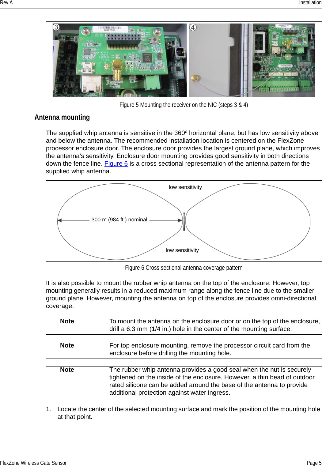
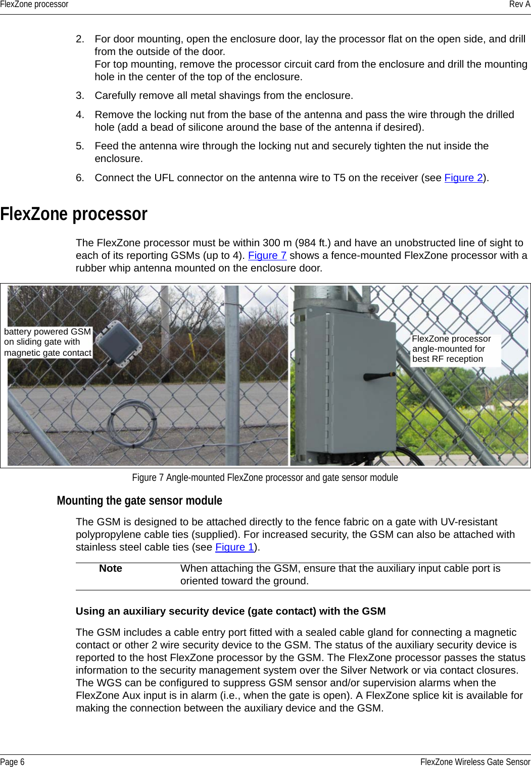
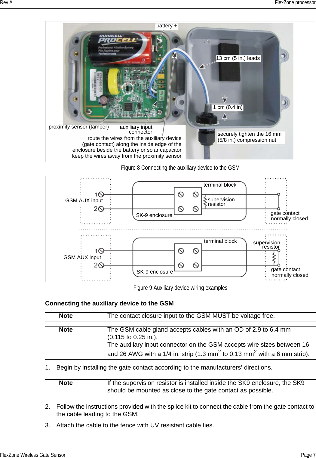
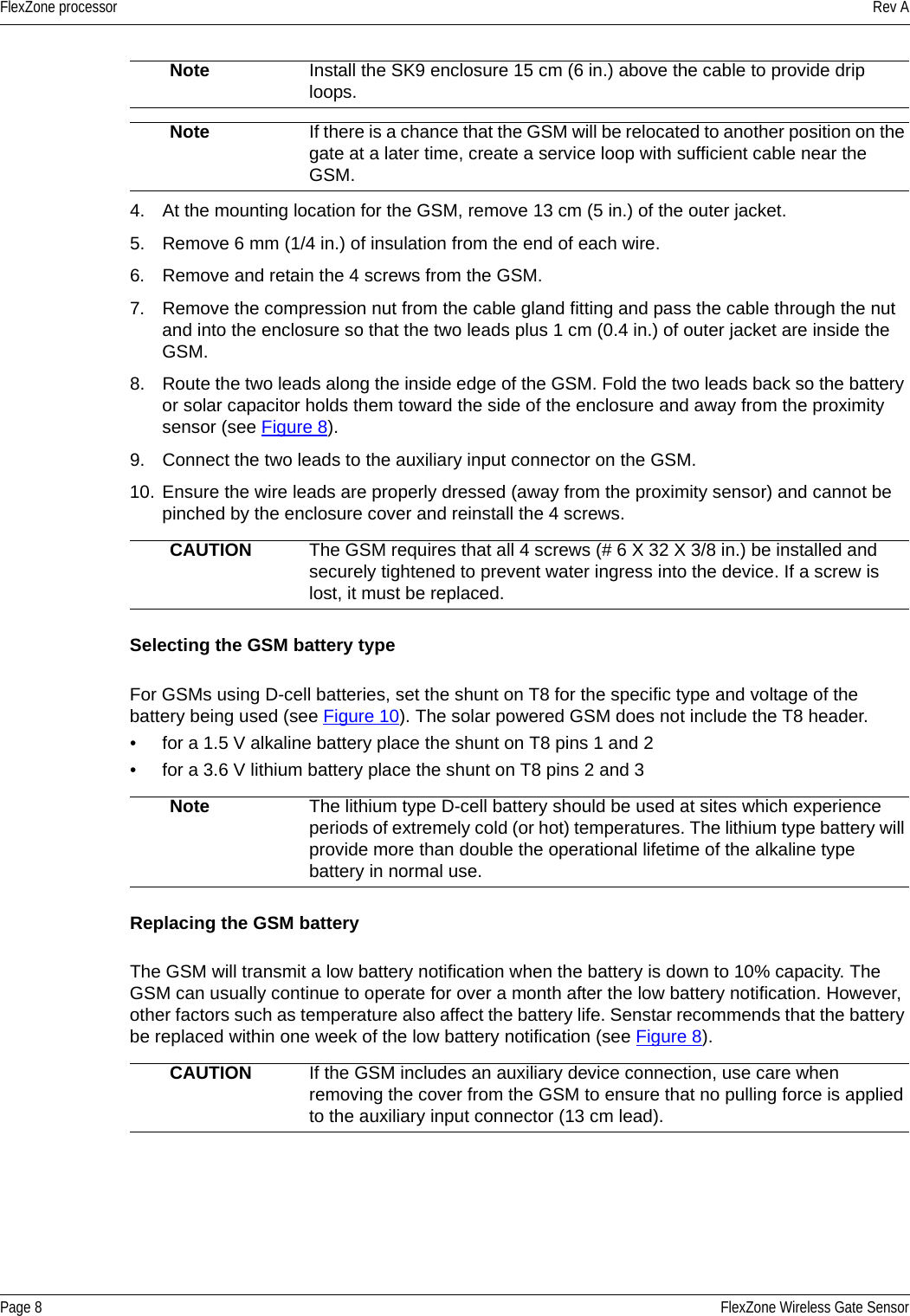
E7BA0300 User Manual
User Manual
Navigation menu
Upload a User Manual
Namespaces
Wiki Guide
HTML
PDF
Info
Views
User Manual
Discussion / Help
Navigation