Senstar T1FG1601 Personal protection device (PPT) User Manual Operator Manual
Senstar Corporation Personal protection device (PPT) Operator Manual
Senstar >
Contents
- 1. User Manual
- 2. User Manual II
User Manual

Flare®
Personal Alarm Location System
Operator
Manual
IP-based sensors
T1DA1702-001, Rev. A
January 19, 2015

Flare® Operator Manual
T1DA1702-001, Rev C Page 2
Senstar Corporation
119 John Cavanaugh Drive
Carp, Ontario
Canada K0A 1L0
Tel: +1 (613)-839-5572
Fax: +1 (613)-839-5830
Website: www.senstar.com
Email address: info@senstar.com
T1DA1702-001, Rev. A
First edition
January 19, 2015
Flare, Senstar and the Senstar logo are registered trademarks, and Flash is a trademark of Senstar Corporation.
Product names and Company names used in this document are included for identification purposes only, and are the
property of, and may be trademarks of, their respective owners. Copyright © 2015, Senstar Corporation. All rights
reserved. Printed in Canada.
Senstar Corporation has prepared the information provided in this guide to the best of its ability. Senstar Corporation
is not responsible for any damage or accidents that may occur due to errors or omissions in this guide. Senstar
Corporation is not liable for any damages or incidental consequences arising from the use of, or the inability to use,
the software and equipment described in this guide. Senstar Corporation is not responsible for any damage or
accidents that may occur due to information about items of equipment or components manufactured by other
companies. Features and specifications are subject to change without notice. Any changes or modifications to the
software or equipment that are not expressly approved by Senstar Corporation void the manufacturer’s warranty, and
could void the user’s authority to operate the equipment.
All material, including technical data, designs, knowledge, and ideas contained in this document are considered
proprietary, and the exclusive property of Senstar Corporation, and shall not be used, disclosed, reproduced, or
transmitted in any form or by any means, electrical or mechanical, including photocopying, recording, or by any
information storage or retrieval system, without permission in writing from Senstar Corporation.
This document is for software versions 1.750 and later.
Senstar Corporation’s Quality Management System is ISO 9001:2008 registered.
Senstar intellectual property is protected by the following patents:
Canada:
2,225,638
U.S.
5,977,913

Flare® Operator Manual
T1DA1702-001, Rev C Page 3
Table of Contents
1.0 INTRODUCTION ............................................................................................................................ 4
1.1 SCOPE ............................................................................................................................................. 4
1.2 APPLICABILITY .................................................................................................................................. 4
1.3 RELATED DOCUMENTATION ............................................................................................................... 4
2.0 SYSTEM OVERVIEW ..................................................................................................................... 5
2.1 PPD ALARMS ................................................................................................................................... 5
2.2 FLARE SYSTEM COMPONENTS ........................................................................................................... 5
2.2.1 Personal Protection Device (PPD) .......................................................................................... 6
2.2.2 Sensor Unit (SU) ..................................................................................................................... 6
2.2.3 Sensor and Test Units (SaTU) ................................................................................................ 7
2.2.4 Central Monitoring Post Computer (CMPC) ............................................................................ 7
2.2.5 PoE switch ............................................................................................................................... 7
2.3 LOCATION INFORMATION ................................................................................................................... 7
2.3.1 Protection Zones (PZones) ..................................................................................................... 8
2.3.2 Calibration Zones (CZones) .................................................................................................... 8
2.4 FLARE SOFTWARE APPLICATION OVERVIEW ....................................................................................... 8
2.4.1 Flare Files Directory Structure ................................................................................................. 8
2.4.2 System Database .................................................................................................................... 9
2.4.3 Configuration Settings File .................................................................................................... 10
2.4.4 Log Files ................................................................................................................................ 10
3.0 SYSTEM OPERATIONS .............................................................................................................. 10
3.1 MAIN OPERATOR SCREEN ............................................................................................................... 11
3.2 ALARM RECEIVED AND LOCATED ..................................................................................................... 12
3.3 ZOOM TO ALARM DISPLAY SCREEN .................................................................................................. 13
3.4 ACKNOWLEDGE ALARM ................................................................................................................... 15
3.5 CLEARING ALARMS ......................................................................................................................... 15
3.6 MULTIPLE ALARMS .......................................................................................................................... 17
3.7 OTHER OPERATOR FUNCTIONS ....................................................................................................... 18
3.7.1 Clear Warning........................................................................................................................ 18
3.7.2 Clear Offsite Alarm ................................................................................................................ 19
3.7.3 Network Reset ....................................................................................................................... 20
3.8 OTHER WARNINGS .......................................................................................................................... 20

Flare® Operator Manual
T1DA1702-001, Rev C Page 4
1.0 INTRODUCTION
Flare is a Personal Alarm Locating System (PALS). Flare detects and locates the activation of small
portable radio frequency transmitters carried by personnel. The system generates location information in
near real-time and can process transmissions in rapid succession. The ID of the transmitter and its
location on a site and floor plan are presented on a PC display.
Flare is designed to identify the location of personal portable transmitters to within one of a number of
predefined Protection Zones into which the facility has been partitioned. The system is comprised of RF
receivers strategically positioned within the facility to measure the signal strengths of RF transmissions.
These measurements are correlated with previously recorded data using refined locating algorithms using
radio frequency propagation modeling tools. The transmission is predicted to have originated from within
the zone whose modeled values most closely match those of the transmission. A map of the facility is
presented with the location of the alarm transmission highlighted.
1.1 Scope
The purpose of the Flare Operator manual is to provide an overview of Flare and its components, a
description of the Flare system operations, and a guide to the Flare user interface and alarm processing.
This manual is intended for individuals who will be acknowledging and processing alarms.
1.2 Applicability
This manual is specific to Flare software version 1.750 and later, which communicate through the Krypton
Network Manager.
1.3 Related Documentation
The Flare System Administrator Manual (T1DA1602-001)
Describes Flare system management, configuration and database creation and calibration.
Intended for the Flare system administrator.
The Flare Maintenance Manual (T1DA1502-001)
This describes the methods for maintaining the Flare system, including preventive and corrective
maintenance procedures. Intended for technical personnel, responsible for the maintenance and repair of
the Flare System.
The Flare PPD Manual (T1DA0502-001)
Provides configuration and setup details for the Flare Personal Protection Device (PPD).

Flare® Operator Manual
T1DA1702-001, Rev C Page 5
2.0 SYSTEM OVERVIEW
The Flare Personal Protection Device (PPD) is a small, portable belt-worn UHF transmitter that is
assigned to facility personnel such as correctional officers and health care professionals. Flare
transmitters are also available as Fixed Point Alarms such as panic and duress buttons. In alarm
situations the PPD is activated and transmits a signal, which is received, decoded, and processed by a
distributed network of RF receivers (sensors). The data from the sensors is then forwarded to the Flare
Central Monitoring Post Computer (CMPC) where the data is analyzed and the location of the transmitter
is determined. The location of the alarm is displayed on a facility map presented on the Flare PC. The
Flare alarm data can also be communicated to a third party security management system (SMS).
2.1 PPD Alarms
Push-Button
The PPD transmits an alarm message when the red push-button switch is pressed.
Low Battery
The PPD automatically transmits a low battery message when the battery drops below a certain voltage.
Each subsequent activation of the PPD will retransmit the low battery message.
PPD Transmitters may be also equipped with one or more of the following optional methods of activation:
Man-Down (Tilt)
The PPD transmits an alarm message when the unit is tilted beyond a specified angle for a preset period
of time. The tilt angle, and delay time are administrator programmable.
Tamper (Lanyard)
The PPD transmits an alarm message when a pull-pin is removed from the unit. The pull-pin lanyard is
typically looped through the wearer’s belt and the pin is pulled out if the PPD is forcibly removed from the
wearer.
2.2 Flare System Components
The Flare system is typically comprised of the following components:
PPD Personal Protection Device: RF transmitter, aka. Personal Portable Alarm (PPA) also available as
wireless fixed point alarms (panic or duress buttons)
SU Sensor Unit: an RF receiver, aka. Sensor
SaTU Sensor and Test Unit: a sensor that is also equipped with a PPD type transmitter to test nearby
system receivers
CMPC Central Monitoring Post Computer: the Flare s/w application PC
PoE Power over Ethernet: network communication switch and power supply for SU’s and SaTU’s
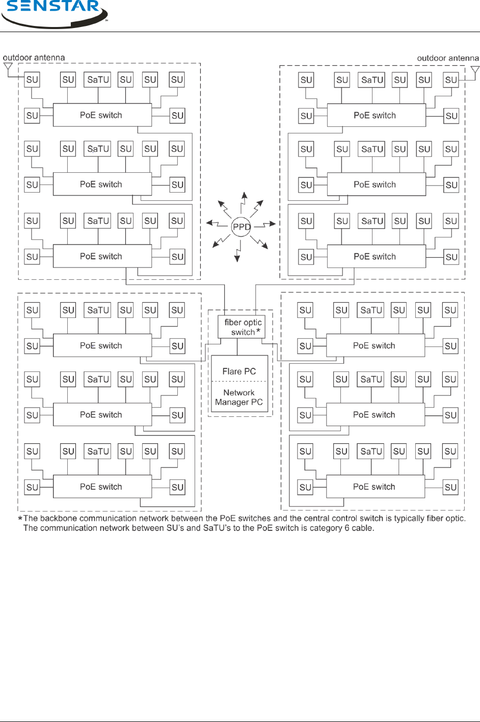
Figure 2.2 is a block diagram of a Flare system covering four three level buildings and a large outdoor
area.
Flare® Operator Manual
T1DA1702-001, Rev C Page 6
Figure 2.2 – Conceptual Flare System Block Diagram
2.2.1 Personal Protection Device (PPD)
The PPD is an RF transmitter that transmits an administrator programmable modulated code ID when
activated. Optionally, the PPD can include man down and pull pin activation. It also transmits a low
battery alarm when its battery voltage drops below a certain voltage. PPD IDs range from 0-4095.
2.2.2 Sensor Unit (SU)
The sensor unit consists of an RF receiver, microprocessor, and Ethernet communications interface.
Flare installations typically include 100 to 300 sensors, which are strategically distributed throughout the

Flare® Operator Manual
T1DA1702-001, Rev C Page 7
facility. When an SU detects a PPD alarm transmission, it measures the strength of the received signal
and provides a normalized Received Signal Strength Indicator (RSSI). A single PPD transmission is
received by many SUs, which, through the Network Manager, provide RSSI information to the Flare
software for location analysis. Each sensor is connected to a class 3 PoE switch, and each sensor must
be located within 100 m (328 ft.) of that switch. Typically, Flare systems include multiple PoE switches,
which are in turn connected to a central switch located in the control room. The PoE switches are usually
connected to the central switch via fiber optic cable.
2.2.3 Sensor and Test Units (SaTU)
The Sensor and Test Unit (SaTU) is a sensor unit that is equipped with a PPD based transmitter. The
SaTU is used to verify the system’s receivers are functioning properly. During system tests, the Flare
software activates the SaTU PPD. The Flare software verifies that nearby sensors received the SaTU
transmission and compares the results to previously recorded RSSI levels.
2.2.4 Central Monitoring Post Computer (CMPC)
The Flare software application runs on the CMPC, which is a PC running a Windows-based operating
system. The Flare CMPC communicates with the distributed devices via the Krypton Network Manager. It
controls the operations of the other system components and applies the locating algorithm on the signal
strength measurements received from sensors during an alarm event. The Flare software determines the
location of the PPD alarm transmissions and presents the alarm location to the user on graphics layouts
of the facility. An audible alarm is also generated upon receipt of an alarm. If the facility is so equipped,
the CMPC can also output alarm location messages to an external security management system over a
Starcom or DWI protocol EIA-232C serial channel. The Flare software provides functions to configure the
system, calibrate the system, set or modify various system parameters, and conduct various system
diagnostic tests.
2.2.5 PoE switch
The Flare sensors are powered by, and communicate through a class 3 PoE switch. Each connected
sensor must be located within 100 m of its PoE switch, and Category-6 wiring is required. When multiple
PoE switches are used at a site, they are usually connected to a central switch located in the Control
Room. The CMPC is also connected to the central switch as is the Network Manager PC and the UCM
PC. Note that the Network Manager and UCM applications can reside on the CMPC (Flare computer).
2.3 Location Information
When an alarm occurs, Flare determines the location of the PPD transmission and highlights this location
on a graphical representation of the facility floor plans. A text message at the bottom of the main operator
screen indicates the PPD ID of the transmitter, the PPD alarm type and the description of the location.
The facility locations are defined within the Flare database by building, floor system, protection zone and
calibration zone. The protection zones (PZones) are logical groupings of location points called calibration
zones (CZones). When an alarm occurs, a building outline is presented on the site layout. When the
building is selected the PZone outline is presented on the zoomed-in floor plan with the CZone
highlighted.

Flare® Operator Manual
T1DA1702-001, Rev C Page 8
2.3.1 Protection Zones (PZones)
Protection Zones typically represent logical and physical groupings of rooms and other areas within the
facility. Examples include: Cell Block B, Administration First Floor, Food Service - Dining Room, Outdoor
Zone 3, Building 1 - A Wing, etc. Flare database creation and PZone definition require knowledge of Flare
function and must suit the facility’s needs.
2.3.2 Calibration Zones (CZones)
A calibration zone (also referred to as a calibration point) identifies a specific location within the Protection
Zone where the alarm was located. The placement and quantity of calibration zones play a major role in
setting the accuracy and resolution of the system. Flare database creation and CZone definition require
in-depth knowledge of Flare functionality, and ensure that the system meets the facility’s defined
specifications.
2.4 Flare Software Application Overview
This section provides an overview of the files that comprise the Flare software system. The Flare software
system has two main elements:
Application Software (FlareVxxxx.exe, xxxx = the version) and configuration settings file (Flare.ini)
System Database: floor layout files (*.emf ) calibration data files for dbas type 0 = *.arc, dbas or for
type 1 = *.mdb
2.4.1 Flare Files Directory Structure
Flare system software and support files are contained in a local disk (C:) folder named Flare, or
FlareVxxxx (with the version number appended, e.g., FlareV1734). The following example uses the name
Flare, resulting in a folder C:\Flare.
C:\Flare\
FlareVxxxx.exe
Flare.ini
prison1\
map files (prison1.emf and floor system emf files)
current\
type 0 database and calibration arc files (including prison1.arc)
type 1 database and calibration mdb file
logs\
OPS logs
DIAGS logs
ALRMS logs
SaTU_test_data\
Contains SaTU test data log files.
The ini setting MapPath determines the map folder and sitename, this sets the main map
(site plan) emf filename and main database file. For the default site name, prison1, the map folder is

Flare® Operator Manual
T1DA1702-001, Rev C Page 9
C:\Flare\prison1, the main map emf is C:\Flare\prison1\prison1.emf and the main database file is
C:\Flare\prison1\current\prison1.emf.
However, with FlareV1710 and later the file structure can be customized using the new ini file settings for
sitename, MapPath (e.g., C:\Flare\sitename\maps) and ArcPath
(e.g., C:\Flare\sitename\arcs) for a more definitive structure:
C:\Flare\
FlareVxxxx.exe
Flare.ini
sitename\
maps\
map files (sitename.emf and floor system emf files)
arcs\
type 0 database and calibration arc files (including sitename.arc)
type 1 database and calibration mdb file
logs\
OPS logs
DIAGS logs
ALRMS logs
SaTU_test_data\
Contains SaTU test data log files
Ophex\ (Device firmware files)
SystemInfo\ (Device data files)
2.4.2 System Database
The database consists of two types of files: map files and data files.
Map Files
The map files are enhanced metafile format (.emf). There is one file for the main site map and as many
other files as required for all floors of each building and the outdoor zones that make up the Flare locating
coverage area. The sitename is user defined in the Flare.ini file and it determines the main map (site
plan) emf filename. The indoor floor layout file names are in the format Buildingname_Floorlevel.emf. The
outdoor protection zone map file names are in the format Zonename_.emf.
The building names, floor names, and zone names that the Flare application uses in database setup and
definition will appear as in these user-defined file names. There must be a map file present in the map
directory for each building floor level and each outdoor protection zone BEFORE the system setup can
begin.
Data Files
A database uses either of two file types to store hardware configuration and calibration data.
Type 0 – arc file types:

Flare® Operator Manual
T1DA1702-001, Rev C Page 10
The arc files are stored in a single folder. For the default site name, prison1, the main database arc file is
prison1.arc. The arc files contain PZone information and PZone calibration data. There is one file per
PZone.
Type 1 – mdb file:
The mdb file holds all PZone and calibration data. The default file naming convention is
sitename_yymmdd.mdb.
2.4.3 Configuration Settings File
The file C:\Flare\Flare.ini contains various configuration parameters for the Flare system. System
configuration issues are addressed in detail in the Flare Technical Manual. This file is read at Flare
software startup and its parameters are typically presented in the System Configuration screen. This file
format has changed occasionally with new Flare application software versions. Upon s/w upgrades the
safe upgrade process is to edit the site specific configurations into the ini file supplied with the Flare
application, which has the default values.
2.4.4 Log Files
During operation the Flare system automatically generates various log files including:
Operations Log: Alarm events, configuration changes.
Default name: PALS-OPS-YYMM.log
Diagnostic Log: Self Test results, system error/warning messages
Default name: PALS-DIAGS-YYMM.log
Alarm Log: All sensors RSSI data for alarms.
Default name: PALS-ALRMS-YYMM.log
SaTU Log: Contained in a log folder subdirectory called SaTU_test_data.
SaTU_xxx_curr.log is the current SaTU test data log. SaTU_xxx_yyyymmdd_a.log is an SaTU test data
log from calibration period starting on yyyymmdd.
3.0 SYSTEM OPERATIONS
The CMPC operator console is a PC with a Windows operating system running Flare application
software. Flare software communicates with the distributed Flare hardware devices and provides a
graphical user interface for the operator and maintenance technician to perform all necessary Flare
operations. The application can be launched by clicking on a Flare shortcut on the system desktop, or on
the Flare executable file in the current Flare folder. There should also be a Flare shortcut in the startup
menu to automatically launch the Flare software at PC power-on and boot up. It can take several minutes
for the system database to load and the system to initialize.
After initialization the system enters normal operating mode providing alarm monitoring and graphical
display. This main operator screen typically shows a graphical overall site plan and an event message
display. All alarm functions are presented in this mode, exit of operator mode into administrator functions
is through password access. Entry of the user password allows access to selected maintenance
functions.
The balance of this document will present the screen conditions that an operator will encounter during the
operation and testing of Flare. Instructions regarding the appropriate responses to alarm and warning
conditions will be provided as well.

Flare® Operator Manual
T1DA1702-001, Rev C Page 11
3.1 Main Operator Screen
Figure 3.1 presents the operator screen in the normal mode. Here, no alarms or warnings have been
received and the system is stable (required hardware is functional).
Refer to the message box, which contains the columns Date/Time, Type, and Message.
Date/Time: Presents the date and time when the system activity occurred.
Type: Three types of messages are presented on the operator screen:
1 Note: System status information which requires no action by the operator, e.g.,
the start and end notifications of automatic self-tests.
2 Warning: Warning messages reflect potential maintenance issues and may require
the operator to alert facility maintenance staff, e.g., low battery or system
unstable warnings.
3 Alarm: Alarms indicate that a PPD activation has been detected.
Message: Presents the pertinent details of the system activity. In the case of an alarm, the type of
activation, ID of the transmitter, and its location is presented in this field.
When the list of text messages exceeds the space available, a scroll bar appears on the right side of the
message box and the earlier received messages scroll off the screen. These messages can be reviewed
by clicking the mouse on the up and down arrows or by dragging the scroll bar. The operator cannot
delete or alter any messages from the message box – these are permanently stored in system memory
and on hard disk.
Flare® Operator Manual
T1DA1702-001, Rev C Page 12
Figure 3.1 - Operators Screen Normal Operations
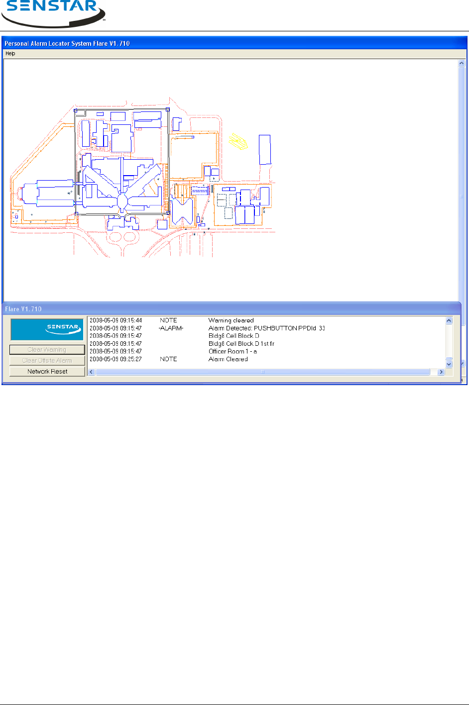
3.2 Alarm Received and Located
When an alarm is received an audible alert will sound and the alarm type and PPD ID and descriptions (if
defined and enabled) will be listed in the message box. Next the alarm location is resolved and is
presented as a red outline around the building or out door zone on the site plan. Figure 3.2 presents the
operator screen when an alarm has been received and located. The resolved alarm location information
will be listed as well as a building name, Protection Zone and Calibration Zone.
Flare® Operator Manual
T1DA1702-001, Rev C Page 13
Figure 3.2 - Operators Screen Alarm Received
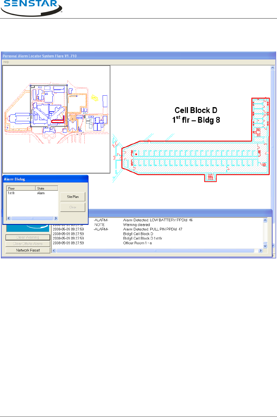
3.3 Zoom to Alarm Display Screen
The display zoom in is activated by clicking the left mouse button inside the highlighted outline of the
building or out door zone in alarm. This zoom in alarm display screen presents the Protection Zone and
Calibration Zone of the resolved alarm location.
Protection Zones are typically defined by personnel access and response team path. For the example
shown below, the cell block floors of each building are defined as separate zones since moving from one
to another requires returning to a common stairwell. Protection Zones can be either indoors or outdoors.
Calibration Zones or points, are located in specific rooms in the case of indoor Protection Zones and are
usually grid-based positions in the case of outdoor Protection Zones. The location of these Calibration
points are presented graphically when the operator requests the system to zoom in to the location of the
alarm.
Calibration Zone points can be identified by a room number or name, stairwell, corridor or area name,
typically followed by a letter to denote multiple points within that area name. The operator should omit the
letter information when alerting response teams. In the case of outdoor Protection Zones, the calibration
point name can be a unique alphanumeric sequence, which does not provide more specific location
information. In this case the sub-zone specific information can be derived only from the location depicted
on the graphical display. Typically outdoor resolution is less than indoor resolution but the increased line
of sight helps with alarm response evaluation.
Flare® Operator Manual
T1DA1702-001, Rev C Page 14
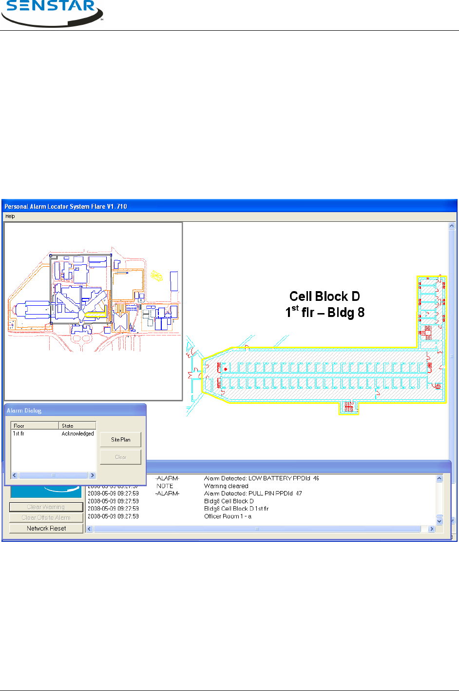
Figure 3.3 shows the zoomed in alarm display. The system zooms in to present the Protection Zone
under alarm and indicates the Calibration Zone point (red dot) resolved closest to the origin of the alarm
transmission. The alarm audible alert sound is still active – the alarm has not yet been acknowledged as
indicated by the fact that the Protection Zone is still outlined in red.
Figure 3.3 - Alarm Display Screen - Alarm Active
A smaller view of the site plan is still shown on the left side of the screen. This minimized site plan
provides the operator with a reference view of the whole facility and also indicates to the operator of other
area alarms and their statuses by building outline colour.
The Alarm Dialog box has also appeared. This box tells the operator the floor system and status of the
current system alarms and allows the operator to return to the full screen site plan. At any time, the
operator may return to the full screen site plan by clicking on the Site Plan button in the Alarm Dialog box
– even if current alarms have not yet been acknowledged or cleared. Alarm processing colour scheme is
as follows:
Building and Protection Zone Outline Status Colors:
Red Alarm is active. Alarm sound is active.
Yellow Alarm is acknowledged. Alarm sound is silenced.
Green Alarm is clearable.
None Alarm has been cleared.
Flare® Operator Manual
T1DA1702-001, Rev C Page 15
3.4 Acknowledge Alarm
The active alarm is acknowledged when the operator clicks the left mouse button within the red
highlighted Protection Zone. The audible alert alarm sound will cease. The highlight has changed from
red to yellow on both the zoomed in PZone view and on the minimized site plan building outline
(Figure 3.4).
At this time, the operator should dispatch the response team to the location shown on the screen. The
calibration point shown is the closest match to the actual alarm recorded in the Flare database and
should be inspected first. However, the actual alarm location could be different from this point shown so
the response team should inspect in all directions from this point and continue moving outwards until the
source of the PPD alarm transmission is located.
Figure 3.4 - Alarm Display Screen - Alarm Acknowledged
3.5 Clearing Alarms
When the response action is complete, the alarm is made clearable by the operator clicking the left
mouse button within the yellow highlighted Protection Zone. The highlight has changed from yellow to
green on both the zoomed in PZone view and on the minimized site plan building outline (Figure 3.5).
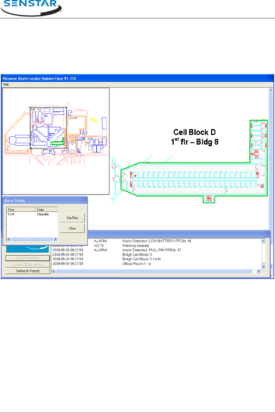
Flare® Operator Manual
T1DA1702-001, Rev C Page 16
A Clear button is now available in the Alarm Dialog Box and the alarm state is shown as clearable.
Selecting this button completes the alarm processing, and the green outlines are cleared.
The operator may return to the full screen site plan by clicking the left mouse on the Site Plan button in
the Alarm Dialog box. The message box will contain the chronological log of all alarms, active and
cleared.
Figure 3.5 - Alarm Display Screen - Alarm Clearable
Flare® Operator Manual
T1DA1702-001, Rev C Page 17
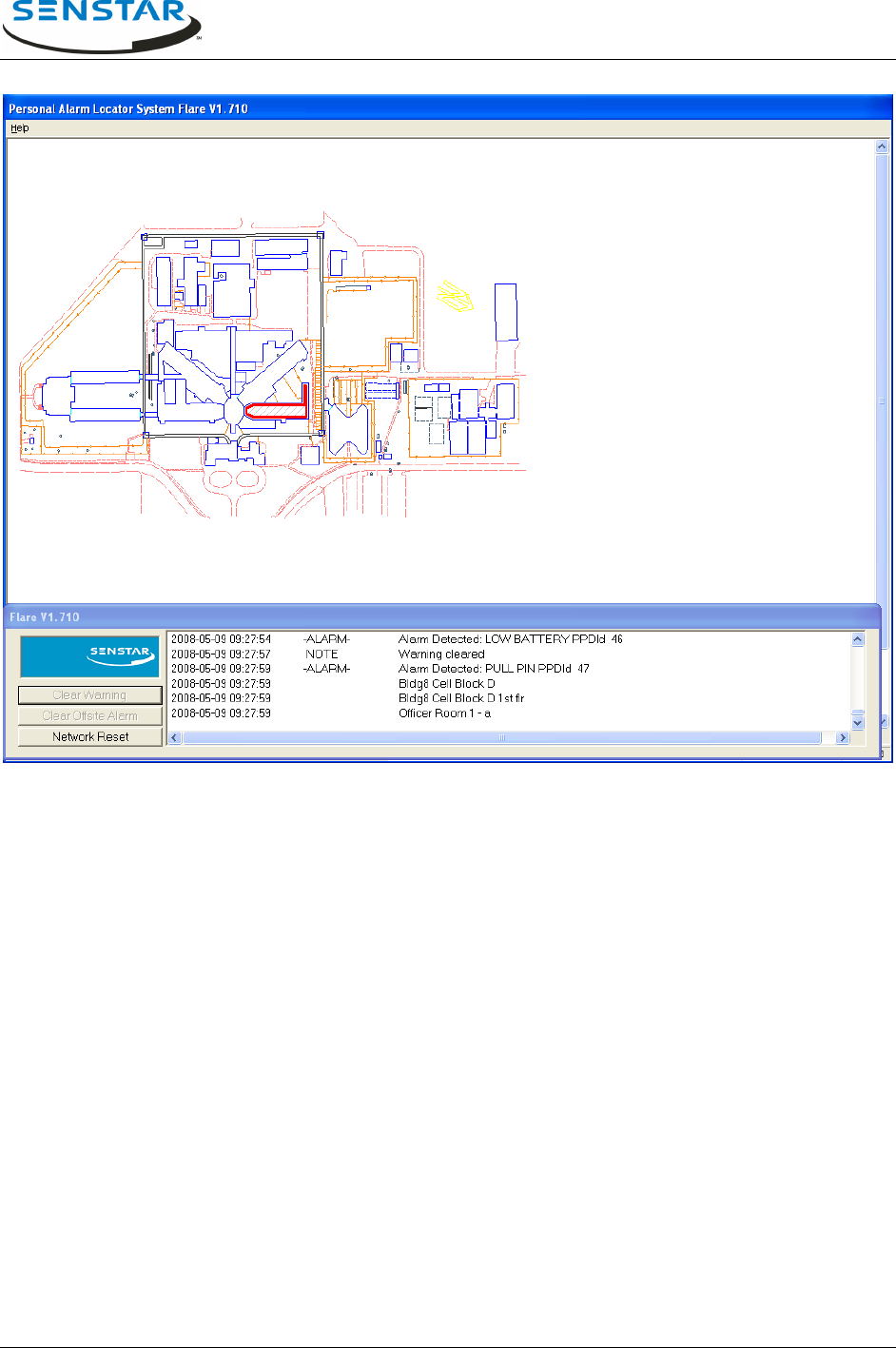
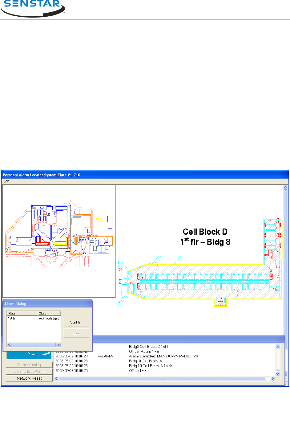
3.6 Multiple Alarms
Multiple alarms can occur, originating from the same or a different Protection Zone. In the case of the
same PZone another Calibration Zone point is displayed on the zoomed-in alarm display screen and the
Protection Zone alarm state returns to active. Figure 3.6 shows the screen that is displayed when a
second alarm is received from a different PZone while the operator is zoomed in to process a current
alarm. Notice that a second building is now highlighted in the minimized site plan. The alarm sound will
begin again to indicate that a new alarm has been received. The message box lists the new alarm
information for the operator to view. In the example there is a different alarm type – MAN DOWN, a tilt
detection.
The operator can choose to continue to process the current alarm or to immediately zoom-in to respond
to the new alarm by clicking on the new alarm building outline in the minimized site plan or in the full size
site plan by first selecting the Site Plan button. The operator can switch between zoomed-in Protection
Zone alarm screens and process each independently. As with single alarms, the outlines for each alarm
state are maintained in both the PZone and building outline in the minimized site plan.
Figure 3.6 - Multiple Alarms in Different PZones
Flare® Operator Manual
T1DA1702-001, Rev C Page 18
3.7 Other Operator Functions
There are three buttons on the lower left of the operator screen (Figure 3.2). These provide processing of
other system events.
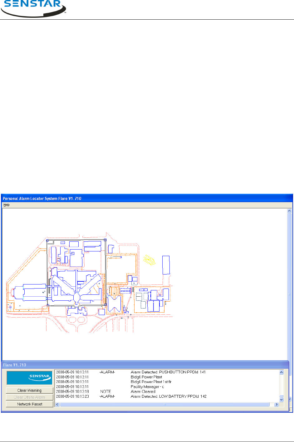
3.7.1 Clear Warning
Low Battery Warning
When a PPD detects its battery condition is low, it automatically activates a low battery warning
transmission. This condition is listed in the message box showing the alarm type as low battery and the
PPD ID of the unit (Figure 3.7.1) and an audible alarm will be annunciated. To clear the alarm, click on
the Clear Warning button on the bottom left corner of the screen.
When a low battery warning message is received, the wearer of that PPD should be notified and the PPD
taken out of service until its battery can be replaced by maintenance.
During the battery low condition, each time this transmitter is activated it will send two alarm messages.
The first will be for the alarm event (push button, pull-pin, or man-down) and the second will be a
reminder that the unit has a low battery condition.
Figure 3.7.1 - Low PPD Battery Warning

Flare® Operator Manual
T1DA1702-001, Rev C Page 19
System Unstable Warning
The Flare system regularly performs background self-tests of all elements of the system. The Minor Self
Test (MiST) and Major Self Test (MaST) events are listed in the message box when they occur. Any
resulting minor error conditions are not displayed on the main operations screen and are instead logged
to a maintenance diagnostic file. The diagnostic file can be reviewed by a maintenance technician to
verify that there is no persistent or accumulated minor errors.
If the MiST determines that a certain defined amount of hardware has stopped responding, a Flare
System Unstable fault condition is declared and an audible alert will sound. This alert is silenced with the
Clear Warning button. If an unstable condition occurs, the operator procedure may be to alert the
maintenance staff or to evaluate the severity of the warning. To review the conditions causing the warning
the operator may be given access to the diagnostics function to run a manual MiST, which will indicate
the number of devices that are not responding.
If no corrective action is taken, the unstable condition is likely still active and will re-occur upon the next
MiST. When the condition is active, alarm location accuracy and even detection (if much hardware is off-
line) will be degraded in the areas supported by the affected hardware.
There may be procedures that active users should be notified immediately and the system removed from
service. Maintenance personnel should be contacted and a pre-designated System Down plan
implemented.
3.7.2 Clear Offsite Alarm
Off-site alarms are alarms, which originate from PPD transmitters, which have been registered for use
only at specific off-site locations. When a transmission ID is detected from one of these PPDs, the Flare
system does not attempt to resolve the location using the normal locating algorithm and no graphical
location is presented. Instead, the location presented in the message box is a pre-defined text description
of where the PPD was designated for use and an audible alert will sound. No matter where that ID PPD
actually is, the system will report alarms originating from that ID as having come from the off-site
description that it was issued. Therefore, it is imperative that off-site PPD transmitters are only used at
their off-site locations.
To process an off-site alarm, follow procedures for the response to the described location. To clear it,
click on the Clear Offsite Alarm button.
Off-site alarms are typically used to cover extra fringe areas where a PPD transmission can be reliably
detected but there may not be enough responding sensors to deliver the required location accuracy.
Despite the name, these may not be actually off-site areas.
The System Administrator may designate PPD IDs 1045 to 1049 for use outside the perimeter fence.
Likewise, they assign IDs 1050 to 1055 for use on the facility roof. Then, when an officer or staff member
needs to access the roof, they should carry with them a PPD in the range of 1050 to 1055. If they
encounter trouble and press the button on the PPD, the system will display an off-site alarm from
ID 1050 - ROOF. Similarly, if PPDs 1045 to 1049 are activated, the system will display ID 1045 - Outside
Fence.

Flare® Operator Manual
T1DA1702-001, Rev C Page 20
3.7.3 Network Reset
This button will cause reset messages to be broadcast throughout the Flare hardware network. This will
soft reboot all devices that receive the communication and remove all queued alarm and stored device
statuses. This is very similar to the reset performed at system initialization. This can be used when
sensor(s) communications are restored and the sensors have old alarms queued. This function will
invalidate any current alarm location processing. It should not be used on potentially valid alarm events.
3.8 Other Warnings
Two other warning messages can appear in the message box. These will not be accompanied by an
audible warning tone. The system clears these conditions automatically without any action required by the
operator. Here is sample text for these warnings:
2014-05-08 17:19:51 | WARNING | Single-sensor alarm - cleared. Sensor 12, PPD ID = 791
2014-05-08 17:19:57 | WARNING | Invalid PPDId - cleared: Sensor Address = 16
Single-sensor alarm:
The Flare system requires two of its sensors to receive a PPD transmission to declare a valid alarm for
locating. If only one sensor reports an alarm it is usually because that one sensor is late reporting an
alarm event that has just been processed. The PPD ID is listed to help evaluate the event. The sensor is
listed so that if there are persistent single sensor alarms from a particular sensor then this sensor
condition can be reported to maintenance for review.
Invalid PPD ID:
The invalid PPD ID value of 65535 can indicate a PPD ID modulation was decoded by a sensor, but the
ID did not fall within the range programmed into that sensor.
It can also indicate that a sensor has received an un-modulated transmission (a signal without a PPD ID).
These conditions should be reported to maintenance for review.