Sensus Metering Systems 100A OMNI Communicator User Manual Manual
Sensus Metering Systems Inc. OMNI Communicator Manual
Manual

5015 B.U. Bowman Drive Buford, GA 30518 USA Voice: 770-831-8048 Fax: 770-831-8598
Certification Exhibit
FCC ID: SDB100A
IC: 2220A-100A
FCC Rule Part: 15.209
IC Radio Standards Specification: RSS-210
ACS Report Number: 09-0031 - 15C
Manufacturer: Sensus Metering Systems, Inc.
Model: 100A
Users Manual


Revisions
This document contains proprietary information. It is to be used only for the purpose for which it is intended.
Information in this document is subject to change without notice and does not represent a commitment on the part
of Sensus Metering Systems-North America, Inc. No part of this publication may be reproduced, transmitted,
stored in a retrieval system, or granulated into any language in any form by any means, without the written
permission of Sensus.
© Copyright 2009, Sensus. All Rights Reserved.
Sensus and associated logos are trademarks of Sensus and its subsidiaries and affiliates. All other brand names
may be trademarks of their respective owners.
Sensus
1501 Ardmore Boulevard, Suite 601
Pittsburgh, PA 15221 USA
1-800-METER-IT (638-3748)
1-800-888-2403 (fax)
www.sensus.com
Document:
UniPro/OMNI Communicator Model 100A
Document Number:
WRMTM-40000
Rev No. Date Description
Rev 1 1/28/2009 Iniital release
Warning: Changes or modifications to this device not expressly approved by Sensus Metering
Systems could void the user’s authority to operate the equipment.
NOTE: This equipment has been tested and found to comply with the limits for a Class B digital
device, pursuant to Part 15 of the FCC Rules. These limits are designed to provide reasonable
protection against harmful interference in a residential installation. This equipment generates,
uses, and can radiate radio frequency energy and, if not installed and used in accordance with
the instructions, may cause harmful interference to radio communications. However, there is
no guarantee that interference will not occur in a particular installation. If this equipment does
cause harmful interference to radio or television reception, which can be determined by turning
the equipment off an on, the user is encouraged to try to correct the interference by one or more
of the following measures:
• Reorient or relocate the receiving antenna.
• Increase the separation between the equipment and receiver.
• Connect the equipment into an outlet on a circuit different from that to which the
receiver is connected.
• Consult the dealer or an experienced radio/TV technician for help.
This equipment complies with FCC radiation exposure limits set forth for an uncontrolled
environment. This equipment is in direct contact with the body of the user under normal
operating conditions. This transmitter must not be co-located or operating in conjunction with
any other antenna or transmitter.
The term “IC:” before the radio certification number only signifies that Industry Canada technical
specifications were met.
This Class B digital apparatus meets all requirements of the Canadian Interference Causing
Equipment Regulations. Operation is subject to the following two conditions: (1) this device
may not cause harmful interference, and (2) this device must accept any interference received,
including interference that may cause undesired operation.
Cet appareillage numérique de la classe B répond à toutes les exigences de l’interférence
canadienne causant des règlements d’équipement. L’opération est sujette aux deux conditions
suivantes: (1) ce dispositif peut ne pas causer l’interférence nocive, et (2) ce dispositif doit
accepter n’importe quelle interférence reçue, y compris l’interférence qui peut causer
l’opération peu désirée.

Table of Contents i
UniPro/OMNI Communicator Model 100A WRMTM-40000
Table of Contents
1 Overview of UniPro ............................................................................................................ 1-1
2 Hardware Setup.................................................................................................................. 2-1
2.1 Attaching the Hardware ............................................................................................................2-1
2.2 Setting the COM Port ................................................................................................................2-1
3 Programming an OMNI T2/C2/F2 Register....................................................................... 3-1
4 Setting Meter Defaults ....................................................................................................... 4-1
4.1 Defaults Screen ........................................................................................................................ 4-1
4.2 Setting Turbo2e/OMNI Defaults ................................................................................................4-2
4.3 Setting ICE Defaults ..................................................................................................................4-7
4.4 Setting Miscellaneous Defaults ............................................................................................... 4-12
5 Data Log.............................................................................................................................. 5-1
6 Reports................................................................................................................................ 6-1
6.1 Opening a Report ......................................................................................................................6-1
6.2 Printing a Report .......................................................................................................................6-2
7 Error Log............................................................................................................................. 7-1
7.1 Viewing and Acknowledging Errors ..........................................................................................7-1
Overview of UniPro 1-1
UniPro/OMNI Communicator Model 100A WRMTM-40000
1 Overview of UniPro
The UniPro application programs, logs data from, and tests T2/C2/F2meters. Versions of the software have been
created for both a laptop PC and the Sensus AR5000 Handheld/AutoRead.
A separate hardware interface device (communicator 100A) allows the meter to be read, etc. using the laptop’s
USB port and the AR5000’s serial port.
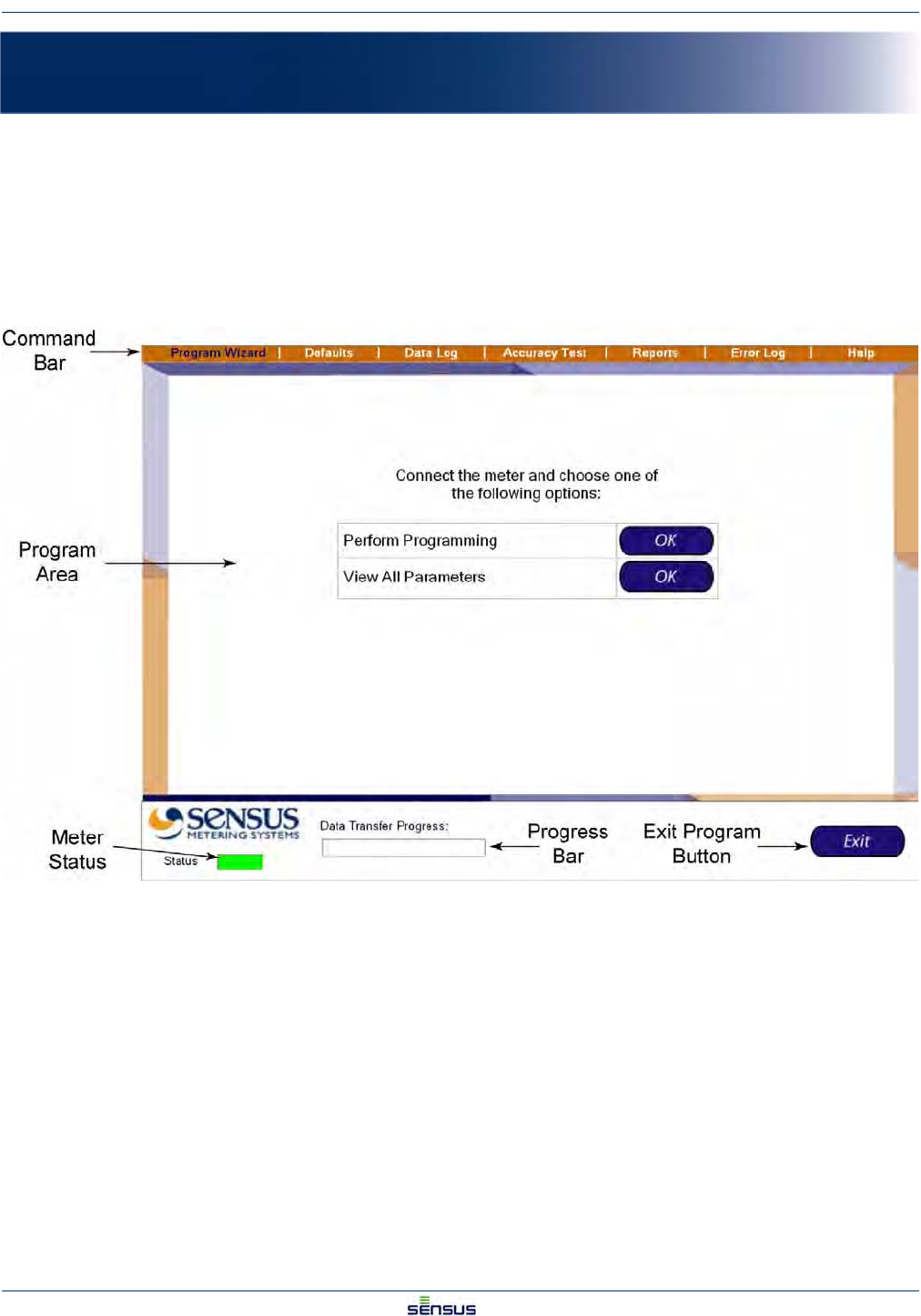
Figure 1-1shows the basic screen for the UniPro software.
Figure 1-1: Screen Layout for UniPro
Command Bar: Contains the commands to open the various program elements.
Program Area: Displays the program elements.
Meter Status: Green indicates the meter is properly linked; red indicates the meter is not properly linked.
Progress Bar: When data is read from the meter, the progress bar indicates the progress of the transfer.
Exit Program Button: Select the Exit button to end the program.
Hardware Setup 2-1
UniPro/OMNI Communicator Model 100A WRMTM-40000
2 Hardware Setup
2.1 Attaching the Hardware
1. Attach the USB connector from the OMNI Communicator 100A to any available USB port on your
laptop.
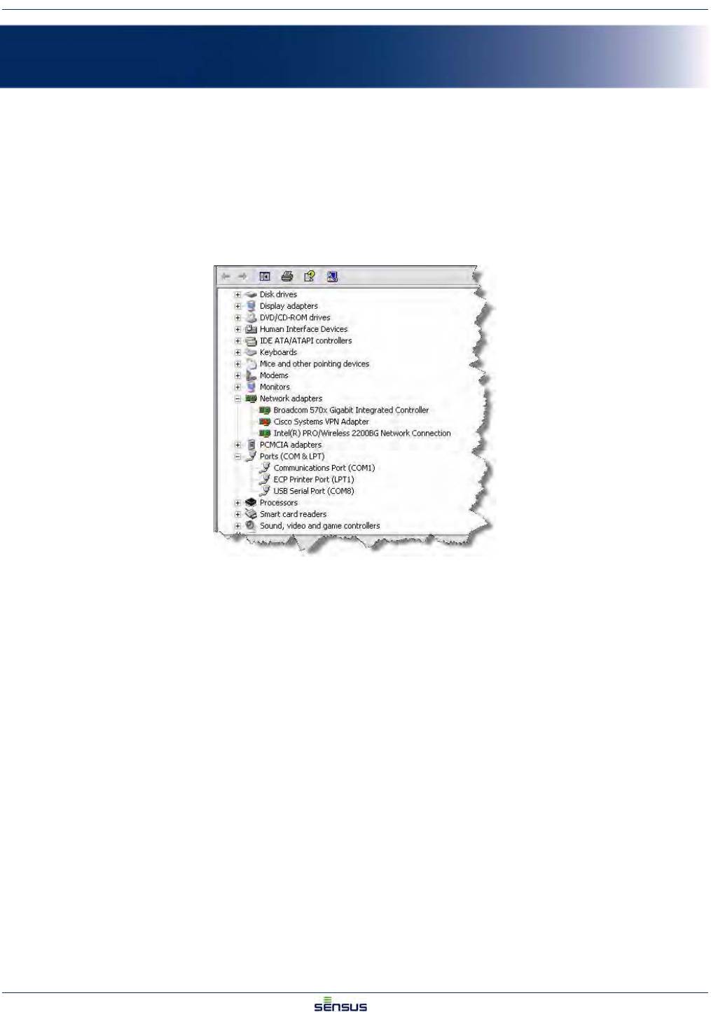
2. Check your Device Manager to determine the USB port’s Com Port designation.
3. Select Start→Control Panel→System→Hardware Tab→Device Manager.
The Device Manager window looks similar to the one shown in Figure 2-1.
Figure 2-1: Typical Device Manager Window
4. Select Ports in the list and note the USB Serial Port COM assignment (COM8 in the illustration).
2.2 Setting the COM Port
1. Double-click on the UniPro icon on your desktop.
The UniPro Program Wizard screen is displayed (see Figure 2-2).
Hardware Setup 2-2
UniPro/OMNI Communicator Model 100A WRMTM-40000
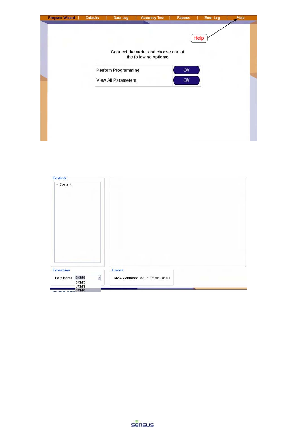
Figure 2-2: Selecting Help
2. Click Help in the Menu Bar.
The Help/Communications Port screen is displayed as shown in Figure 2-3.
Figure 2-3: Help/Connection Screen
3. In the lower left corner, in the Connection partition, select the proper COM port from Step 4 of
Section 2.2.
4. Click Program Wizard to return to the Program Wizard screen.
Programming an OMNI T2/C2/F2 Register 3-1
UniPro/OMNI Communicator Model 100A WRMTM-40000
3 Programming an OMNI T2/C2/F2 Register
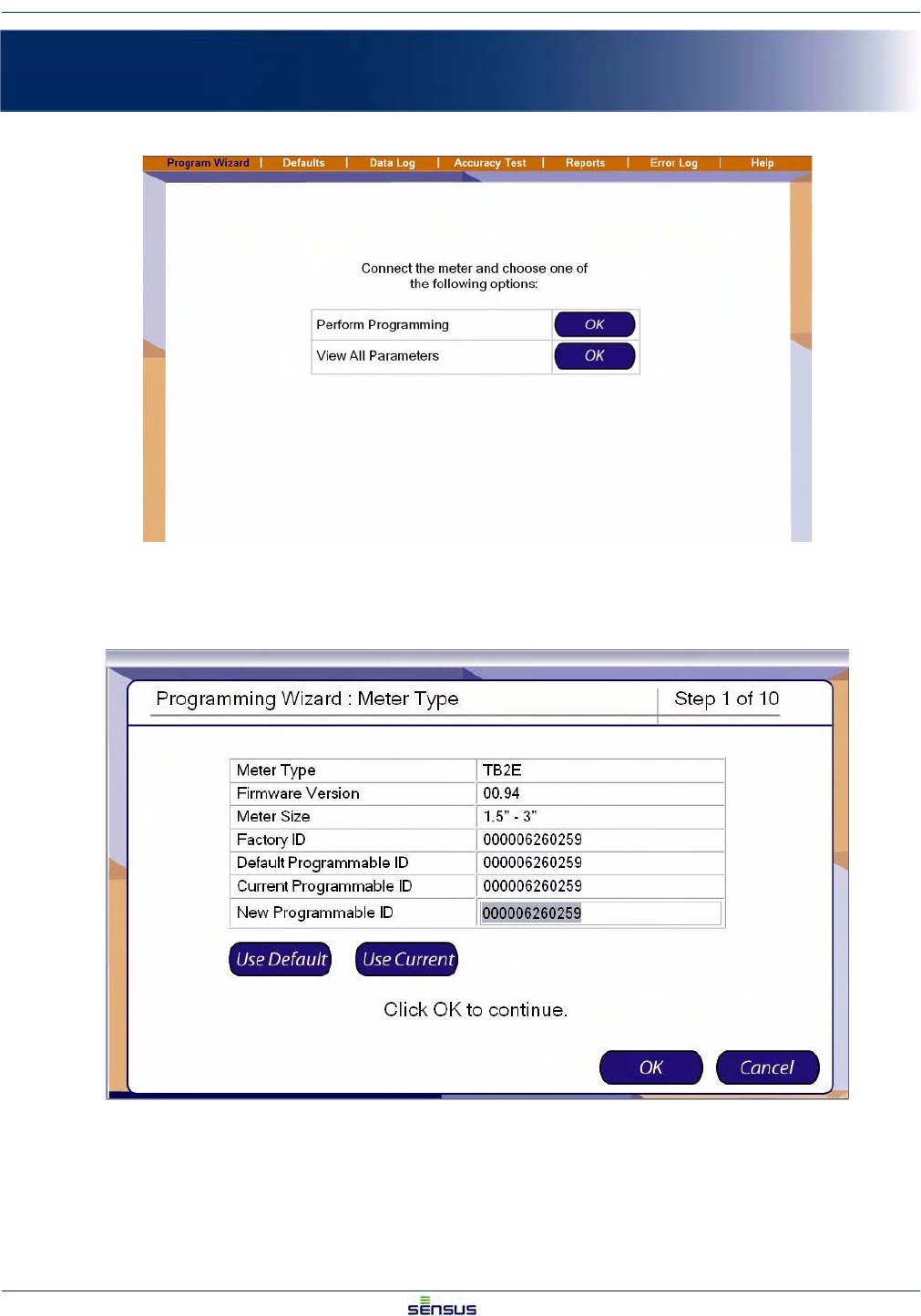
1. From the Program Wizard screen, click the OK button to the right of Perform Programming.
The system displays the Programming Wizard: Meter Type screen.
The Programmable ID identifies the particular meter to the data retrieval system.
2. Select from three options:
• Click the Use Default button to select the Default Programmable ID.
Programming an OMNI T2/C2/F2 Register 3-2
UniPro/OMNI Communicator Model 100A WRMTM-40000
• Click the Use Current button to select the Current Programmable ID.
• Type in a new ID in the New Programmable ID field.
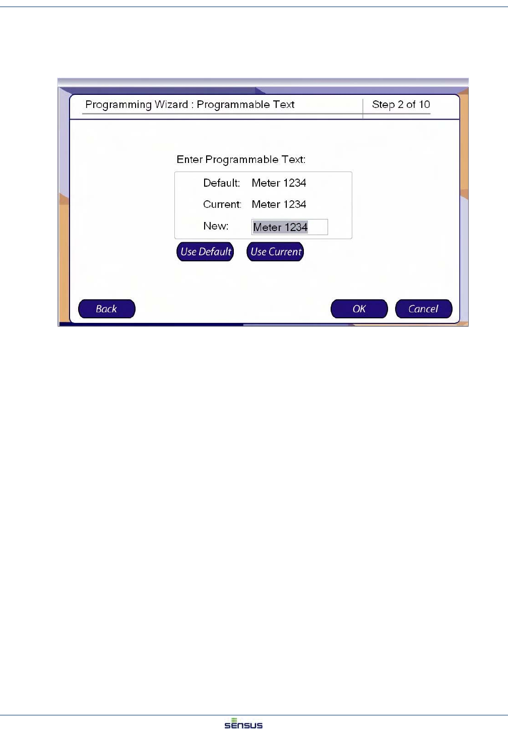
3. Click the OK button to display the Programmable Text screen.
Programmable Text is used in the data retrieval system as XXXXXXXXXXXXXXXXX.
4. Select from three options:
• Click the Use Default button to select the Default Programmable Text.
• Click the Use Current button to select the Current Programmable Text.
• Type in new text in the New field.
5. Click:
•Back to return to the Programmable ID screen.
•Cancel to stop programming and return to the Program Wizard screen.
•OK to accept the Programmable Text and display the Reading Digits screen.
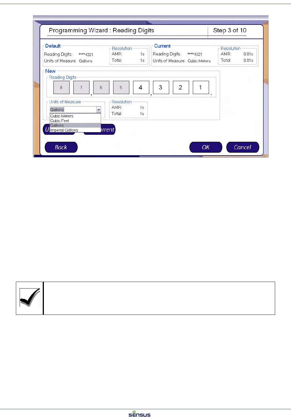
Programming an OMNI T2/C2/F2 Register 3-3
UniPro/OMNI Communicator Model 100A WRMTM-40000
The Reading Digits screen allows you to set the number of digits that are displayed on the register and the units of
measure for the reading.
The window lists the Default settings and the Current settings; the Resolution sections automatically calculate the
resulting AMR and Total display resolutions for the settings.
6. Select from three options:
• Click the Use Default button to select the Default Reading Digits.
• Click the Use Current button to select the Current Reading Digits.
• Select a New set of reading digits by clicking the first and last digits of the range you
wish to display. For example to display the least significant four digits click the 4 box,
then the 2 box. The selected digits will display a white background and the unselected
digits will display a gray background.
7. Select a Units of Measure from the drop-down list.
8. Click:
• Back to return to the Programmable Text screen.
• Cancel to stop programming and return to the Program Wizard screen.
• OK to accept the Reading Digits and display the Reading Mode screen.
If you do not make one of the above selections, the system will automatically use the
Default settings.
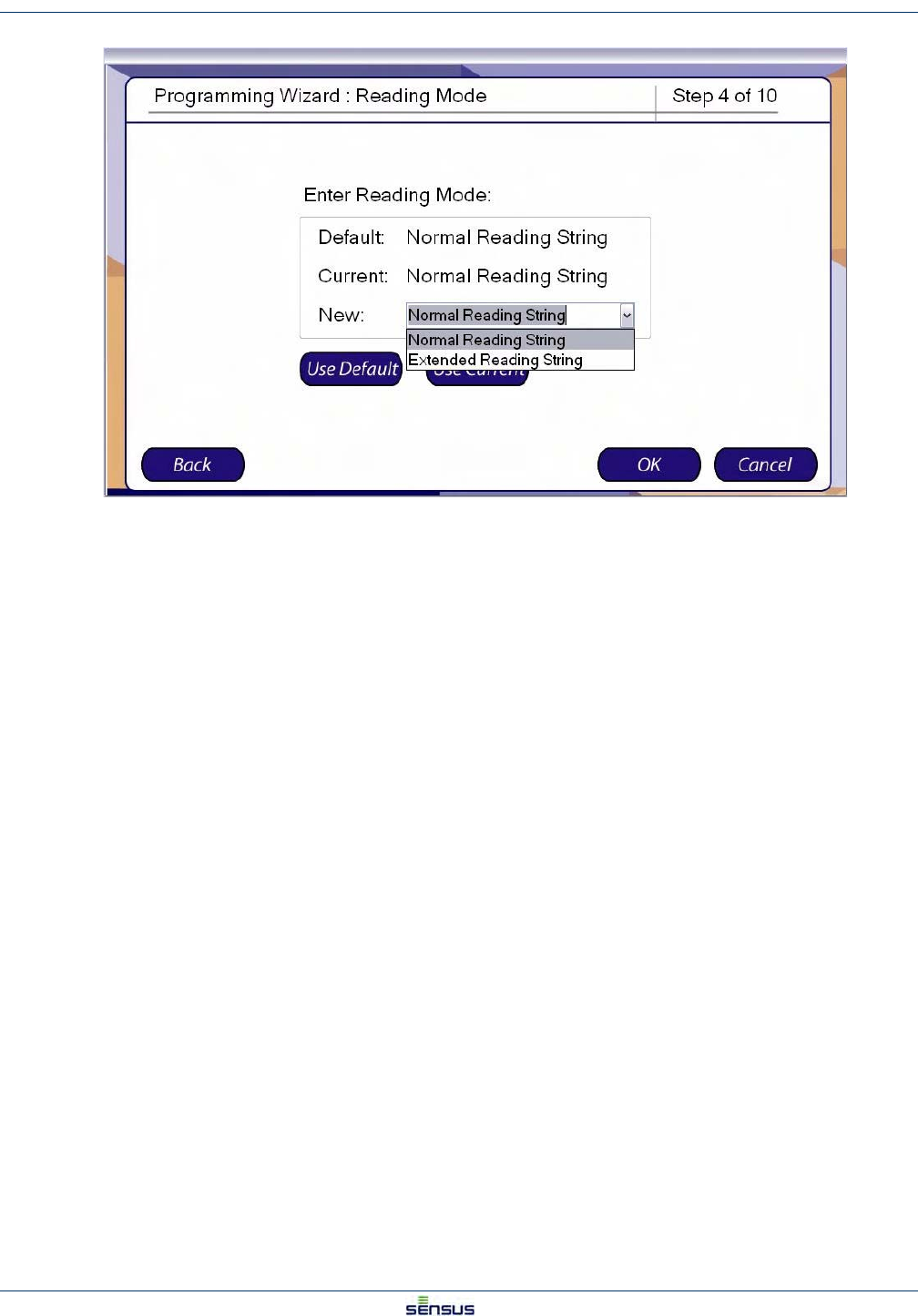
Programming an OMNI T2/C2/F2 Register 3-4
UniPro/OMNI Communicator Model 100A WRMTM-40000
With a Normal Reading String, the data stream from the register contains the meter reading and the Meter ID only.
With an Extended Reading string, the data stream includes information such as the manufacturer fields and meter/
register specific data.
9. Select from three options:
• Click the Use Default button to select the Default Reading Mode.
• Click the Use Current button to select the Current Reading Mode.
• Use the drop-down list in the New field to select either the Normal or Extend Reading
String.
10. Click:
•Back to return to the Reading Digits screen.
•Cancel to stop programming and return to the Program Wizard screen.
•OK to accept the Reading String and display the Pulse Output screen.
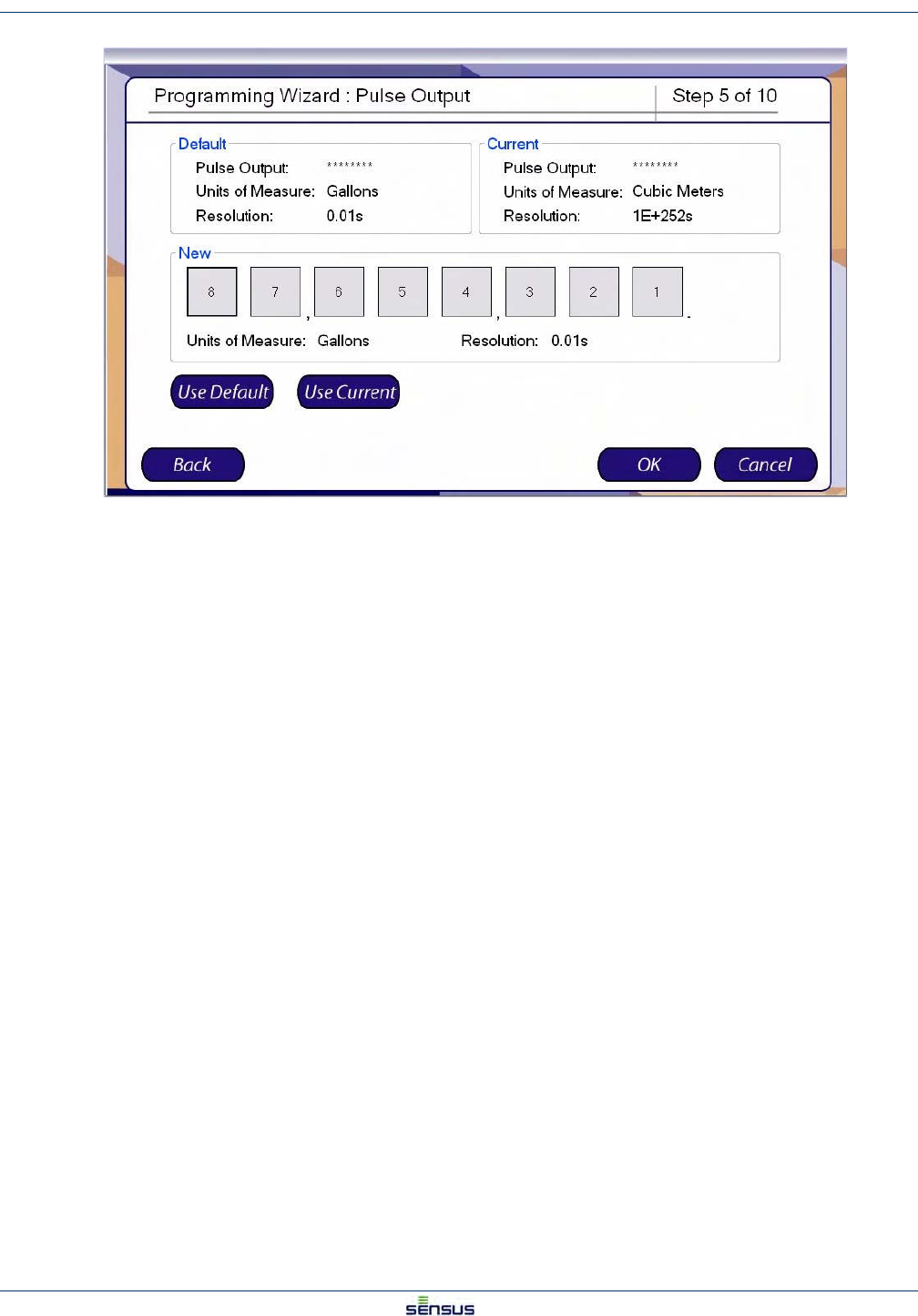
Programming an OMNI T2/C2/F2 Register 3-5
UniPro/OMNI Communicator Model 100A WRMTM-40000
The Pulse Output determines the decimal place that a pulse represents in the pulse output. The screen displays
the Default and Current settings with the Units of Measure and Resolution for each.
11. Select from three options:
• Click the Use Default button to select the Default Pulse Output.
• Click the Use Current button to select the Current Pulse Output.
• Select a New Pulse Output by clicking on the decimal place that you want a pulse to
represent.
12. Click:
•Back to return to the Reading Mode screen.
•Cancel to stop programming and return to the Program Wizard screen.
•OK to accept the Pulse Output and display the Display Mode screen.
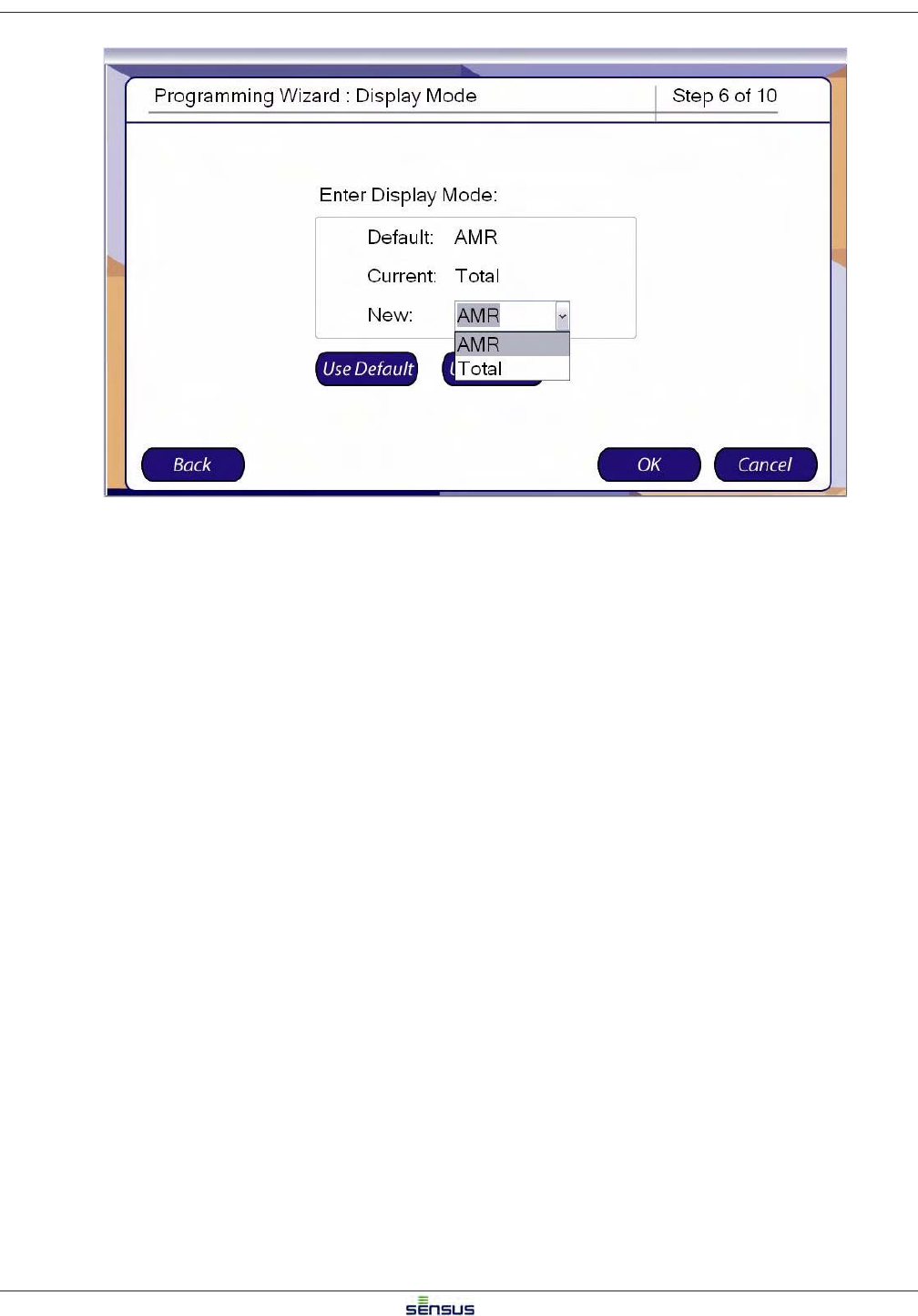
Programming an OMNI T2/C2/F2 Register 3-6
UniPro/OMNI Communicator Model 100A WRMTM-40000
The Display Mode screen determines whether the display will show the Total or AMR output. The Total display will
always show the full eight digits of the reading. The AMR output will display the output of the AMR register,
selected in the Reading Digits screen.
13. Select from three options:
• Click the Use Default button to select the Default Display Mode.
• Click the Use Current button to select the Current Display Mode.
• Use the drop-down list in the New field to select either the Total or AMR Display Mode.
14. Click:
• Back to return to the Pulse Output screen.
• Cancel to stop programming and return to the Program Wizard screen.
• OK to accept the Display Mode and display the Summary screen.
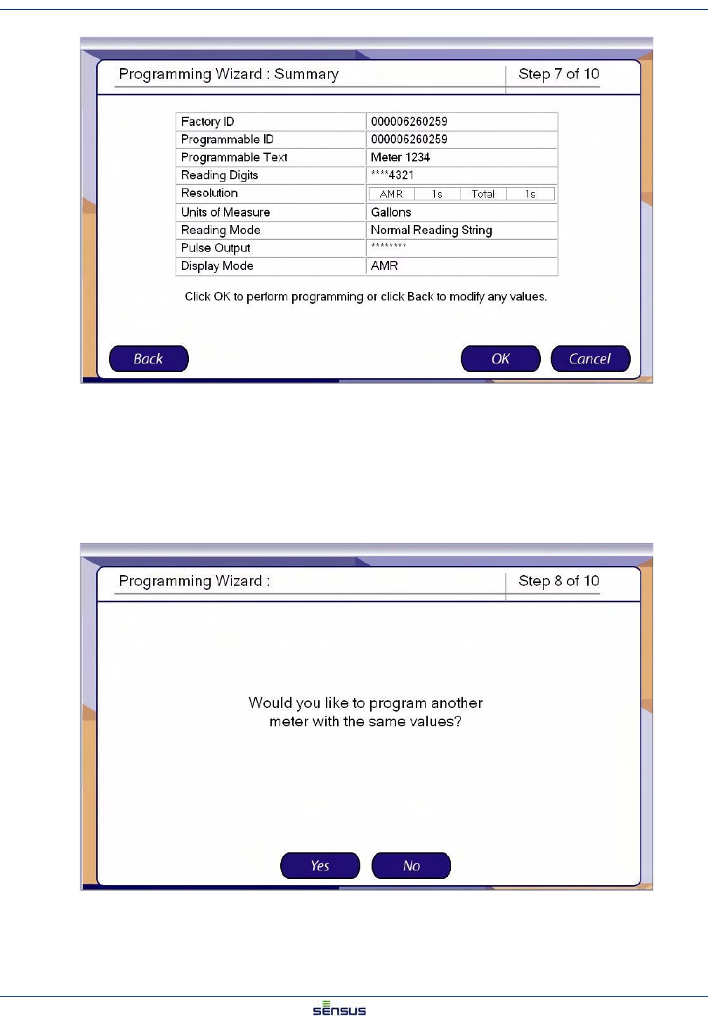
Programming an OMNI T2/C2/F2 Register 3-7
UniPro/OMNI Communicator Model 100A WRMTM-40000
The Summary screen shows the selections made in Steps 2 to 13.
15. Click:
•Back to return to the Display Mode screen.
•Cancel to stop programming and return to the Program Wizard screen.
•OK to accept the data as shown and program the register.
If you accept the data in Step 14, the system displays the Additional Meter Programming screen.
16. Click:
•Yes to program another meter with the same settings.
Programming an OMNI T2/C2/F2 Register 3-8
UniPro/OMNI Communicator Model 100A WRMTM-40000
•No to discontinue programming and go the end screen (skip to Step 17).
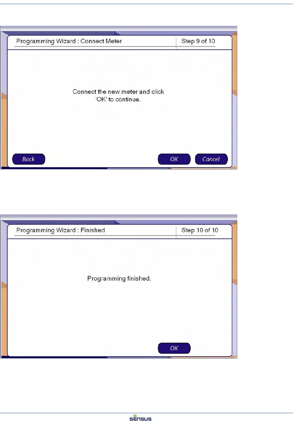
17. Click:
•Back to return to the Additional Meter Programming screen.
•Cancel to stop programming and return to the Program Wizard screen.
•OK to program another meter with the same settings.
The Finished screen indicates that the register programming is complete.
18. Click OK to acknowledge the screen and return to the Program Wizard screen.
Setting Meter Defaults 4-2
UniPro/OMNI Communicator Model 100A WRMTM-40000
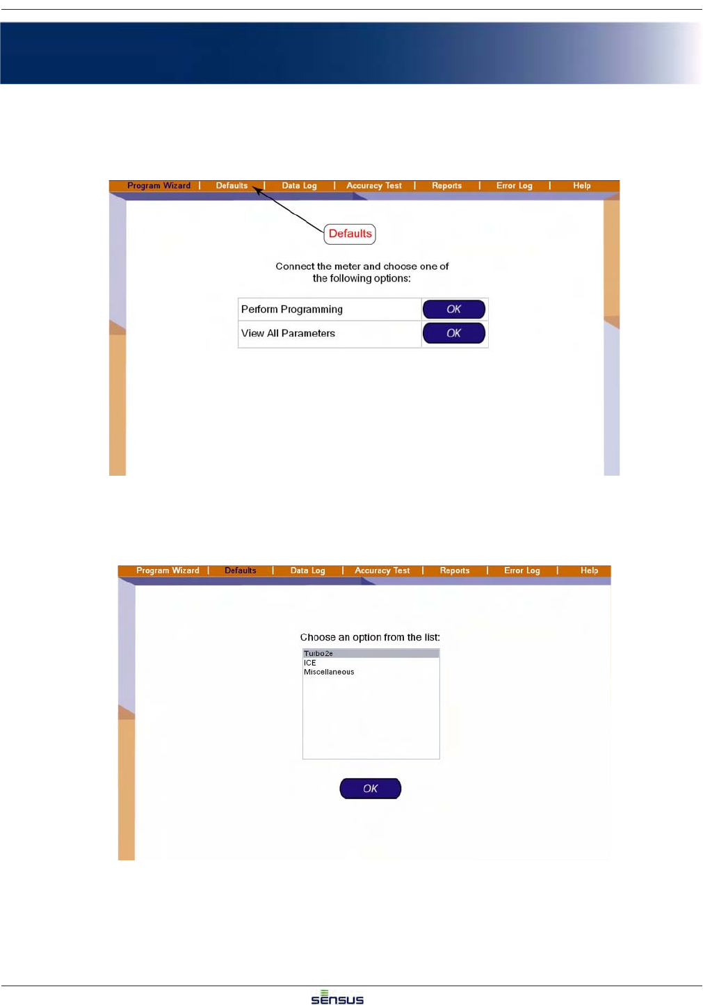
4.2 Setting Turbo2e/OMNI Defaults
From the Defaults screen:
1. Click Turbo2e in the option list, then click OK.
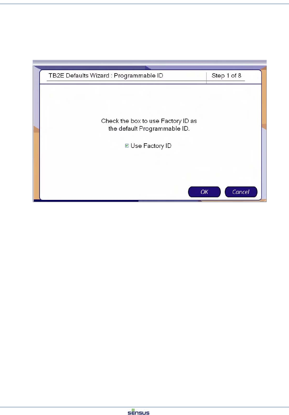
The system displays the Programmable ID screen.
2. Check the box to use the Factory ID as the default Programmable ID.
Uncheck the box to enter your own Programmable ID.
3. Click:
•Cancel to stop programming and return to the Default Options screen.
•OK to display the Programmable Text default screen.
Setting Meter Defaults 4-3
UniPro/OMNI Communicator Model 100A WRMTM-40000
.
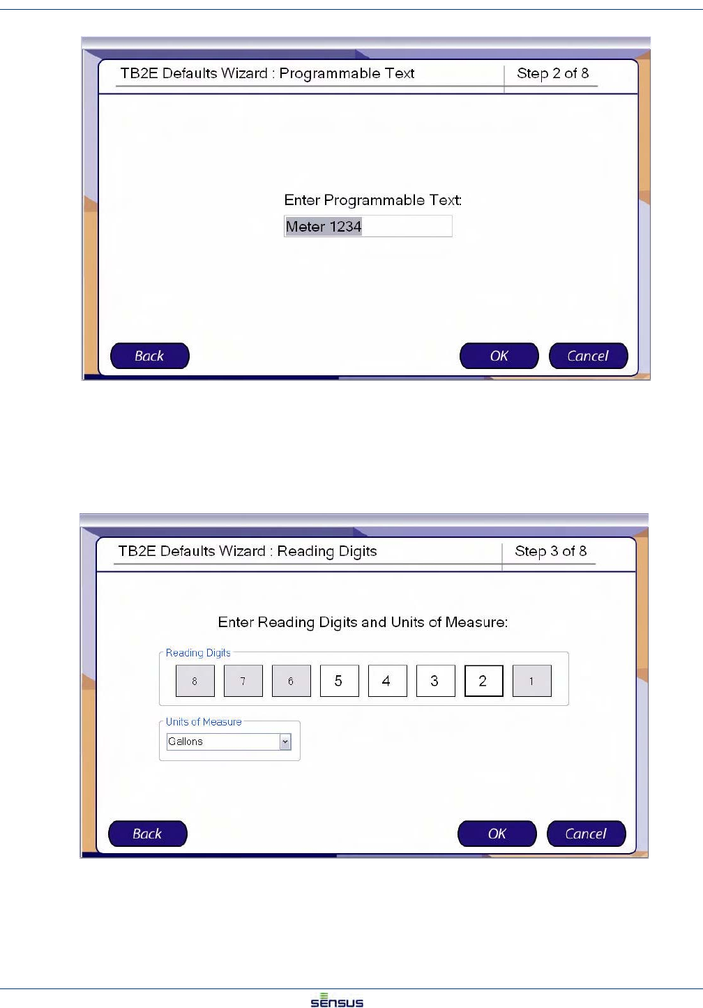
4. Enter the text you wish to serve as the default Programmable Text.
5. Click:
•Back to return to the Programmable ID screen.
•Cancel to stop programming and return to the Default Options screen.
•OK to display the Reading Digits default screen.
The Reading Digits sets the number of digits that are displayed on the register and the units of measure for the
reading.
Setting Meter Defaults 4-4
UniPro/OMNI Communicator Model 100A WRMTM-40000
6. Select a default set of reading digits by clicking the first and last digits of the range you wish to
display. For example, to display the least significant four digits, click the 4 box then the 2 box. The
selected digits will display a white background and the unselected digits will display a gray
background.
7. Select the Units of Measure from the drop-down list.
8. Click:
•Back to return to the Programmable Text screen.
•Cancel to stop programming and return to the Default Options screen.
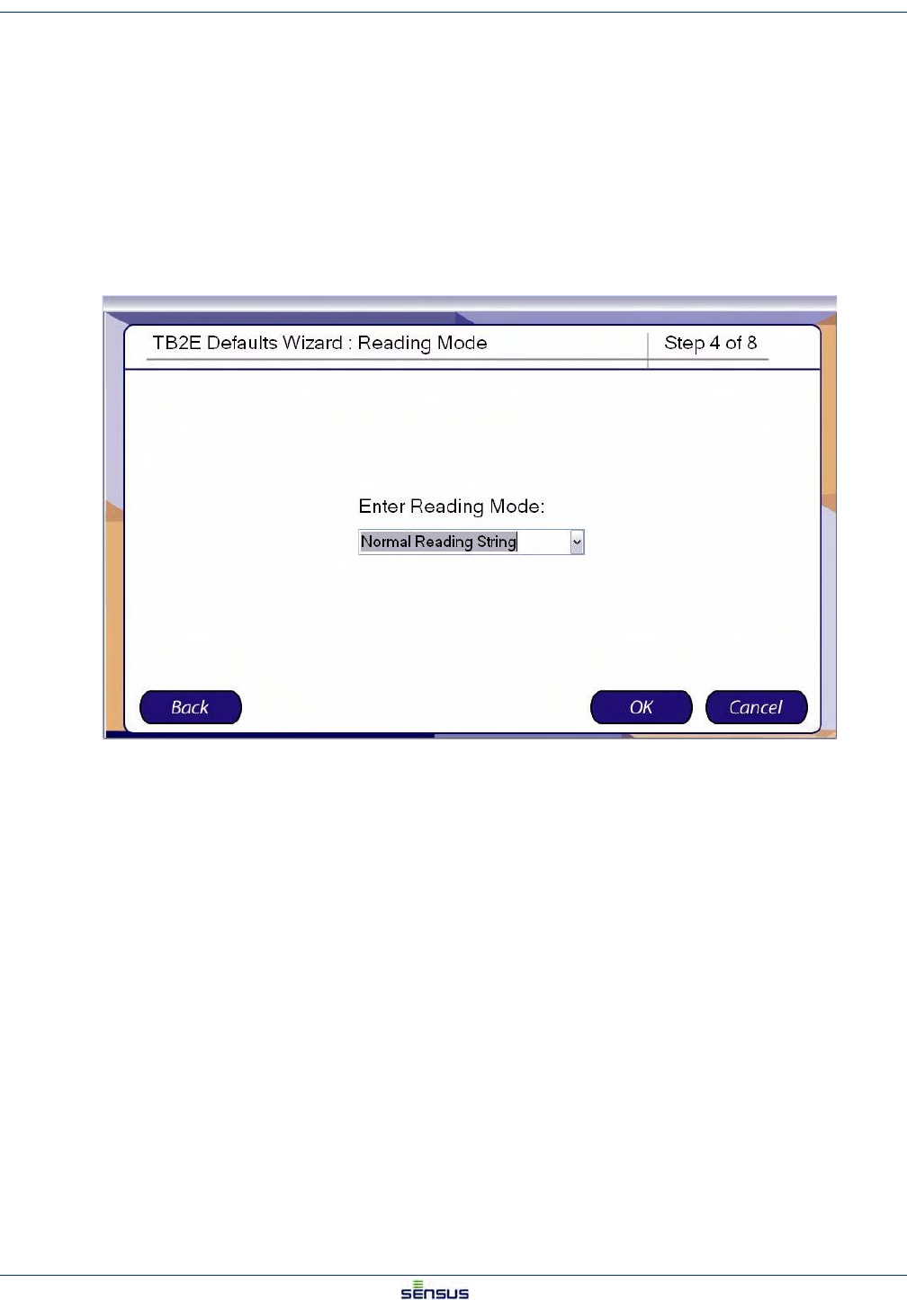
•OK to display the Reading Mode default screen.
9. From the drop-down list, select Normal or Extended Reading String as the default Reading Mode.
10. Click:
•Back to return to the Reading Digits screen.
•Cancel to stop programming and return to the Default Options screen.
•OK to display the Pulse Output default screen.
Setting Meter Defaults 4-5
UniPro/OMNI Communicator Model 100A WRMTM-40000
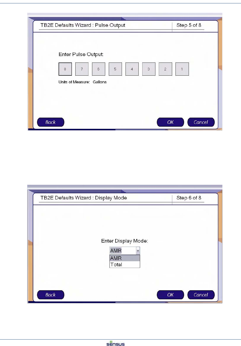
The Pulse Output determines the decimal place that a pulse represents in the pulse output.
11. Select the decimal place for the default Pulse Output.
12. Click:
•Back to return to the Reading Mode screen.
•Cancel to stop programming and return to the Default Options screen.
•OK to display the Display Mode default screen.
Setting Meter Defaults 4-6
UniPro/OMNI Communicator Model 100A WRMTM-40000
The Display Mode determines whether the display will show the Total or AMR output. The Total display will
always show the full eight digits of the reading. The AMR output will display the output of the AMR register,
selected in the Reading Digits screen.
13. From the drop-down list, select AMR or Total as the default Display Mode.
14. Click:
•Back to return to the Pulse Output screen.
•Cancel to stop programming and return to the Default Options screen.
•OK to display the Summary screen.
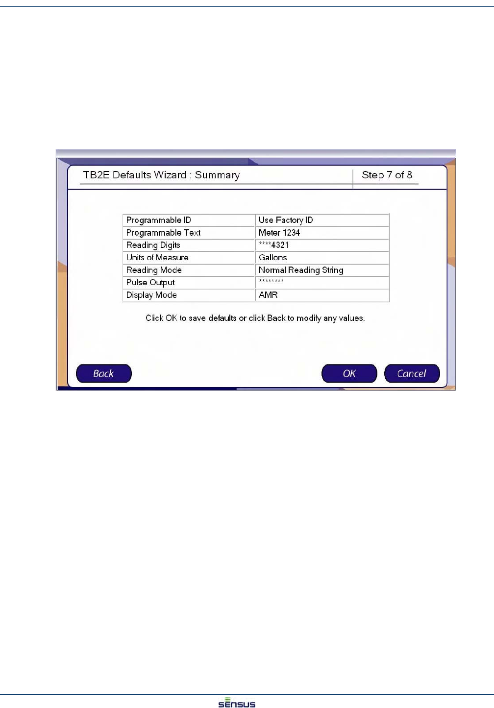
15. Click:
•Back to return to the Display Mode screen.
•Cancel to reject all defaults and return to the Default Options screen.
•OK to accept the data as shown and save the defaults.
If click OK in Step 14, the system displays the Defaults Finished screen.
Setting Meter Defaults 4-7
UniPro/OMNI Communicator Model 100A WRMTM-40000
16. Click OK to return to the Default Options screen.
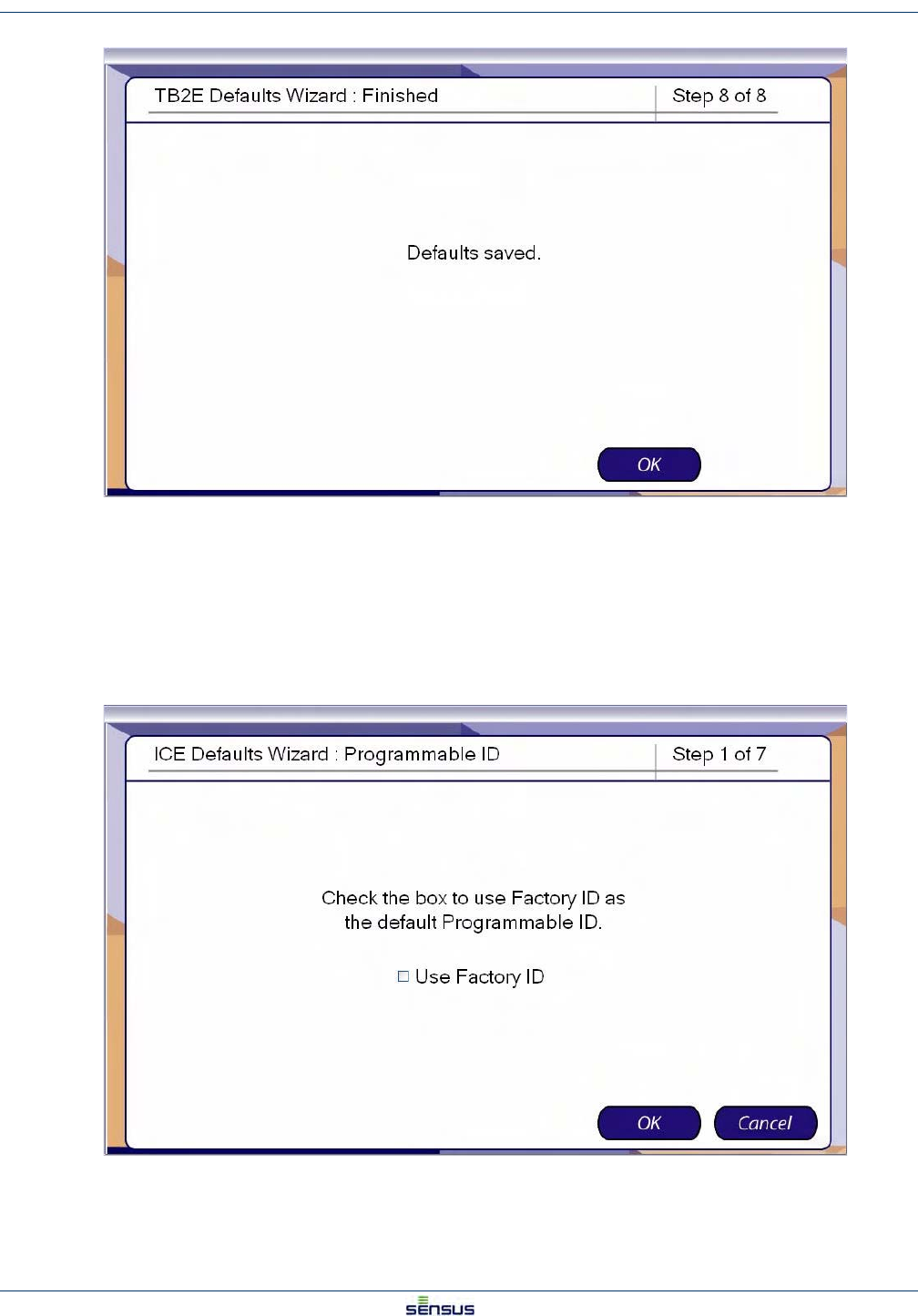
4.3 Setting ICE Defaults
From the Defaults screen:
1. Click ICE in the option list, then click OK.
The system displays the Programmable ID screen.
2. Check the box to use the Factory ID as the default Programmable ID.
Uncheck the box to enter your own Programmable ID.
Setting Meter Defaults 4-8
UniPro/OMNI Communicator Model 100A WRMTM-40000
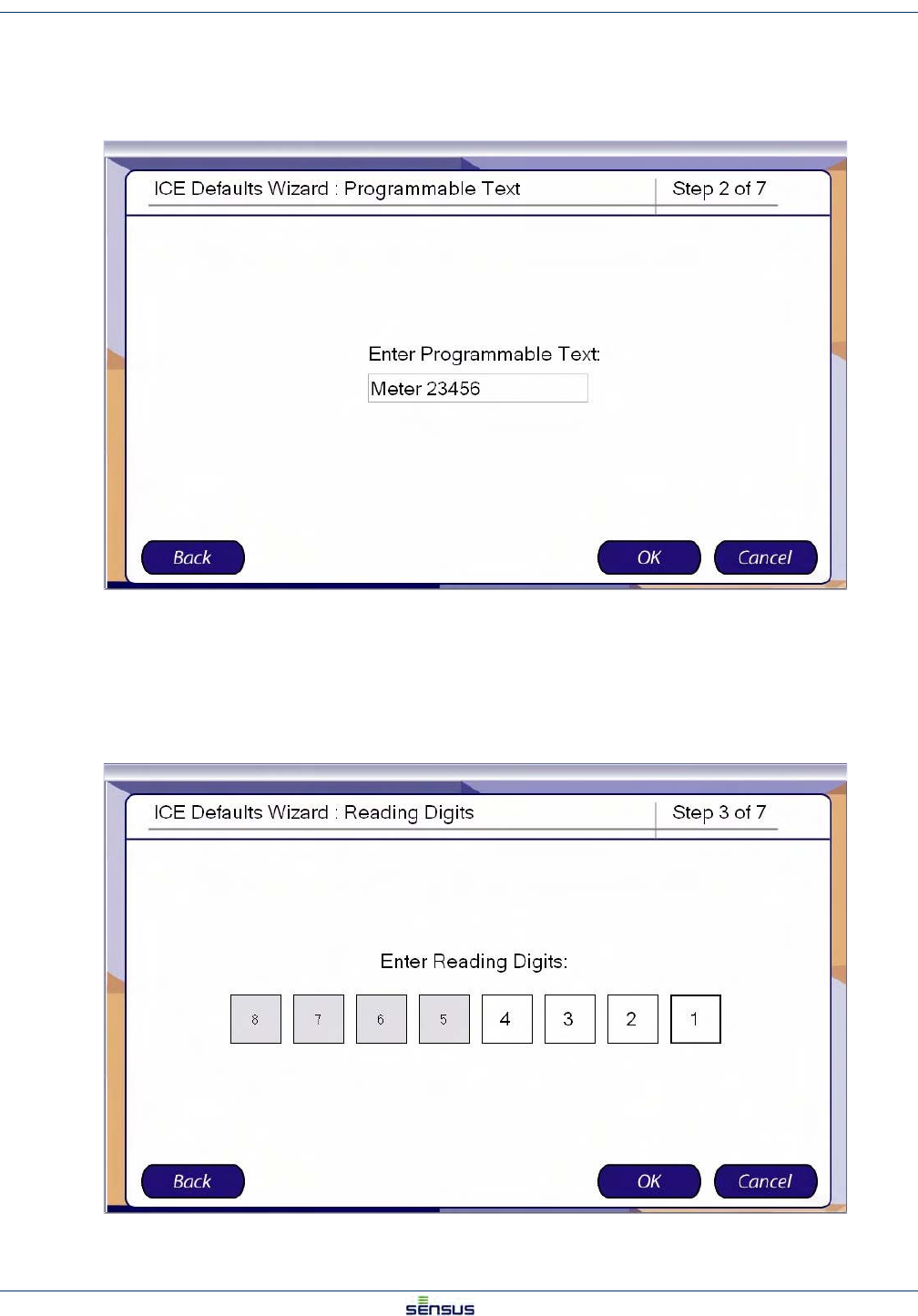
3. Click:
•Cancel to stop programming and return to the Default Options screen.
•OK to display the Programmable Text default screen.
4. Enter the text you wish to serve as the default Programmable Text.
5. Click:
•Back to return to the Programmable ID screen.
•Cancel to stop programming and return to the Default Options screen.
•OK to display the Reading Digits default screen.
Setting Meter Defaults 4-9
UniPro/OMNI Communicator Model 100A WRMTM-40000
The Reading Digits sets the number of digits that are displayed on the register and the units of measure for the
reading.
6. Select a default set of reading digits by clicking the first and last digits of the range you wish to
display. For example, to display the least significant four digits, click the 4 box then the 2 box. The
selected digits will display a white background and the unselected digits will display a gray
background.
7. Click:
•Back to return to the Programmable Text screen.
•Cancel to stop programming and return to the Default Options screen.
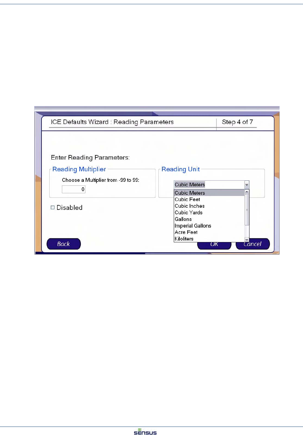
•OK to display the Reading Parameters default screen.
8. In the Reading Multiplier box, enter a default multiplier from -99 to 99.
9. In the Reading Unit drop-down, select a default unit.
10. Click:
•Back to return to the Reading Digits screen.
•Cancel to stop programming and return to the Default Options screen.
•OK to display the Reading Mode default screen.
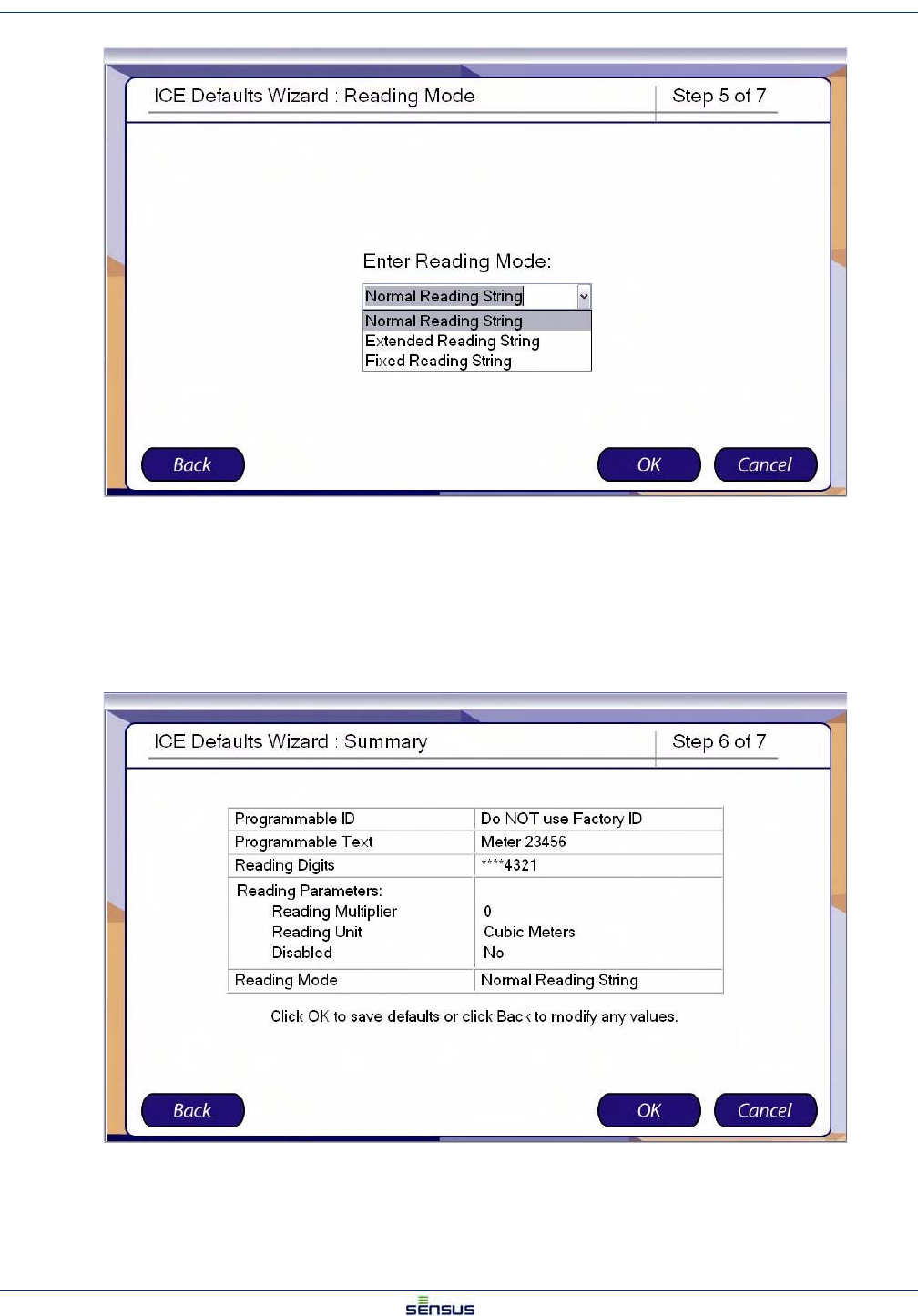
Setting Meter Defaults 4-10
UniPro/OMNI Communicator Model 100A WRMTM-40000
11. From the drop-down list, select Normal, Extended, or Fixed Reading String as the default Reading
Mode.
12. Click:
•Back to return to the Reading Parameters screen.
•Cancel to stop programming and return to the Default Options screen.
•OK to display the Summary screen.
13. Click:
•Back to return to the Reading Mode screen.
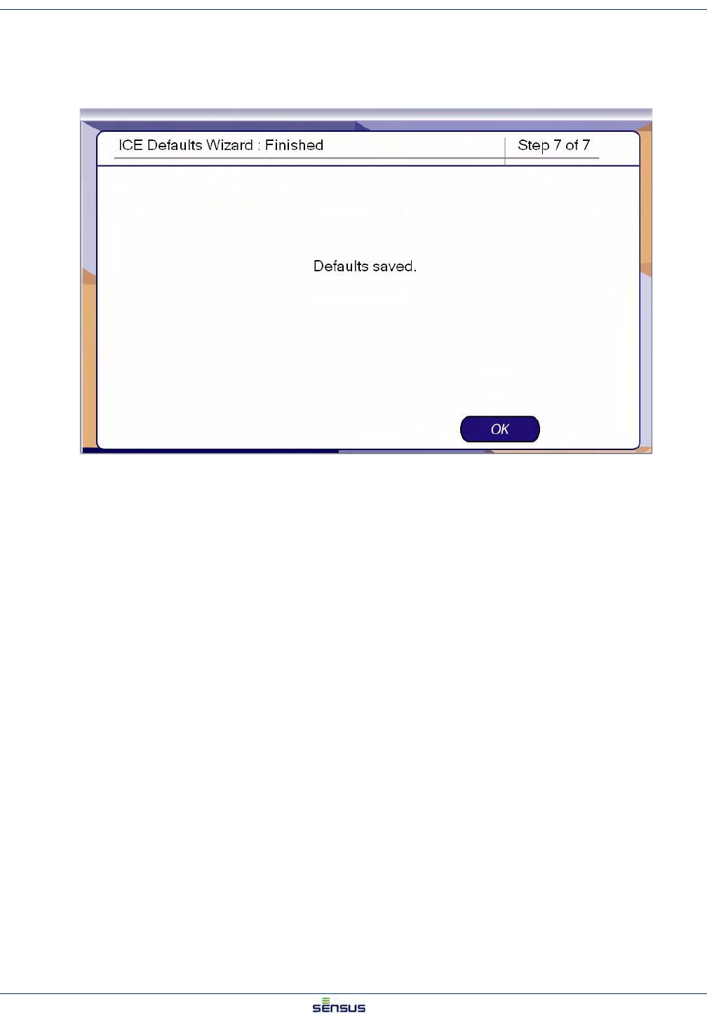
Setting Meter Defaults 4-11
UniPro/OMNI Communicator Model 100A WRMTM-40000
•Cancel to reject all defaults and return to the Default Options screen.
•OK to accept the data as shown, save the defaults.
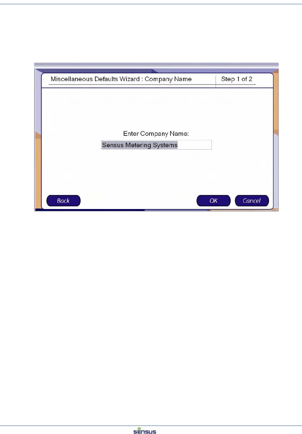
If click OK in Step 13, the system displays the Defaults Finished screen.
14. Click OK to return to the Default Options screen.
Setting Meter Defaults 4-12
UniPro/OMNI Communicator Model 100A WRMTM-40000
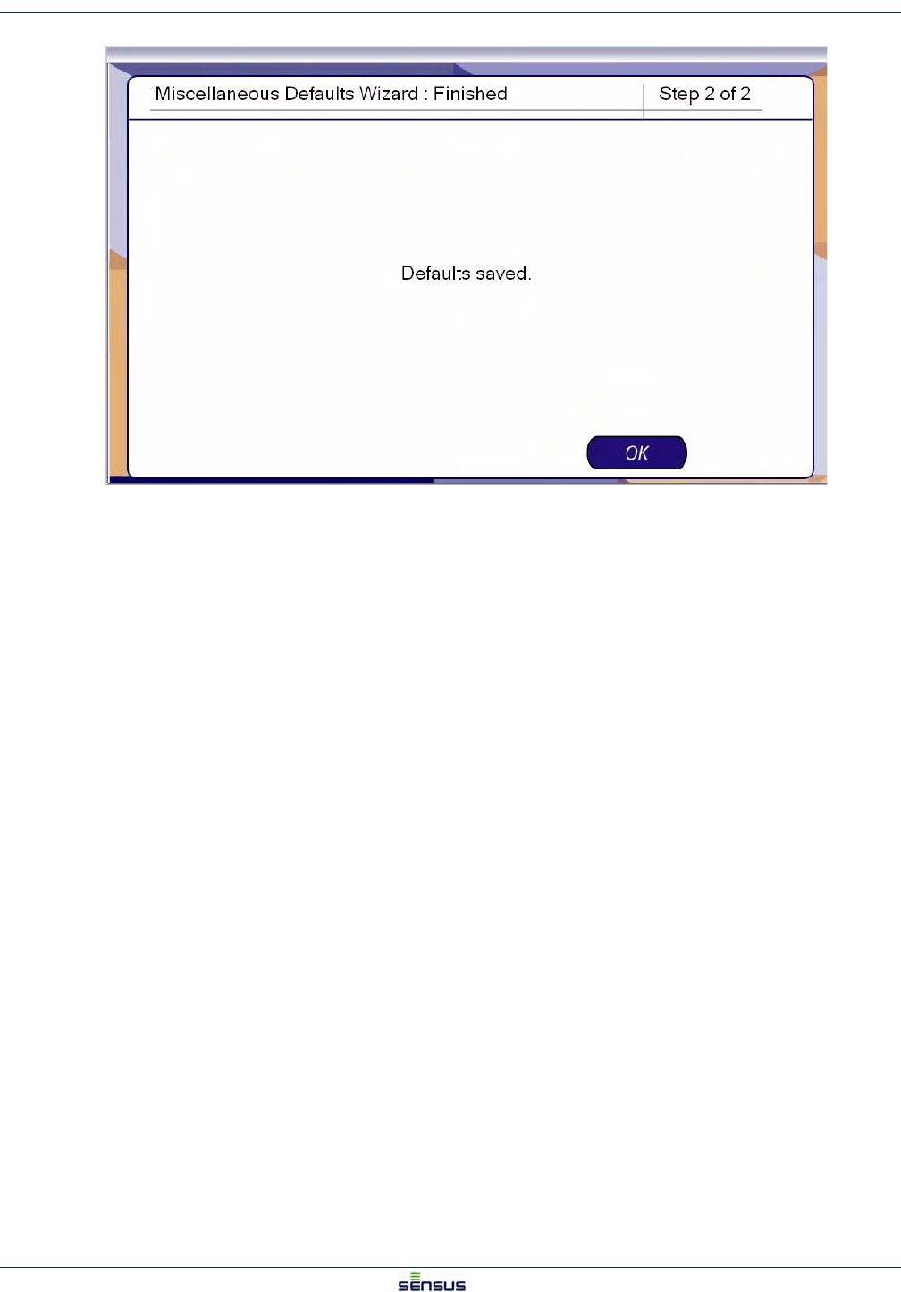
4.4 Setting Miscellaneous Defaults
From the Defaults screen:
1. Click Miscellaneous in the option list, then click OK.
The system displays the Programmable ID screen.
2. Enter your company name in the Company Name box.
3. Click:
•Back to return to the Default Options screen.
•Cancel to stop programming and return to the Default Options screen.
•OK to display the Finished screen.
Data Log 5-1
UniPro/OMNI Communicator Model 100A WRMTM-40000
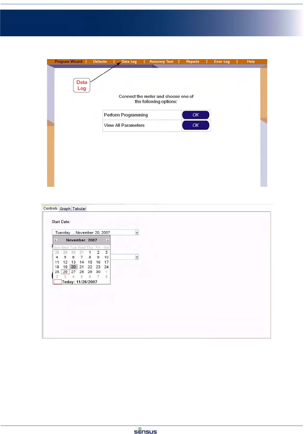
5 Data Log
1. Open UniPro or navigate to the Program Wizard screen:
2. Select Data Log in the command bar to open the Data Log Controls screen:
3. Use the drop down list calendars to select a Start Date and End Date for the data read from the
register.
The register retains up to 30 days of data. The default dates are the current date for the End Date
and 30 days before the end date for the Start Date. The software will only accept a start date if it
contains data. If the register contains less than 30 days, a popup window will appear to suggest the
start date.
Data Log 5-2
UniPro/OMNI Communicator Model 100A WRMTM-40000
4. Click the Read Meter button.
The Data Transfer Progress bar shows the data transfer progress.
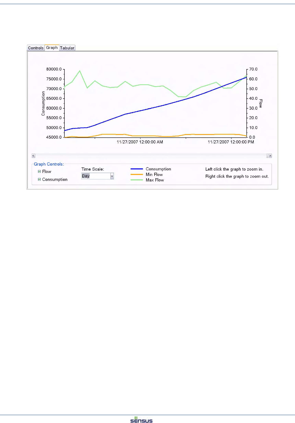
5. When the data transfer bar clears, select the Graph tab to view the data graph.
The graph charts Consumption, Minimum Flow, and Maximum Flow for the period defined in Step 3. The default
time scale is Month. You can zoom in to a time scale of Week or Day by left-clicking on the graph or by selecting
from the Time Scale drop down list. You can zoom out the time scale by right-clicking on the graph.
You can also click on Flow or Consumption on the left of the Graph Controls to view or not view the respective
graph data.
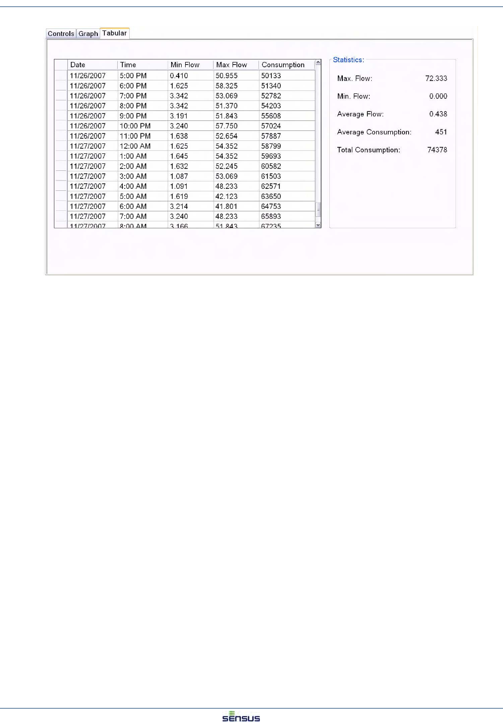
6. Click the Tabular tab to view the data in table form.
Data Log 5-3
UniPro/OMNI Communicator Model 100A WRMTM-40000
The Tabular view lists the Date, Time, Minimum Flow, Maximum Flow, and Consumption by hour for the period
defined in Step 3. The Statistics box to the right of the table lists the Maximum Flow, Minimum Flow, and Total
Consumption, and calculates the Average Flow and Average Consumption for the period.
Reports 6-1
UniPro/OMNI Communicator Model 100A WRMTM-40000
6 Reports
Three report types are available: Meter Programming, Data Logging, and Accuracy Testing. You can view the
reports on your screen and you can print them.
6.1 Opening a Report
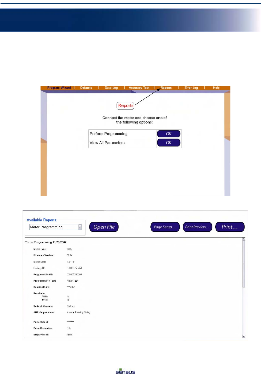
1. Click Reports in the command bar.
The system shows the Reports screen.
Reports 6-2
UniPro/OMNI Communicator Model 100A WRMTM-40000
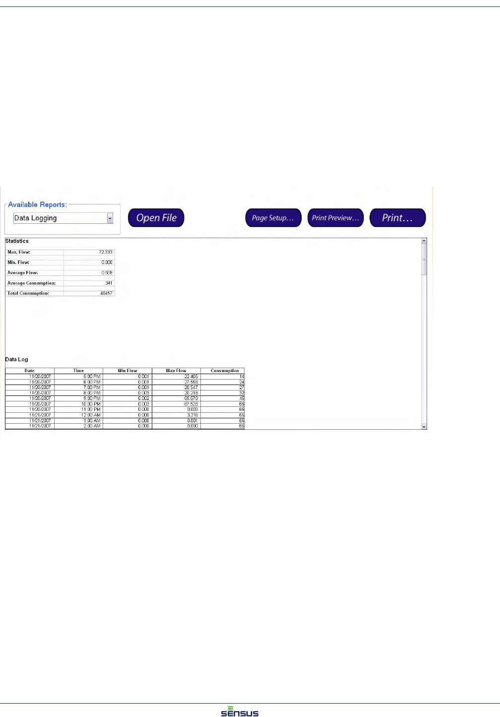
2. In the Available Reports section, select the type of report you want from the drop down list.
3. Click the Open File button.
A standard Windows Open dialog box opens.
4. Select the appropriate register type, ICE or Turbo and click the Open button.
The window presents the directory of stored reports. The reports are listed by the Programmable ID
and the date and time that the report was stored. For example, a data log listed as
06230138_2007112680834 opens a report for meter ID 06230138 stored on 11/26/2007 at
8:08:34 a.m.
5. Select the date of the report you wish to view and click the Open button.
The screen shows the report you selected.
The following illustration shows a typical Data Log report.
6. Use the scroll bars to view the remainder of the Data Log.
6.2 Printing a Report
To print the report you are viewing:
1. Click the Page Setup… button to review the default printer’s page settings, such as orientation,
margins, etc.
2. Click the Print Preview… button to review the appearance of the report.
3. Click the Print… button to open the Print dialog for your default printer.

Error Log 7-1
UniPro/OMNI Communicator Model 100A WRMTM-40000
7Error Log
The Error Log displays UniPro operational errors and faults, and Omni register error codes.
7.1 Viewing and Acknowledging Errors
To view the Error Log screen, select Error Log in the command bar.
The top section of the Error Log screen displays the operational errors that have occurred. These include
ErrorIDShortDescriptionLongDescriptionCategory
1Exception occurredA fatal error has occurred. Please contact 2
factory or service personnel.
2License Expiration WarningThe license is about to expire. Please obtain a 1
new license file.
3Communication TimeoutFailed to connect or communicate with the meter.1
4License ErrorInvalid license. Please obtain a new license file.2
5A non-fatal error has occurredA non-fatal error has occurred1
6There is no data to retrieve from the data log.There is no data to retrieve from the data log.1
7The connected meter does not support the Data The connected meter does not support the Data 1
Log featureLog feature.
8The connected meter does not support this The connected meter does not support this 1
feature.feature.

Index
UniPro/OMNI Communicator Model 100A WRMTM-40000
Index
A
acknowledging errors 7-1
available reports 6-2
C
COM port
assignment 2-1
setting 2-1
command bar 1-1
company name
miscellaneous default 4-12
D
data log 5-1
graph tab 5-2
reading meter 5-2
report 6-2
selecting dates 5-1
tabular tab 5-3
dates, selecting data log 5-1
default options 4-1
defaults
company name 4-12
ICE programmable text 4-8
ICE reading digits 4-9
ICE reading mode 4-10
ICE reading parameters 4-9
ICE summary 4-10
miscellaneous 4-7, 4-12
Turbo2e/OMNI 4-2
Turbo2e/OMNI display mode 4-6
Turbo2e/OMNI programmable ID 4-2
Turbo2e/OMNI programmable text 4-3
Turbo2e/OMNI pulse output 4-5
Turbo2e/OMNI reading digits 4-3
Turbo2e/OMNI reading mode 4-4
Turbo2e/OMNI summary 4-6
Device Manager 2-1
display mode 3-6
Turbo2e/OMNI default 4-6
E
error log 7-1
acknowledging 7-1
viewing 7-1
exit 1-1
G
graph tab 5-2
H
hardware
attaching 2-1
help screen 2-1
I
ICE defaults 4-7
programmable text 4-8
reading digits 4-9
reading mode 4-10
reading parameters 4-9
summary 4-10
L
layout, screen 1-1
M
meter defaults
setting 4-1
meter status 1-1
meter type 3-1
meter, reading 5-2
miscellaneous defaults 4-12
company name 4-12
O
options screen, defaults 4-1
overview 1-1
P
printing reports 6-2
program area 1-1
programmable ID
Turbo2e/OMNI default 4-2
programmable text 3-2
ICE default 4-8
Turbo2e/OMNI default 4-3
programming
display mode 3-6
meter type 3-1
programmable text 3-2
pulse output 3-5
reading digits 3-3
reading mode 3-4
summary 3-7
progress bar 1-1
pulse output 3-5
Turbo2e/OMNI default 4-5

Index
UniPro/OMNI Communicator Model 100A WRMTM-40000
R
reading digits 3-3
ICE default 4-9
Turbo2e/OMNI default 4-3
reading mode 3-4
ICE default 4-10
Turbo2e/OMNI default 4-4
reading parameters
ICE default 4-9
reports
available types 6-2
data log 6-2
opening 6-1
printing 6-2
S
screen layout 1-1
command bar 1-1
exit 1-1
meter status 1-1
program area 1-1
progress bar 1-1
setting COM port 2-1
setting ICE defaults 4-7
setting meter defaults 4-1
setting miscellaneous defaults 4-12
setting Turbo2e/OMNI defaults 4-2
setup, hardware 2-1
software overview 1-1
summary 3-7
ICE default 4-10
Turbo2e/OMNI defaults 4-6
T
T2/C2/F2 register
default options 4-1
display mode 3-6
meter defaults 4-1
meter type 3-1
programmable text 3-2
programming 3-1
pulse output 3-5
reading digits 3-3
reading mode 3-4
summary 3-7
Turbo2e/OMNI defaults 4-2
tabsdata log, graph 5-2
data log, tabular 5-3
tabular tab 5-3
Turbo2e/OMNI defaults 4-2
display mode 4-6
programmable ID 4-2
programmable text 4-3
pulse output 4-5
reading digits 4-3
reading mode 4-4
summary 4-6
U
USB port 2-1
V
viewing error log 7-1