Sensus Metering Systems GFL GAS METER DATA TRANSMITTER User Manual USERS MANUAL
Sensus Metering Systems Inc. GAS METER DATA TRANSMITTER USERS MANUAL
USERS MANUAL

5015 B.U. Bowman Drive Buford, GA 30518 USA Voice: 770-831-8048 Fax: 770-831-8598
Transmitter Certification
Test Report
FCC ID: SDBGFL
FCC Rule Part: CFR 47 Part 24 Subpart D, Part 90 Subpart I, Part 101
Subpart C
ACS Report Number: 06-0194-LD
Applicant: Advanced Metering Data Systems, LLC
Equipment Type: Water Meter Data Transmitter
Trade Name: Sensus AMDS GFL Gas Meter Transmitter
Model(s): GFL
Users Manual
1
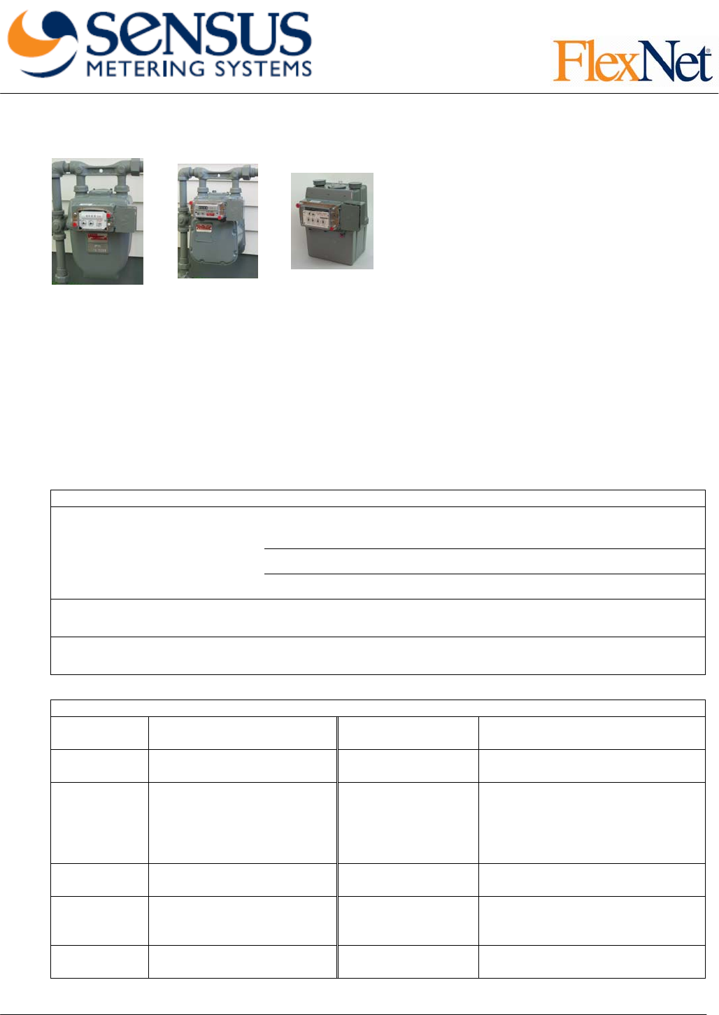
Product Description
The FlexNet® wireless transmitter for gas AMR
applications permits offsite meter reading by way of a
fixed base radio network. In addition to solving meter
reading problems such as lockouts, entering unsafe
meter locations, "curbside" reading estimates,
estimated billing, and errors associated with manual
meter reading methods, a fixed network provides
benefits such as daily reads and status alerts.
A significant advantage of the module is its powerful one- Watt transmitter. The long range enabled by the
strong signal and high receiver sensitivity, minimizes the number of base station receivers and provides
optimal coverage at minimal deployment and ongoing costs. FlexNet transmitters are powered by a
replaceable Lithium battery pack, with an expected service life of over 20 years.
The transmitter is enclosed in a durable polycarbonate casing with a clear cover that enables reusing the
original meter index. The module consists of a narrow band transmitter, magnetic sensors, and mechanical
meter interface that includes a shaft with a magnet. A handheld terminal is used to initialize operation. The
module monitors the meter and sends data to the base station receiver network at predefined and
programmable intervals. Transmitter messages contain meter reading data, status and relevant parameters
such as index pressure and the number of dials. Messages are routed to a database, where the data gets
formatted for export to billing, marketing and customer service systems.
Compatible Meters
R175, R200, RT200, RT230, R275, RT275, R315, R250, R310, S110,
S200, 175S, S120, T120, T110 (11-tooth gear)
R415, RT100, RT360 (18-tooth gear)
Sensus (Rockwell, Equimeter,
Invensys)
MR-8, MR-12 (16-tooth gear)
American/Canadian Meter W75AL, AL175, AC175, AT175, ALC175, AT210, AL225, 5B, AL250,
AR250, AC250, AT250, AM250, AL310, AL350, AT350, AL425, AC630
Actaris (Sprague, Schlumberger) 175, 175WC, 210, 240, 250, 250WC, METRIS 250, 400, 400A
(All slant interface, 3 hole index cover)
Specifications
RF Output 30dBm (1 Watt) Power Supply Lithium Thionyl Chloride batteries
with HLC
Range Urban area (typical) – over
5 miles (8 km) Battery Life
(Typical) Over 20 years for daily reads
Over 10 years for hourly reads
Modulation Proprietary narrow band Regulatory
Compliance
FCC CFR 47 Part 15, Part 24,
Part 90, and Part 101 Rules
Certified Intrinsic Safety
Certification Measurement
Canada Certification
Data Rate Up to 8 Kbps Environmental -40C to +80C, up to 95% relative
humidity
Frequencies 896-960 MHz, 10,240
channels x 6.25 kHz steps Alerts Magnetic tamper Non-reads,
High/Low alerts – via MDM
software
Memory Non-volatile Warranty 20 years for battery (with daily
reads) and electronics
2
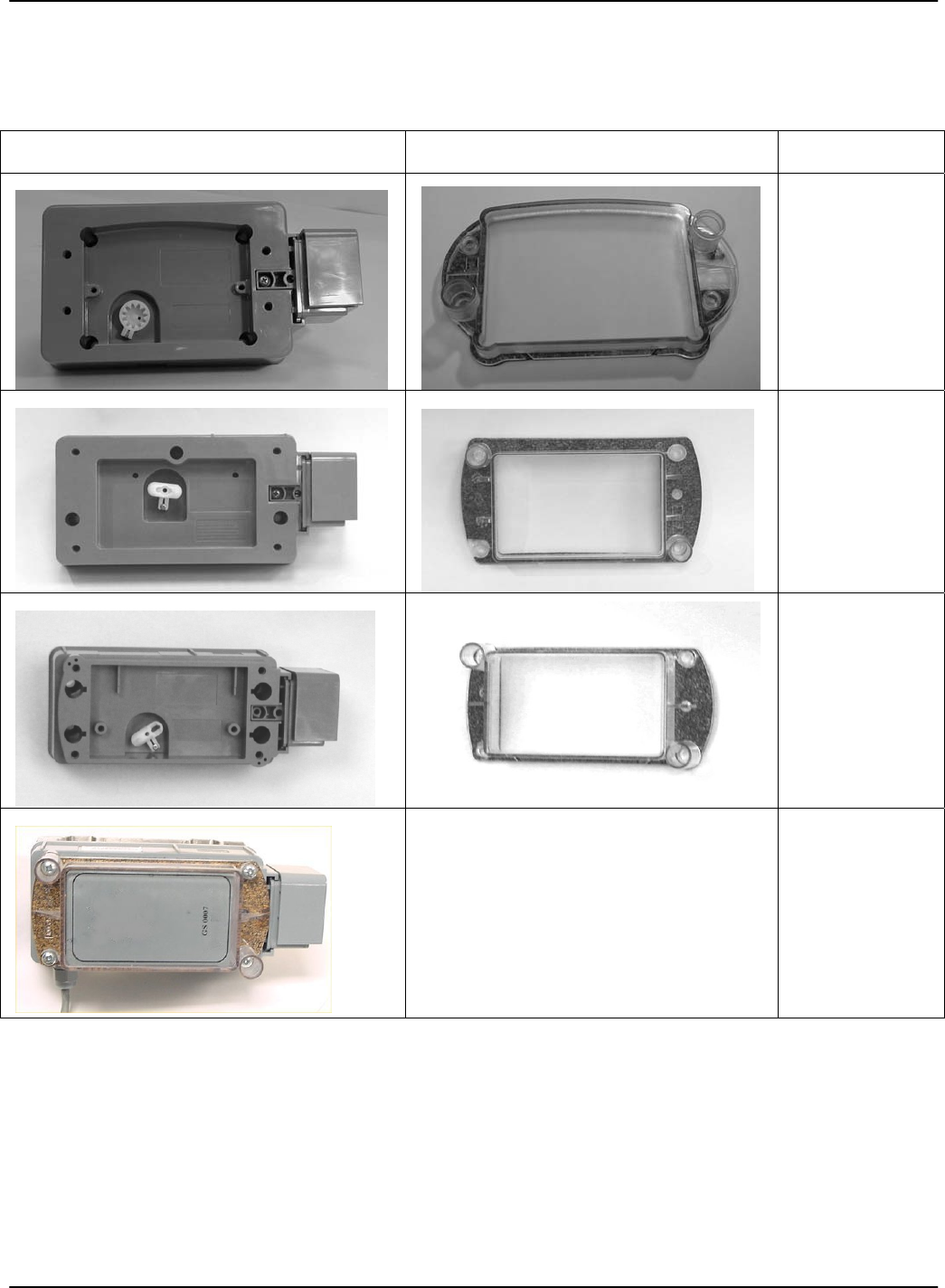
Automated Meter Reading (AMR)
Meter Components
Transmitter Cover
Supported
Meters
FlexNet 100G-FL
AC250, AL175,
AL250, AL5B
(=AL225),
AL425 and any
other American
Meter model
with a standard
residential
index.
FlexNet 200G-FL
S175, S240,
S250,
Schlumberger
Metris MET250
and S400, with
slant index
interface.
FlexNet 300G-FL
AC250, AL175,
AL250, AL5B
(=AL225),
AL425 and any
other American
Meter model
with a standard
residential
index.
FlexNet 700G-FL
Transmitter (on the left) is shown with
cover and mounting plate Sensus Sonix
12, 16, 25,
volume
correcting
instruments and
any other
device with
Form-A or ‘dry
contact’ pulse
output.

3
Transmitter Mounting Instructions
FlexNet 100G-FL, 200G-FL and 300G-FL
See the appendix for descriptions of the screw kits and tools required for mounting the AMR transmitters.
Remove Index Cover
1. Use a small, flat screwdriver to punch out the snap seals covering the index cover screws.
NOTE:
If two (2) or more screws shear off during the cover removal (or were previously sheared off), the meter will need to be replaced by
a qualified utility representative. Reinstall any index cover screws that were removed and cap with seals if possible. Enter the
appropriate information in the Mint HHT
2. Remove the index cover screws.
3. Remove the index cover.
Remove Index
1. Remove the screws securing the index to the meter.
2. Carefully, remove the index from the meter.
3. Remove any debris from the index.
4. Inspect the index for proper operation by turning the input shaft and verifying that the gears turn freely.
5. Inspect the index for any missing or broken hands.
6. Use a putty knife to scrape away any remaining gasket material.
Mount Transmitter
1. Align the transmitter’s shaft with the gas meter’s male/female wriggler.
2. Place the AMR Transmitter on the gas meter.
3. Adjust the transmitter shaft’s position
4. Ensure the shafts are aligned by holding the transmitter in place and gently rotating the transmitter’s
shaft with your other hand.
5. Loosely attach the transmitter to the meter using the transmitter mounting screws
6. Check shaft alignment.
NOTE:
If two (2) or more screws shear off during the cover installation, the meter will need to be replaced by a qualified utility
representative. Reinstall any index cover screws that were removed and cap with seals if possible. Notify the utility of the
condition of the meter in accordance with your company policy.
7. Tighten the transmitter mounting screws.
Replace Index and Install New Index Cover
1. Loosely attach the index to the transmitter using the index screws.
2. Align the index’s male/female wriggler with the transmitter’s shaft, and adjust as needed.
3. Center the index in the transmitter, and ensure there is no binding between the shaft and the wriggler.
4. Secure the index screws.
5. Install the new index cover.
6. Align the gasket with the transmitter.
4
Use care when working with a power screwdriver to insert screws in the plastic Transmitter box. Over
tightening will damage the box and/or weaken the contact. Failure to comply with this caution can result in
damage to the equipment.
7. Secure the cover to the transmitter with the index cover screws.
8. Align and insert the two snap seals into the index cover using a ¼” nut driver until the snap seals are
fully seated.
FlexNet 700G-FL
Pulse Output Identification
1. If the output is a ‘dry contact’ pulse (i.e., magnetic relay, reed switch), use both wires.
2. If the output is an electronic pulse:
a. Connect the ‘plus’ wire, to the red wire from the transmitter.
b. Connect the ‘minus’ or ground wire to the black wire from the transmitter.
Mount Back Plate
NOTE:
When locating a place for the transmitter, consider:
• The wire lengths
• The convenience of wiring and ability to properly secure the wires
• That a high spot is preferable for optimal radio coverage
• The proximity (<6”) of the transmitter to metallic objects (not including the pipe on which
the transmitter is mounted)
1. Locate an appropriate spot for mounting the transmitter.
2. Secure the back plate to the wall with the mounting screws, or to the pipe using the pipe clamp. The
pipe clamp can be horizontal or vertical as long as the back plate is horizontal.
Mount Transmitter
1. Before mounting the transmitter, use the HHT to ensure that the transmitter is functioning properly.
Refer to the Gas AMR Installation HHT (Mint) User’s Guide.
2. Secure the transmitter to the back plate using the mounting screws.
3. Ensure that the transmitter is completely secure and horizontal.
Splice Wires
1. Strip the wires so that approximately 2" of the wires are exposed.
2. Insert two matching wire ends, as identified in Step 2 of “Pulse Output Identification,” into a
UY-2 gel-cap.
3. Crimp the gel-cap using the 3M Scotchlok® E-9Y steppe-jaw crimping tool until the cap releases the
waterproof gel,
4. Ensure the splice is secure by gently pulling on the gel-cap while holding the wires.
5. Repeat Step 1 through Step 4 for the remaining connection.
6. Secure any unused connections with UY-2 gel-caps.
If any of the wire connections are not being used they should be capped at the end with a UY-2 gel-cap.
This is to prevent water from getting into unused wires.
7. Secure excess or loose wiring.
8. Mount index cover on transmitter and secure with the index cover screws.
9. Align and insert the two snap seals into the index cover using a ¼” nut driver until the snap seals are
fully seated.
5
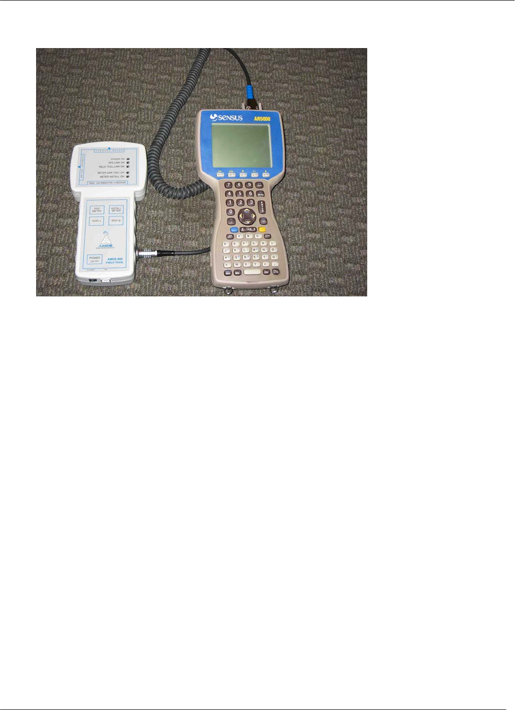
Initialize Transmitter
Use a Sensus handheld terminal (HHT) to initialize the transmitter.
7
Appendix: Screw Kits and Tools
Screw Kits
Screw kits accompany the AMR transmitters. Each kit contains any of the following (depending on
transmitter model):
• Mounting screws
• Index screws
• Index cover screws
• Snap seals
• 3M Scotchlok® UY-2 butt connector “gel-caps”
• Pipe clamp
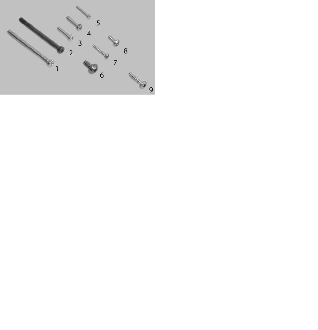
Mounting Screws
1. Equimeter/Rockwell commercial meter (e.g. R750) – 5/16” x 3½” combo fillister
2. American commercial meter (e.g. AL800) – #18-18 x 84 Phillips pan head
3. American residential meter (e.g. AC250) – ¼” x 1” Phillips fillister
4. Schlumberger/Sprague residential meter (e.g. S175) – 10-24 x 1” Phillips fillister
5. Equimeter/Rockwell residential meter (e.g. R275) – 10-24 x 1” Phillips fillister
Index Screws
6. Equimeter/Rockwell commercial meter (e.g. R750) – WN1411 KA 60x14 Phillips
7. Equimeter/Rockwell residential meter (e.g. R275) – WN1412 KA 35x22 Phillips
8. American & Schlumberger/Sprague residential meter– WN1411 KA 40x12 Phillips
Index Cover Screws
9. All residential meters – WN1412 KA 50x20 Phillips
Tools
Mounting the transmitters require the use of standard and specialized tools. Depending on the model of the
transmitter, the following tools are needed.
• Phillips screwdriver (#1, #2)
• Standard screwdriver (¼” blade, 5/32” blade)
• Stiff-blade putty knife
• Pointed tweezers
• ¼” Nut driver
• 3M Scotchlok® E-9Y steppe-jaw crimping tool with wire cutter
• Sensus handheld terminal (HHT)

8
APPENDIX A: REGULATORY INFORMATION:
COMPLIANCE INFORMATION:
FCC:
NOTE: This equipment has been tested and found to comply with the limits for a Class B digital
device, pursuant to Part 15 of the FCC rules. These limits are designed to provide reasonable
protection against harmful interference in a residential installation. This equipment generates,
uses, and can radiate radio frequency energy and, if not installed and used in accordance with
the instructions, may cause harmful interference to radio communications. However, there is no
guarantee that interference will not occur in a particular installation. If this equipment does cause
harmful interference to radio or television reception, which can be determined by turning the
equipment off and on, the user is encouraged to try to correct the interference by one or more of
the following measures:
• Reorient of relocate the receiving antenna.
• Increase the separation between the equipment and receiver.
• Connect the equipment into an outlet or circuit different from that to which the receiver is
connected.
• Consult the dealer or an experienced radio/TV technician for help.
WARNING: Changes or modifications to this device not expressly approved by
Sensus or AMDS LLC could void the user’s authority to operate this equipment.
Industry Canada:
This Class B digital apparatus meets all requirements of the Canadian Interference Causing
Equipment Regulations. Operation is subject to the following two conditions: (1) this device may
not cause harmful interference, and
(2) this device must accept any interference received, including interference that may cause
undesired operation.
Cet appareillage numérique de la classe B répond à toutes les exigences de
l'interférence canadienne causant des règlements d'équipement. L'opération est
sujette aux deux conditions suivantes: (1) ce dispositif peut ne pas causer
l'interférence nocive, et (2) ce dispositif doit accepter n'importe quelle
interférence reçue, y compris l'interférence qui peut causer l'opération peu
désirée.
RF Exposure:
In accordance with FCC requirements of human exposure to radiofrequency fields, the radiating
element shall be installed such that a minimum separation distance of 20cm is maintained.

9
APPENDIX B: REGULATORY LABELING
FCC LABELING:
This device when used in an end product where the FCC label of the device is not visible must have an exterior
label as shown below.
Contains FCC ID: SDBGFL
Contains IC: 2220A-GFL
This device complies with Part 15 of the FCC Rules and Industry
Canada requirements. Operation is subject to the following two
condition: (1) This device may not cause harmful interference, and
(2) this device must accept any interference received, including
interference that may cause undesired operation.”
This Class B digital apparatus complies with Canadian ICES-003.
Cet appareil numérique de la classe B est conforme à la norme NMB-
003 du Canada.