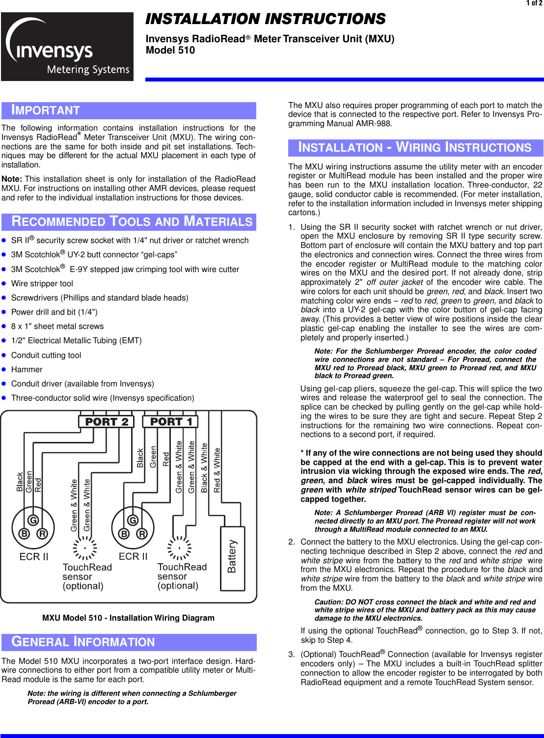
Sensus Metering Systems MXU510 Radio Transceiver For Meter Reading System User Manual

Sensus Metering Systems Radio Transceiver For Meter Reading System

User Manual

 The following information contains installation instructions for theInvensys RadioRead ா  Meter Transceiver Unit (MXU). The wiring con-nections are the same for both inside and pit set installations. Tech-niques may be different for the actual MXU placement in each type ofinstallation. Note:  This installation sheet is only for installation of the RadioReadMXU. For instructions on installing other AMR devices, please requestand refer to the individual installation instructions for those devices. ● SR II ®  security screw socket with 1/4" nut driver or ratchet wrench ● 3M Scotchlok ®  UY-2 butt connector “gel-caps” ● 3M Scotchlok ®   E-9Y stepped jaw crimping tool with wire cutter ● Wire stripper tool ● Screwdrivers (Phillips and standard blade heads) ● Power drill and bit (1/4") ● 8 x 1" sheet metal screws ● 1/2" Electrical Metallic Tubing (EMT) ● Conduit cutting tool ● Hammer ● Conduit driver (available from Invensys) ● Three-conductor solid wire (Invensys specification) I MPORTANT R ECOMMENDED  T OOLS   AND  M ATERIALS  1 of 2 MXU Model 510 - Installation Wiring Diagram The MXU also requires proper programming of each port to match thedevice that is connected to the respective port. Refer to Invensys Pro-gramming Manual AMR-988.The MXU wiring instructions assume the utility meter with an encoderregister or MultiRead module has been installed and the proper wirehas been run to the MXU installation location. Three-conductor, 22gauge, solid conductor cable is recommended. (For meter installation,refer to the installation information included in Invensys meter shippingcartons.)1. Using the SR II security socket with ratchet wrench or nut driver,open the MXU enclosure by removing SR II type security screw.Bottom part of enclosure will contain the MXU battery and top partthe electronics and connection wires. Connect the three wires fromthe encoder register or MultiRead module to the matching colorwires on the MXU and the desired port. If not already done, stripapproximately 2"  off outer jacket  of the encoder wire cable. Thewire colors for each unit should be  green ,  red , and  black . Insert twomatching color wire ends –  red  to  red ,  green  to  green , and  black  to black  into a UY-2 gel-cap with the color button of gel-cap facingaway. (This provides a better view of wire positions inside the clearplastic gel-cap enabling the installer to see the wires are com-pletely and properly inserted.) Note: For the Schlumberger Proread encoder, the color codedwire connections are not standard – For Proread, connect theMXU red to Proread black, MXU green to Proread red, and MXUblack to Proread green.  Using gel-cap pliers, squeeze the gel-cap. This will splice the twowires and release the waterproof gel to seal the connection. Thesplice can be checked by pulling gently on the gel-cap while hold-ing the wires to be sure they are tight and secure. Repeat Step 2instructions for the remaining two wire connections. Repeat con-nections to a second port, if required. * If any of the wire connections are not being used they shouldbe capped at the end with a gel-cap. This is to prevent waterintrusion via wicking through the exposed wire ends. The  red , green , and  black  wires must be gel-capped individually. The green  with  white striped  TouchRead sensor wires can be gel-capped together. Note: A Schlumberger Proread (ARB VI) register must be con-nected directly to an MXU port. The Proread register will not workthrough a MultiRead module connected to an MXU. 2. Connect the battery to the MXU electronics. Using the gel-cap con-necting technique described in Step 2 above, connect the  red  and white stripe  wire from the battery to the  red  and  white stripe   wirefrom the MXU electronics. Repeat the procedure for the  black  and white stripe  wire from the battery to the  black  and  white stripe  wirefrom the MXU.  Caution: DO NOT cross connect the black and white and red andwhite stripe wires of the MXU and battery pack as this may causedamage to the MXU electronics. If using the optional TouchRead ®  connection, go to Step 3. If not,skip to Step 4. 3. (Optional) TouchRead ®  Connection (available for Invensys registerencoders only) – The MXU includes a built-in TouchRead splitterconnection to allow the encoder register to be interrogated by bothRadioRead equipment and a remote TouchRead System sensor. I NSTALLATION  - W IRING  I NSTRUCTIONS The Model 510 MXU incorporates a two-port interface design. Hard-wire connections to either port from a compatible utility meter or Multi-Read module is the same for each port. Note: the wiring is different when connecting a Schlumberger Proread (ARB-VI) encoder to a port. G ENERAL  I NFORMATION INSTALLATION INSTRUCTIONS Invensys RadioRead ா  Meter Transceiver Unit (MXU)Model 510
  Invensys Metering SystemsP.O. Box 487450 N. Gallatin AvenueUniontown, PA 154011-800-METER-IT1-800-638-3748FAX (Direct to Factory)Local: (724) 439-7729Toll Free: 1-800-888-2403Web site: www.ims.invensys.comselect North American WaterEmail: h2oinfo@ims.invensys.com AUTHORIZED INVENSYS DISTRIBUTOR  2 of 2 Wall Mount TouchPad  – Using two-conductor or three-conductorwire cable and gel-caps, connect wires to each of the  green  and white stripe  wires from the MXU. Note: If three-conductor wire cable is used, the third wire is notutilized for the TouchRead Connection. At the TouchPad connection, connect the same two wires to the terminal screws on the back of the TouchPad. Caution: Be sure there is no bare wire-to-wire contact. (TheTouchRead connection is non-polarity sensitive and will work as longas the same color wires are used at both ends of the connection.If three-conductor wire is used, be sure the third “dead” wire is notmistakenly connected at either end.) Repeat the connections for asecond port if required. Pit-set Mount Sensor  – The TouchRead pit-set sensor includes afactory-sealed three-conductor wire cable. Proper wire connectionsare therefore important. To activate the pit-set TouchRead sensor,use only the  red  and  black  wires from the sensor. Approximately 2"of the cable’s outer jacket must be stripped from its end to accessthese wires. Then, using gel-caps, connect the  black wire  from thesensor to one of the  green and white stripe  wires from the MXU.Next, connect the  red wire  from the sensor to the other  green  and white stripe wire  from the MXU. Repeat the connections for a sec-ond port if required. Note: When connecting a Schlumberger Proread (ARB VI) registerdirectly to an MXU port, the TouchRead splitter feature is not available. 4. Verify MXU operation prior to final assembly: To verify RadioReadreading, use Radio Frequency Solid State Interrogator (RFSSI) orVehicle Transceiver (VXU) to display the register odometer read-ing(s), register ID number(s), and MXU ID number. (For AMR trou-bleshooting, refer to bulletin AMR-309.) -To verify TouchRead reading , use a TouchRead visual readerto display register odometer reading(s) and register ID number(s).If MXU does not function, check all wire connections, re-do theconnections or change battery pack. (For complete TouchReadinstallation and troubleshooting, see installation bulletins: TR-728,TR-997, and TR-998.)5. After wiring connections are completed and MXU operation is veri-fied, align guides of top and bottom parts of MXU and close, bring-ing the connection wire(s) out the front side, using the wire pass-thru guides located on either side of the security screw. Secure thetop and bottom parts of the MXU using the security screw. Caution: DO NOT over-tighten security screw. For Wall Mounting: (Indoors and Outdoors) 1. Using MXU mounting bracket, find a convenient location for theMXU mounting. It is recommended that the MXU be mounted in anupright position so the top part with the Invensys logo is  facing up.The MXU mounting bracket can be mounted to a wall using screwsor fastened to an object using heavy duty wire ties. Grooves havebeen placed in the back of the bracket for mounting on either hori-zontal or vertical (existing) pipes.2. After mounting MXU bracket, snap the MXU (which should alreadybe wired  as noted in the preceding wiring instructions) into thebracket. Be sure the locating tabs on either side of the MXU havesnapped into position in the mounting bracket.The installation isnow complete. MXU M OUNTING  I NSTRUCTIONS 3. TouchPad Mounting (Optional) – If mounting the MXU outdoors anda  TouchRead  TouchPad connection is to be included, mountingholes can be drilled in the side of the MXU bracket. Using shortscrews or plastic rivets, mount the TouchPad to the side of the MXUbracket. Caution: When using screws, be sure they do not penetrate theMXU enclosure when mounting the TouchPad. The TouchPad canalso be mounted in a location away from the MXU. Be sure to usescrews that are designed for and applicable to the mounting surface. For Pit Set Mounting: 1. Use 1/2” EMT. Select a location for the conduit where the MXU’sinstalled position will not interfere with the meter and allow the MXUto be located as high as possible inside the meter box. The MXUshould be kept approximately 1" from the sides of the meter boxand positioned so the meter register odometer remains visible forvisual confirmation readings. Conduit mounting method calls fordriving a length of conduit into the ground at the bottom of themeter box. (If the bottom of the meter box does not have an open-ing sufficient for driving the conduit vertically into the ground below,a different mounting method may need to be developed.) Placedriver on conduit  and strike with hammer, driving conduit down-ward until it is at the desired height. The correct height should be atthe point the driver is level with the top of the meter box in mostcases. When completely installed, the top of the MXU should beabout 1" below the meter box lid.2. After installation of conduit, position the opening located in the bot-tom of MXU over the conduit and press into place. Place meter boxcover (lid) into position. Pit set installation is now complete.3. TouchRead Sensor Mounting (Optional) – If installing a TouchReadpit-set module follow the TR/PL mounting instructions on Invensysbulletin TR-997 for mounting in the meter box lid. Place meter boxcover (lid) into position with the TR/PL sensor in place. NOTE:  This equipment has been tested and found to comply with thelimits for a Class B digital device, pursuant to part 15 of the FCCRules. These limits are designed to provide reasonable protectionagainst harmful interference in a residential installation. This equip-ment generates, uses and can radiate radio frequency energy and, ifnot installed and used in accordance with the instructions, may causeharmful interference to radio communications. However, there is noguarantee that interference will not occur in a particular installation. Ifthis equipment does cause harmful interference to radio or televisionreception, which can be determined by turning the equipment off andon, the user is encouraged to try to correct the interference by one ormore of the following measures;– Reorient or relocate the receiving antenna– Increase the separation between the equipment and receiver– Connect the equipment into an outlet on a circuit different from that   to which the receiver is connected– Consult the dealer or an experienced radio/TV technician WARNING:  No party shall make any modifications or changes to theMXU Model 510 (the equipment) without the express written consentof Invensys Metering Systems. Doing so could result in the equipmentbecoming non-compliant with the requirements of the Federal Commu-nication Commission Rules CFR47 Part 15 and could void the user’sauthority to operate the equipment. FCC C OMPLIANCE

Navigation menu