Sensus Metering Systems MXU530E Electric Utility Meter for WLAN User Manual 306939
Sensus Metering Systems Electric Utility Meter for WLAN 306939
User Manual

iCon™ Form 2S and Form 12S Meters Physical Description
FCC Compliance
NOTE:
This equipment has been tested and found to comply with the
limits for a Class B digital device, pursuant to part 15 of the FCC
Rules. These limits are designed to provide reasonable protection
against harmful interference in a residential installation. This equipment
generates, uses and can radiate radio frequency energy and, if
not installed and used in accordance with the instructions, may cause
harmful interference to radio communications. However, there is no
guarantee that interference will not occur in a particular installation. If
this equipment does cause harmful interference to radio or television
reception, which can be determined by turning the equipment off and
on, the user is encouraged to try to correct the interference by one or
more of the following measures;
– Reorient or relocate the receiving antenna
– Increase the separation between the equipment and receiver
– Connect the equipment into an outlet on a circuit different from that
to which the receiver is connected
– Consult the dealer or an experienced radio/TV technician
WARNING:
No party shall make any modifications or changes to the
MXU Model 530E (the equipment) without the express written consent
of Invensys Metering Systems. Doing so could result in the equipment
becoming non-compliant with the requirements of the Federal Communication
Commission Rules CFR47 Part 15 and could void the user’s
authority to operate the equipment.
Note: To comply with FCC RF exposure requirements in
section 1.1307, a minimum separation distance of 20 cm
(8 inches) is required between the antenna and all
persons.
FCC C
OMPLIANCE

Physical Description iCon™ Form 2S and Form 12S Meters
Physical Description
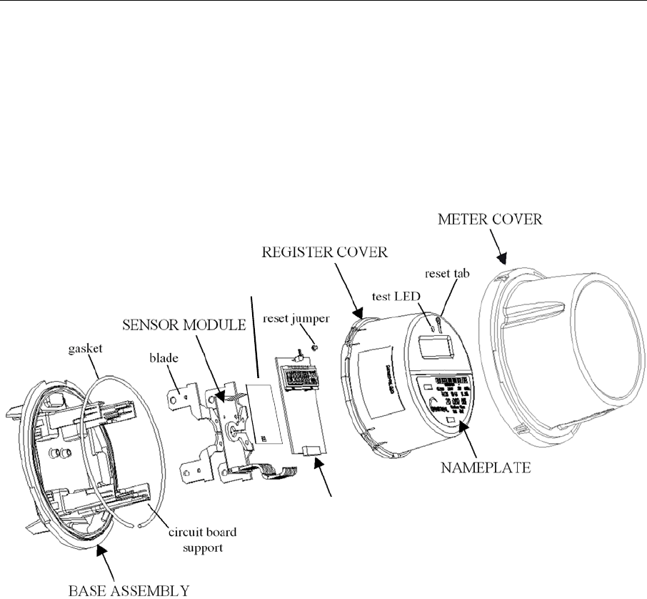
The iCon™ MXU 530-E Meter was designed to be assembled and disassembled
without the use of tools. This modular design allows you to upgrade or repair a unit
quickly and easily. The basic components of the iCon™ meter are depicted below and
detailed following the diagram.
MXU 530-E
DISPLAY BOARD
POWER SUPPLY
BOARD
Base Assembly
The meter’s Base Assembly is molded from highly durable thermoplastics that provide
a stable platform for the meter’s Sensor Module, Register display board and up to two
additional option boards. The blades (or blade assembly) from the Sensor Module
extend through the Base Assembly to connect to the service socket of the main power
system.
Sensor Module
Power Supply
The iCon™ meter uses a capacitive tap to provide a regulated voltage to the Sensor
Module and the LCD display portion of the MXU 530-E board. The power supply can
withstand a voltage transient as described in IEEE C62.41, Level C and applied in
accordance with Section 5 of the ANSI C12.20-1998.

iCon™ Form 2S and Form 12S Meters Physical Description
Current Sensor
Current is measured using a proprietary air-coupled current transformer. Sensor
data, quantities proportional to the time derivative of the current, is streamed to the
on-board metering chip.
Metering Chip
The iCon™ meter is pre-programmed at the factory for basic residential metering
where 1 Wh equals 230 internal energy units. The metering chip measures voltage
using a resistor divider, performs all energy calculations, and outputs billing data to
the Register display board.
The metering chip multiplies instantaneous current and voltage to calculate energy
usage. Energy is read and accumulated into the integer register once every line
cycle. The capacity of the internal register corresponds to 1024 Wh, and the total
energy capacity of the software data register before rollover is approximately ±8.5e6
kWh. Under typical conditions, the internal register has the capacity to store
approximately 80 years of metering data.
The computed watthours is output in a variable frequency pulse waveform and
instantaneous watt-hour. At calibration, the value of each pulse is set as close as
practical to 1.0 watthours per pulse. Each pulse, measured from the rising edge of an
output pulse to the rising edge of the next output pulse, is defined as the meter
energy constant Ke and can be provided as a test output.
Power supply board
This board utilizes the 120/240 VAC mains to supply a regulated voltage to the radio
portion of the MXU 530-E display board.
MXU 530-E display board
The LCD display portion of the board consists of a control processor (register), and
LCD display. The radio portion of the board consists of a spread spectrum direct
sequence radio used to transmit the electric meter data over the air. Modules for
advanced options, such as AMR, are integrated into the display board in the area
below the LCD display. The cable between the Register display board and the
Sensor Module carries SPI, interrupt, and pulse output signals.
Control Processor (register)
The control processor accumulates the active energy register data and converts the
readings to kWh. These active energy readings (or a short-term average of these
readings) are defined as “Instantaneous kWh”. The accumulation of these readings is
defined as “Total kWh”.
NOTE
During the normal operation of the meter, the Total kWh register can be
cleared, but cannot be set to a specific figure. Refer to Error! Reference
source not found. on page Error! Bookmark not defined..
The Total kWh displayed on the LCD, described below, is to the decimal resolution
specified at time of order. The full resolution of the Ke value is maintained in the

Physical Description iCon™ Form 2S and Form 12S Meters
meter’s memory for internal computation. All billing data and system information is
stored in the meter’s non-volatile memory. System information, compliant with ANSI
C12.19a data table format, includes the following:
User Data
Calibration Date Set by Invensys when the meter is first calibrated
User Configuration Date Set by the utility when the meter is configured for use
Serial Number 16 digit decimal serial number
Identification 20 decimal digits of identification data
kh Text representation of the kh value in kWh (default 0.0010)
kt Text representation of the kt value in kWh (default 0.0010)
Pulse Divider Pulse divider value (default 1.0)
User Data 16 bytes of free-format data for the utility to set as required
Manufacturer Data
Manufacturer Manufacturer ID code
Model Meter model number
Hardware/firmware Versions Hardware/firmware version numbers
Meter Form Meter form (2S)
Meter Class Amps Class amps as text string (200.0)
Meter Test Amps Test amps as text string (30.000)
Manufacturing Status Undefined manufacturing status information
Display
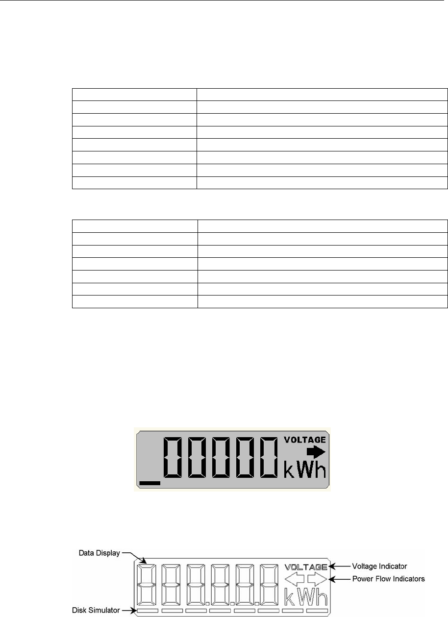
The Liquid Crystal Display (LCD) on the front of the meter shows real-time Total kWh
and indicates the current operational status of the meter. Information on the LCD is
visible in direct sunlight and can be read at angles of 15 degrees above and below
the display window’s centerline. The following graphic shows how the meter display
will look when first put into service.
The next graphic shows all available segments on the meter’s LCD and identifies the
standard features. Each feature is detailed in the following paragraphs.

iCon™ Form 2S and Form 12S Meters Physical Description
The Data Display is the set of large digits on the LCD screen that shows the data
quantities of the selected modes. Typically, the Total kWh is displayed in whole
numbers using five digits. Decimal resolution may be selected at time of order. Refer
to Error! Reference source not found., starting on page Error! Bookmark not
defined., for details on the Error and Alternate Display Mode options. During a power
outage, the display screen will not be active, however, all data is preserved in non-
volatile memory.
If enabled, Power Flow Indicators, the arrows to the upper right of the data display,
indicate the direction of the power flow, as shown in the following table. In the event
that power drops below the preset threshold of 25 watts neither arrow will be
displayed.
Normal flow.
This arrow indicates that the meter has detected delivered or positive energy that
was supplied to the customer from the distribution system.
Reverse flow.
This arrow indicates that the meter has detected received or negative energy that the
customer has supplied to the distribution system.
The enunciator above the power-flow indicators, the Voltage Indicator, appears
when sufficient AC volts are detected to ensure reliable operation of the meter. At
lower voltages, meter operation may continue. The voltage indicator is not visible if
the meter has encountered an error condition or is in alternate display mode, if these
display modes were selected at time of order.
If enabled, the Disc Simulator is an 8-segment bar that runs under the Data Display
and Voltage Indicator. In normal operating conditions, the Disc Simulator runs from
left to right, and increments once every watt-hour. In reverse power conditions, it runs
from right to left.
Register Cover
The Register Cover is an opaque shield that protects the meter’s internal boards from
external tampering and serves as the mounting surface for the nameplate. With the
exception of the LCD screen and test LED, no internal components can be viewed
through the Register Cover.
Nameplate
The meter’s nameplate, which is compliant with ANSI C12.10 – 1997, includes a
unique, factory-generated bar code that can be used in a billing database.
Meter Cover
The Meter Cover of each iCon™ meter unit is a transparent polycarbonate enclosure
that is interchangeable, abrasion resistant, and contains UV inhibitors to prevent
discoloration. This single-piece assembly locks with the Base Assembly to fully
enclose the meter and protect the internal components from weather, the forces
applied during installation and extraction, and the impact from a fall of up to five feet.
After final calibration at the factory, the Meter Cover and Base Assembly are sealed
with a T-bar, which will provide evidence of tampering.