Sensus Metering Systems XEMICS-BAT DTS/FHSS Transceiver User Manual 386285
Sensus Metering Systems DTS/FHSS Transceiver 386285
Users Manual

Invensys Metering Systems Page 1 of 7
Invensys Metering Systems, ICG – Robert
Shaw Radio Quick-Start Guide
8 October 2003
This document contains proprietary information. It may not be copied,
transmitted or distributed, in whole or in part, without the consent of Invensys
Metering Systems.

Test Plan
Invensys Metering Systems Page 2 of 7
Contents
Contents.....................................................................................................................2
1 INTRODUCTION..................................................................................................4
2 SETUP PROCEDURES .......................................................................................4
3 EXAMPLE............................................................................................................5
REVISION SUMMARY
date section change description
8 Oct 2003 Baseline document
9 Oct 2003 More screenshots and comments
Test Plan
Invensys Metering Systems Page 3 of 7
FCC Compliance
NOTE:
This equipment has been tested and found to comply with the
limits for a Class B digital device, pursuant to part 15 of the FCC
Rules. These limits are designed to provide reasonable protection
against harmful interference in a residential installation. This equipment
generates, uses and can radiate radio frequency energy and, if
not installed and used in accordance with the instructions, may cause
harmful interference to radio communications. However, there is no
guarantee that interference will not occur in a particular installation. If
this equipment does cause harmful interference to radio or television
reception, which can be determined by turning the equipment off and
on, the user is encouraged to try to correct the interference by one or
more of the following measures;
– Reorient or relocate the receiving antenna
– Increase the separation between the equipment and receiver
– Connect the equipment into an outlet on a circuit different from that
to which the receiver is connected
– Consult the dealer or an experienced radio/TV technician
WARNING:
No party shall make any modifications or changes to product circuitry
without the express written consent of Invensys Metering Systems. Doing so could
result in the equipment becoming non-compliant with the requirements of the Federal
Communication Commission Rules CFR47 Part 15 and could void the user’s
authority to operate the equipment.
Note: To comply with FCC RF exposure requirements in
section 1.1307, a minimum separation distance of 20 cm
(8 inches) is required between the antenna and all
persons.
Test Plan
Invensys Metering Systems Page 4 of 7
Introduction
This document contains instructions for setting up communication between multiple
Robert Shaw radios for testing purposes, and describes the use of the InvenStack
test software.
1 Setup Procedures
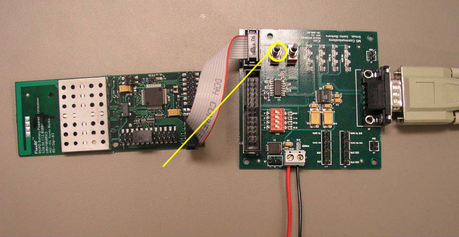
1. Connect the radio to the RS232 interface/control board via the 10 pin connectors
with a ribbon cable as shown in the photograph fig 1. Make sure that pin 1 on the
interface board is connected to pin 1 on the radio (both are near the edge of the
board). The interface board provides voltage level shifting between the PC and
the radio board.
2. Connect the interface board to a PC via a standard RS232 cable.
3. Provide 3.3V DC (limit to 80mA per radio) to the interface board at the
connections shown in the photograph fig 1. Current draw at 3.3V in on power-up
should be about 30mA per radio.
fig. 1 – Serial comm. and power connections
4. Start the InvenStack test application (start one for each radio) on the PC
(screenshot fig. 2). Set up serial communication with the radio in the Com menu.
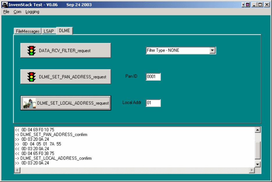
5. Set up the Filter Type, PanID and Local Address under the DLME tab. See fig. 2
below.
Rese
t
Test Plan
Invensys Metering Systems Page 5 of 7
fig 2. Setting up PanID and Local Address in DLME tab
6. Set up the log file if desired in the logging menu.
7. Under the FileMessages tab, browse to select individual files or batch files to run
to begin sending messages between radios. Each file contains a command, the
batch files can be used to loop or send consecutive commands with a user-
determined delay between each.
2 Example
The text below is from the message file DL_DATA_REQUEST_ACK_1.TXT. This
will send a DL_DATA_request command. This will result in a DL_DATA_confirm
from the InvenStack on the sending radio. This DL_DATA_confirm on the sending
radio will indicate if the message was successfully transmitted. If AckMode is set to
ACK_MONITORING (on) in the DL_DATA_request message, then a success in that
confirm indicates that the RF ACK was received from the intended recipient of the
message. The message contains the sample Lsdu data 01 02 03 04 05. All radios
within range will receive the message. On all those with Filter Type NONE an
Indication will result. On all those with Filter Type PAN ID, an Indication will result if
the radios’ PanID matches that in the message (0x0001). On all those with Filter
Type set to LOCAL ADDR, and Indication will result if the radios’ LocalAddress
matches that in the message (0x02). On all those with Filter Type PAN AND
LOCAL, an Indication will result only if both the PanID and LocalAddress of the
radio matches the message. Regardless of the filter setting, an ACK will be
generated by the receiving radio if and only if both the PanID and LocalAddress in

Test Plan
Invensys Metering Systems Page 6 of 7
the received message match those set in the receiving radio. The original sender
will accept that ACK generated by the receiving radio if and only if the SrcPanID
and SrcAddr in the original message are correct. Below are a few steps that can be
followed to verify proper communication and a couple of screenshots that show the
resulting messages in the test applications message windows. The file
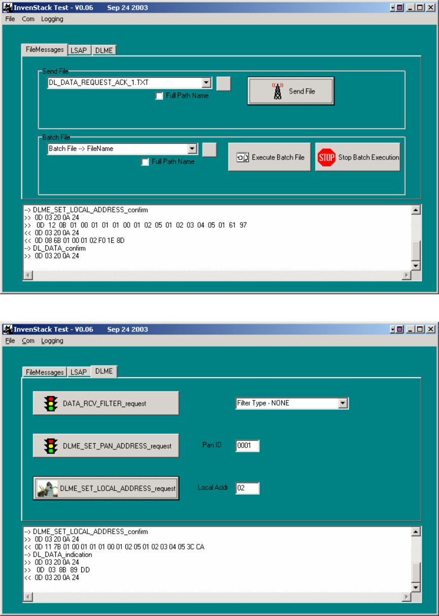
DL_DATA_REQUEST_ACK_1.TXT contains the following text. In the screenshot in
fig. 3, this message has just been sent out and can be seen on the third line in the
message window.
/ This is a test Output File #1
0x0D
0x12 // Length of remaining bytes including CRC
0x0B // DL Data Request
0x01 // Src Addr mode = 8
0x00
0x01 // Pan Id = 0x0001
0x01 // Src Addr
0x01 // Dest Addr Mode = 8
0x00
0x01 // Dest Pan ID = 0x0001
0x02 // Dest ID = 2
0x05 // Lsdu Length
0x01
0x02
0x03
0x04
0x05
0x01 // Ack Monitoring (on)
CRCMSB //CRC PlaceHolders
CRCLSB
Steps to verify communication between two radios:
1. Connect both radios to RS232 interface boards and power as described
above.
2. Power on both radios.
3. Start the test application for each radio.
4. Set the Filter Type, PanID and Local Address for both radios. For a simple
test use PanID 0x0001 and Local Address 0x01 for the sending radio and
PanID 0x0001 and Local Address 0x02 for the receiving radio and send the
file above which matches these settings.
5. Sending the file DL_DATA_REQUEST_ACK_1.TXT above should result in a
DL_DATA_confirm showing 0xF0 DL_SUCCESS on the sending radio and
an Indication on the receiving radio (see fig. 4 below). Since AckMode is set
to ACK_MONITORING (0x01) in the message, this confirms that the RF ACK
was successful. The message windows on the test apps used should look
like the screenshots below.
Test Plan
Invensys Metering Systems Page 7 of 7
fig. 3 InvenStack Test application – Radio 0001, 01 just sent message
fig. 4 InvenStack Test application – Radio 0001, 02 just received message