User Manual
Installation and Operation Guide
1
Installation and Operation Guide
DMR Repeater
SBR8040/SCR8040/SER8040

Installation and Operation Guide
1
General
This guide contains the installation and basic operating
instructions for the DMR Repeater models SBR8000, SCR8000
and SER8000. This guide does not contain information relating
to the installation of accessories such as the antenna and
duplexer. Refer to the installation instructions supplied with
these accessories for further safety and installation instructions.
Disclaimer notice
Sepura’s policy is to continually improve its products. The
features and facilities described in this document were correct at
publication, but are subject to change without notice.
Contact Us
Sepura plc.
Radio House,
St Andrew’s Road,
Cambridge CB4 1GR
United Kingdom
Tel: +44 (0)1223 876000
Fax: +44 (0)1223 879000
© Sepura plc. 2014
SPR-DOC-03800/1
Original Instructions: ENGLISH
All rights reserved. This document is intended for the use of Sepura plc’s customers
and/or other parties only for the purposes of the agreement or arrangement under
which this document is submitted, and no part of it may be reproduced or transmitted
in any form or means without the prior written permission of Sepura plc.
Contents
Safety ........................................................................................ 2
Regulatory ................................................................................ 4
Disposing of this product ............................................. 4
Technical specification ........................................................... 5
Controls, connectors and components ................................. 7
Status indicators ...................................................................... 7
Unpacking................................................................................. 8
Accessory information ............................................................ 8
Installation ................................................................................ 9
Guidelines and recommendations ................................ 9
Wall-mount bracket installation.................................... 9
Attaching the desk mount feet ................................... 10
Connections ........................................................................... 11
AC power supply ....................................................... 11
DC power supply ...................................................... 11
Antenna ................................................................... 11
Basic operation ...................................................................... 12
Power on/off ............................................................ 12
Voice and data transfer ............................................. 12
Alarm mode ............................................................. 12
Configuring the Repeater .......................................... 12
Caring for your product......................................................... 13
Duplexer specifications ........................................................ 13

DMR Repeater SBR8000, SCR8000, SER8000
2
Safety
Read these safety instructions carefully.
Attention!
This product is restricted for occupational use and is not
intended or authorised for use by the general population.
It is the responsibility of the person operating the product to
ensure that it is operated safely at all times, and that local laws
and regulations governing the usage of Radio Frequency (RF)
products are observed.
Users must be trained to operate this product safely. Their
personal safety could be affected if they do not understand how
to operate this product correctly.
CAUTION! Product weighs 12.5 Kg, take care when lifting.
Exposure to RF energy
Sepura designs and manufactures products to meet strict
guidelines and international standards relating to Radio
Frequency energy and the potential health risks associated with
using such products.
This product contains radio transmitters and receivers that
receive and transmit Radio Frequency (RF) signals when
switched on. The antenna radiates RF energy only when
transmitting and not in standby mode.
Users should be informed of the potential health risks
associated with long term exposure to RF energy by their
employer.
RF energy interference with electronic equipment
Some personal medical devices, such as hearing aids and
pacemakers, can be affected by RF energy. Always consult your
service provider or the manufacturer of the medical device
before using RF wireless devices.
Accessories
Sepura products have been tested to meet strict guidelines for
personal safety and operational conditions. Only accessories
approved by Sepura are recommended for use with this product.
Always read the instructions supplied with the accessory for
additional safety instructions.
Unauthorised modifications to the product could cause the
product to become non-operational and void any product
warranty.
The use of non-approved accessories may invalidate any
product warranty and may compromise the product safety
ratings.
Servicing
Do not attempt to dismantle this product.
Servicing and repairs to this product must be performed by
trained service technicians at Sepura approved service centres.
CAUTION! This product has double pole/neutral fusing.
FCC NOTICE
Any Changes or modifications not expressly approved by the
party responsible for compliance could void the user’s authority
to operate the equipment.
This device complies with part 15 of the FCC Rules. Operation
is subject to the following two conditions: (1) This device may
not cause harmful interference, and (2) this device must accept
any interference received, including interference that may
cause undesired operation.
FCC Radiation Exposure Statement:This equipment complies
with FCC radiation exposure limits set forth for an controlled

Installation and Operation Guide
3
environment. The antenna should be installed and operated
with minimum distance 1.0m from human body.
This transmitter must not be co-located or operating in
conjunction with any other antenna or transmitter.
Note: This equipment has been tested and found to comply
with the limits for a Class A digital device, pursuant to part 15 of
the FCC Rules. These limits are designed to provide
reasonable protection against harmful interference in a
residential installation. This equipment generates uses and can
radiate radio frequency energy and, if not installed and used in
accordance with the instructions, may cause harmful
interference to radio communications. However, there is no
guarantee that interference will not occur in a particular
installation. If this equipment does cause harmful interference
to radio or television reception, which can be determined by
turning the equipment off and on, the user is encouraged to try
to correct the interference by one or more of the following
measures:
—Reorient or relocate the receiving antenna.
—Increase the separation between the equipment and receiver.
—Connect the equipment into an outlet on a circuit different
from that to which the receiver is connected.
—Consult the dealer or an experienced radio/TV technician for
help.
IC Warning
This device complies with Industry Canada licence-exempt RSS
standard(s). Operation is subject to the following two conditions:
(1) this device may not cause interference, and (2) this device
must accept any interference, including interference that may
cause undesired operation of the device.
Le présent appareil est conforme aux CNR d'Industrie Canada
applicables aux appareils radio exempts de licence.
L'exploitation est autorisée aux deux conditions suivantes:
(1) l'appareil ne doit pas produire de brouillage, et
(2) l'utilisateur de l'appareil doit accepter tout brouillage
radioélectrique subi, même si le brouillage est susceptible d'en
compromettre le fonctionnement.
The term “IC:” before the certification/registration number only
signifies that the Industry Canada technical specifications were
met.Under Industry Canada regulations, this radio transmitter
may only operate using an antenna of a type and maximum (or
lesser) gain approved for the transmitter by Industry Canada. To
reduce potential radio interference to other users, the antenna
type and its gain should be so chosen that the equivalent
isotropically radiated power (e.i.r.p.) is not more than that
necessary for successful communication.
Conformément à la réglementation d'Industrie Canada, le
présent émetteur radio peut fonctionner avec une antenne d'un
type et d'un gain maximal (ou inférieur) approuvé pour
l'émetteur par Industrie Canada.
Dans le but de réduire les risques de brouillage radioélectrique à
l'intention des autres utilisateurs, il faut choisir le type d'antenne
et son gain de sorte que la puissance isotrope rayonnée
équivalente (p.i.r.e.) ne dépasse pas l'intensité nécessaire à
l'établissement d'une communication satisfaisante.
This radio transmitter (identify the device by certification number,
or model number if
Category II) has been approved by Industry Canada to operate
with the antenna types listed below with the maximum
permissible gain and required antenna impedance for each

DMR Repeater SBR8000, SCR8000, SER8000
4
antenna type indicated. Antenna types not included in this list,
having a gain greater than the maximum gain indicated for that
type, are strictly prohibited for use with this device.
Le présent émetteur radio (identifier le dispositif par son numéro
de certification ou son numéro de modèle s'il fait partie du
matériel de catégorie I) a été approuvé par Industrie Canada
pour fonctionner avec les types d'antenne énumérés ci-dessous
et ayant un gain admissible maximal et l'impédance requise
pour chaque type d'antenne. Les types d'antenne non inclus
dans cette liste, ou dont le gain est supérieur au gain maximal
indiqué, sont strictement interdits pour l'exploitation de
l'émetteur.
IC Radiation Exposure Statement: This equipment complies
with IC RF radiation exposure limits set forth for an controlled
environment. This transmitter must not be co-located or
operating in conjunction with any other antenna or transmitter.
The antenna should be installed and operated with minimum
distance 1.0m from human body.
Regulatory
Sepura declares that this product is complaint
with the essential requirements and other
relevant provisions of the European R&TTE
directive 1999/5/EC relating to radio and
telecommunications terminal equipment and the
mutual recognition of their conformity. This product is also
compliant with directive 2011/65/EU having been designed and
manufactured to the RoHS requirements.
Disposing of this product
This symbol on the product or its packaging
indicates that this product must not be disposed of
as household or commercial waste. Some
countries have set up collection and recycling
systems for waste electrical and electronic
products. By ensuring that this product and its
packaging is disposed of correctly, you will help
prevent potentially negative consequences for the environment
and human health, and help conserve natural resources. Please
dispose of your waste product according to your national and
local regulations. Contact Sepura or your Service Provider for
information about disposing of this product in your region of the
world.

Installation and Operation Guide
5
Technical specification
Frequency Range ................................................... 400-470 MHz
Dimensions (WxDxH) ................. 482.5 x 338.5 x 132.5 mm (3U)
Weight .............................................................................. 12.5 Kg
Power Supply AC ............................... 100-120V@2.5A 50/60 Hz
200-240V@1.5A 50/60 Hz
Power Supply DC ........................................... 10.8 – 15.6V@15A
DC Fuse ....................................................................... 13.6V15A
AC Fuse .................................................2.5A 250V AC, 5x20mm
Fuse Type ......................................... HRC ceramic, Time lag (T)
Power Rating ...................................................................... 240W
Transmitter Power Output .....................................................40W
Working temperature range ................ -30 to 60oC (-22 to 140oF)
For more technical information about this product, refer to the
product technical datasheet available from our website.
DMR Repeater SBR8000, SCR8000, SER8000
6
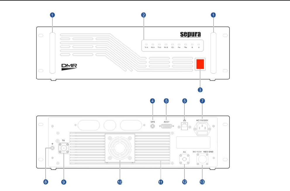
Front Panel
Rear Panel
Installation and Operation Guide
7
Controls, connectors and
components
Refer to the illustration for the location of the following controls,
connectors and buttons.
(1) Handles
(2) Status indicators
(3) Power switch
(4) GPS antenna connector
(5) Accessory connector
(6) Ethernet (RJ45) connector
(7) AC power input connector with fuse holder
(8) Grounding point
(9) Transmit antenna connector (N-type)
(10) Fan
(11) Heat sink
(12) Receive antenna connector (BNC)
(13) DC connector
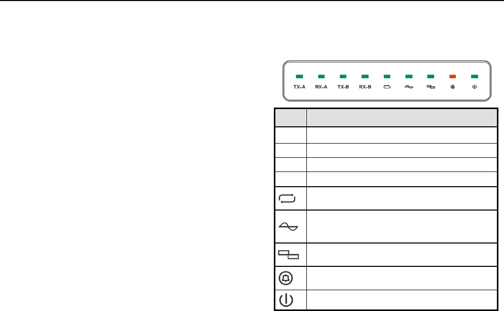
Status indicators
The Repeater has a series of LEDs on the front panel that
indicate various operational states.
LED Description
TX-A Indicates slot 1 is transmitting
RX-A Indicates slot 1 is receiving
TX-B Indicates slot 2 is transmitting.
RX-B Indicates slot 2 is receiving
Repeater mode. When illuminated, the repeater is
active. When the repeater is inactive, the LED is off.
Analogue mode. For analogue or mixed signals the
LED flashes when active. When inactive the LED is
off.
Digital mode. For digital or mixed the LED flashes
when active. When non-active the LED is off.
Alarm mode. Illuminates when there is a problem
with the repeater. See Basic Operation.
Illuminates when the repeater is switched on.

DMR Repeater SBR8000, SCR8000, SER8000
8
Unpacking
(1) DMR Repeater
(2) Desk mount feet with screws (4 pieces)
Unpack the contents of the box and ensure that all items are
received in good condition. If any of the goods are damaged or
not supplied, notify your Service Provider within 10 days of
receipt of the equipment.
Accessory information
Sepura supply a range of accessories for this product. Contact
your Service Provider or visit our website for a full list of
accessories.
Accessory Part No.
Wall mount bracket 300-01071
AC Power cable (UK) 300-01139
AC Power cable (EU) 300-01141
AC Power cable (US) 300-01138
AC Power cable (AUS) 300-01140
Repeater Battery Backup cable 300-01067
1
2
Installation and Operation Guide
9
Installation
Guidelines and recommendations
It is important that the repeater does not exceed the working
limits detailed in the technical specification section of this guide.
When rack mounting the repeater, ensure sufficient air flow to
prevent overheating and secure the unit within the rack system.
Cabling should be carefully routed and secured to prevent
connections becoming loose.
When desk mounted, always attach the four desk mount feet to
the repeater. The desk must have a flat level surface. The
repeater creates low level background noise and it is
recommended that it is not located in an office environment.
It is recommended that when wall mounted, it must be
positioned so that it is clearly visible to personnel to reduce the
risk of personal injury by collision. Ensure sufficient air flow to
prevent overheating. Cabling should be carefully routed and
secured to prevent a trip hazard and connections becoming
loose.
The repeater has a battery backup facility that maintains service
in the event of an AC power supply failure. It is recommended
that both AC and DC power supplies are connected to the
repeater to prevent loss of service. If the AC power supply fails,
the repeater will shut down and reboot using the DC power
supply. Time taken to reboot using the DC supply is typically 60
seconds. When the AC supply is restored, the repeater will
switch to the AC supply automatically without a reboot.
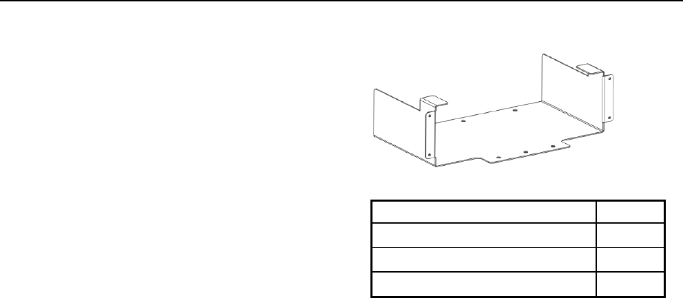
Wall-mount bracket installation
The wall-mount bracket is supplied with the following items:
Item Qty
ST6 x 35 expansion screw 6
M5 x12 screw 4
Plastic plug 6
Only attach the wall bracket to a solid wall using the fixings
supplied.
Use the bracket as a template to position the holes on the
wall. Ensure that the bracket is level. Use a small punch or
pencil to mark the position of the holes on to the wall.
Drill 6mm diameter holes on the wall in the positions marked
and drill to a depth to suit the length of the plastic plugs and
screws. Insert the plastic plugs into the holes.
DMR Repeater SBR8000, SCR8000, SER8000
10
Hold the bracket securely, keeping it level. Secure into
position using the ST6 x 35 expansion screws. Ensure that
the bracket is secure and level.
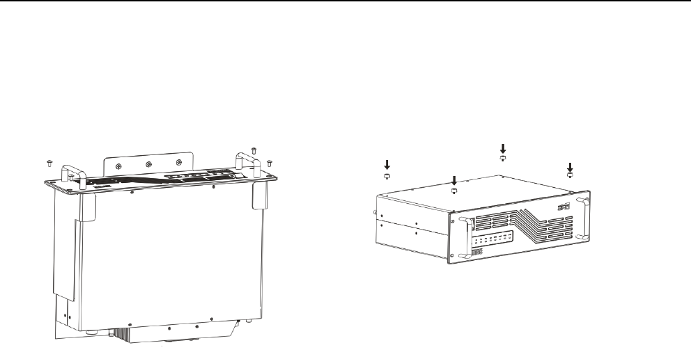
Remove the desk mount feet (if fitted) from the repeater.
With the top of the repeater against the wall, slide the
repeater into the bracket.
Secure the repeater to the wall bracket using the four M5 x 12
screws as shown.
Attaching the desk mount feet
If the repeater is installed onto a desk or bench, the four screw
type desk mount feet, supplied with the product, should be
attached.
Using a soft cloth or rubber mat to protect the external surfaces,
place the repeater with the underside facing upwards, onto a flat
surface.
Secure the feet into position using the screws supplied.

Installation and Operation Guide
11
Connections
All connectors are located on the back panel of the repeater.
Ensure that the cables are routed so that they are kept well clear
of the antenna cable.
Route cables carefully to eliminate the possibility of damage by
sharp edges. Ensure all cabling is secured and routed to avoid
the risk of a trip hazard.
AC power supply
Connect AC power supply to the 110/240V AC power input
connector.
Connect the repeater grounding point to an appropriate earthing
point.
DC power supply
The Repeater Battery Backup cable (optional) is required to
connect the repeater to the DC power source.
Connect the repeater grounding point to an appropriate earthing
point.
Connect the cable to the DC connector on the repeater.
Connect the red wire to the positive terminal on the DC power
source.
Connect the black wire to the negative terminal on the DC power
source.
If the power cable needs to be shortened, it must be shortened
from the DC power source connection end. A fuse must be fitted
to the positive line (red wire) when the cable has been
shortened. A new fuse holder must be fitted (not supplied)
because the existing fuse holder cannot be reused. The fuse
must be positioned close to the DC power source positive
terminal.
CAUTION! Failure to connect the wires to the correct terminal of
the battery or power supply may damage the product and void
any warranty.
CAUTION! DO NOT extend the Repeater Battery Backup cable.
This will affect the backup operation.
Antenna
In order to reduce the risk of RF burns, the antenna must always
remain connected whilst the equipment is switched on. Under no
circumstances should the antenna be connected or
disconnected whilst the equipment is switched on. Do not touch
the antenna when the repeater is switched on.
CAUTION! Do not operate the repeater without an appropriate
RF load attached.

DMR Repeater SBR8000, SCR8000, SER8000
12
Basic operation
Power on/off
To switch the repeater on, operate the Power on/off switch. The
Power on/off status indicator illuminates and the repeater runs a
start-up test routine that takes approximately 60 seconds. The
Alarm indicator illuminates for the duration of the test. On
completion of the test routine, the Analogue mode or Digital
mode indicator (depending on the selected active channel
preference) illuminates.
To switch the repeater off, operate the Power on/off switch.
Voice and data transfer
The repeater uses different frequencies when receiving and
transmitting. Received signals that are weak due to attenuation
are amplified and transmitted at a higher strength than received.
When transmitting, the repeater mode indicator illuminates. If
the repeater is transmitting an analogue signal, the Analogue
mode indicator flashes when transmitting. If the transmitting
signal is digital the Digital mode indicator flashes when
transmitting.
The frequency and DCS/CTCSS for analogue signals, is
configured using the DMR Manager software.
Alarm mode
The Alarm indicator on the front panel illuminates when certain
operational states warrant. When the repeater is in start-up
mode, the LED remains illuminated for the duration of the start-
up routine (approx. 60 seconds).
LED state Alarm condition
Illuminated for more
than 60 seconds
The internal temperature exceeds
the working limits.
or
Rx and Tx PLL (Phased Lock Loop)
have failed.
or
Tx VSWR (Voltage Standing Wave
Ratio) is incorrect.
Flashing once every
second
Rx PLL failure.
Flashing every two
seconds
Tx PLL failure.
Configuring the Repeater
The repeater is configured using the DMR Manager software run
from a computer connected directly to the repeater or over a
network.
Connect a standard LAN/WAN cable (RJ45 connector) to the
Network connector on the repeater with the other end connected
to either a computer or network connection.
The default IP address for the repeater is 192.168.1.100. This
address can be changed using the programming software.

Installation and Operation Guide
13
Caring for your product
The product does not require regular servicing. Caring for your
product as described in this guide will help maintain the product
in good operational condition.
Always wear eye protection when using brushes or other tools to
clear debris from connectors or other parts of the product.
Do not use chemicals, aerosols or abrasive cleaners. Chemical
coatings must not be applied to any part of the terminal or
battery.
Clean the exterior surfaces using a lint free soft cloth.
Check cable connections regularly to ensure that they are
secure.
Duplexer specifications
An optional duplexer can be used with the repeater. The
duplexer allows the repeater’s receiver and transmitter to
operate on a single antenna at the same time. When operating
within neighbourhoods where other RF devices are installed,
including broadcast antennas and microwave link transmitters,
the duplexer prevents interference with other RF devices.
The duplexer can be connected externally to the repeater.
The duplexer must comply with the recommended technical
specifications below:
Frequency Range .................................................... 400-470MHz
Bandwidth .................................................................... ±400KHz
Insertion Loss.................................................................... <1.0dB
Isolation.............................................................................. >80dB
Suppression ....................................................................... >80dB
V.S.W.R ................................................................................ <1.3
Nominal Impedance ............................................................... 50Ω

Sepura plc
Radio House
St Andrew’s Road
Cambridge
CB4 1GR
UK
Tel: +44 (0)1223 876000
Fax: +44 (0)1223 879000
Sepura.com