Sepura STP8280 Portable TETRA Radio User Manual STP CK Manual final version1 2
Sepura plc Portable TETRA Radio STP CK Manual final version1 2
Sepura >
Contents
STP_CK_Manual_final version1_2
STP8000 Series CAR KIT
INSTALLATION & USER GUIDE
1
sepura
INTRODUCTION
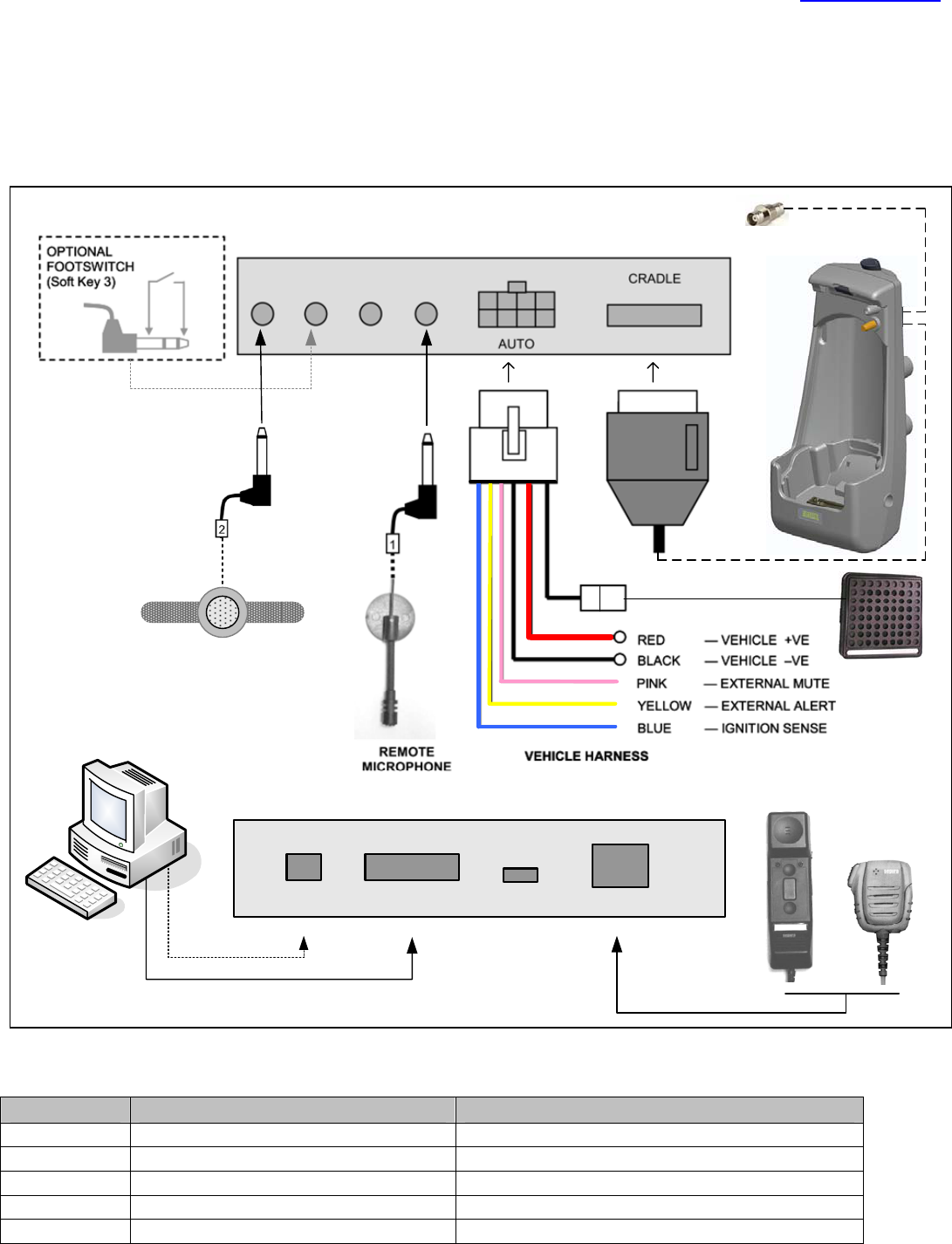
The STP8000 car kit provides secure retention of the radio within a cradle. The car kit features battery charging, external
antenna connection, external PTT keypad, hands-free operation with the external microphone and loudspeaker. A standard
RS232 data port and USB is provided for data transfer applications. Connections are provided for optional accessories.
Cable colour Electrical parameters Fuse
RED Vehicle +ve (12v MAX) 4 Amp
BLACK Vehicle –ve (vehicle chassis) n/a
PINK Open drain Output, max current 0.5A Protected by a re-settable fuse provided inside car kit
YELLOW Open drain Output, max current 0.5A Protected by a re-settable fuse provided inside car kit
BLUE Input Signal Level 12VDC (200 uA max) 1 Amp
sepura
or
MICSMICALARMPTT
REMOTE PTT
CRADLE
Front INTERFACE UNIT (user interface)
USB DATA (RS232) SXC HANDSET/FIST MIC
Loudspeaker Output
50Ω
Rear INTERFACE UNIT (vehicle harness)
Antenna
Connections for accessories

STP8000 Series CAR KIT
INSTALLATION & USER GUIDE
2
sepura
Information
The STP8000 car kit is designed for 12 V negative earth
systems. In vehicles with a 24 V supply, an approved
converter must be used, NOT a 12 V tap on the battery.
The equipment is to be installed in accordance with the
requirements of local radio communications authorities
and/or Health and Safety regulations.
12 V supply leads, antenna cables and speaker wiring is to
be routed as far away as possible from gas or fuel lines.
This reduces the risk to safety in the event of a leak.
The car kit should be positioned so that it does not obstruct,
or become at risk of damage from, any occupant or carried
items. All cabling should be hidden and not left loose.
Radio Software
For correct operation of the STP8000 with the car kit, the
STP8000 must have radio software of v9.0 greater.
INSTALLATION
This installation guide provides basic installation information
and is not intended to be definitive, as different types of
vehicles will require different ways installation arrangements.
The installer must ensure that fixing screws of an appropri-
ate length are used (some installations may require different
screws). The information given here is general and for guid-
ance only.
The installation must comply with in-country CODE OF
PRACTICE for the installation of mobile radio and related
ancillary equipment in land based vehicles — e.g. FCS1362
(formally MPT1362)see http:// www.fcs.org.uk.
WARNING
1 Disconnect the vehicle’s battery before commencing
installation (be aware of effect on public broadcast radio
security code, alarm systems and some engine man-
agement systems).
2 Do not smoke, or use naked flames, when working near
the vehicle’s fuel system.
3 Ensure that fuel lines, hydraulic lines and existing
cables are not damaged during installation.
4 Ensure that the installation does not impede the normal
operation of the vehicle, including the operation of any
safety device, e.g., airbags and seatbelt tensioners.
5 Speed control, fuel injection, anti-lock braking, naviga-
tion, air bag and other electronic systems are relatively
immune to RF interference. However, if difficulty is
experienced, or faulty operation suspected, consult the
vehicle’s dealer.
6 This equipment is suitable for 12 V negative earth vehi-
cles only. Use on other supply systems will result in
damage to the equipment.
7 No part of the equipment should be mounted such that
injury to the occupants is likely during an accident.
8 Prolonged operation of the radio in the car kit with the
vehicle engine switched off, could drain the vehicle’s
battery.
9 Prolonged operation at high volume levels may cause
the interface unit to become hot.
Cradle
The cradle should be attached to the vehicle’s interior in a
convenient position using the mounting brackets. The
location of the cradle should allow the user unrestricted
access to the radio’s controls. The radio’s display should be
visible to the user but not distracting when driving. The
cradle should not prevent the user from controlling or
operating the vehicle.
Interface Unit
Attach the interface unit to the vehicle’s interior, using, if
appropriate, the four 25mm self-tapping screws provided.
The interface unit should be mounted on a firm surface in-
side the passenger compartment, within reach of all cabling.
The data socket should be easily accessible. Connect the
lead from the cradle to the socket labelled “RADIO”. Con-
nect the vehicle harness to the socket labelled “AUTO”.
Note: Do not install the interface unit in engine compartment.
Cables & Connectors
Ensure the cables due not rub against sharp edges and are
not subjected to undue stress.
Power Connection (thick red and black wires)
• The positive power line must include a fuse as close as
possible to the power source. The negative power line
must be connected close to the battery-to-vehicle-body
connexion (not directly to the battery) and must not
include a fuse.
• It is recommended that the power cable runs are kept as
short as possible.
• The blue wire provides an ignition sensing input. If
ignition switching is required, trim the wire to length so
that it can be wired, via a fuse, to the ignition switch,
using the splicing connector provided. Otherwise this
wire must be connected, via a fuse, to the permanent
positive supply. A fuse must always be fitted close to
where the wire is connected.
Fuse Ratings
Positive supply 4 A Ignition sense 1 A
The ring terminated wires are for direct connection to the
vehicle battery (do not connect at this stage); supply should
not be taken from any other point.
Feed the bullet terminated free ends through the bulkhead,
using a grommet to protect the wires. Locate the free ends
under the dashboard and connect to the main wiring har-
ness supplied with the car kit. Connect the ring terminals to
the vehicle battery when the rest of the installation (see fol-
lowing sections) is complete and satisfactory.
Remote Microphone
The remote microphone is a high performance noise can-
celling type. For best results it should be directed towards

STP8000 Series CAR KIT
INSTALLATION & USER GUIDE
3
sepura
the user and located at a distance of (15 – 25) cm from the
user’s mouth. It is primarily intended for use in cars and light
goods vehicles. The recommended positions are on the “A”
pillar (for driver only) or centre-front of roof (for driver and
front passenger). For larger vehicles, greater distances can
be accommodated by increasing the remote microphone
gain via the customising file in the radio. However, the noise
and echo cancelling performance of the car kit may be com-
promised.
Mount the microphone using the self-adhesive Velcro™
mounting supplied. Alternatively, for rugged applications,
secure the base with self-tapping screws. Plug the micro-
phone into the jack socket labelled “MIC”.
PTT
The PTT keypad should be mounted to be convenient to the
user when in a normal driving position. Plug the PTT into the
jack socket labelled “PTT”. Mount the PTT using the self-
adhesive Velcro™ mounting supplied.
Loudspeaker Installation
The loudspeaker should be positioned so that it is unob-
structed and clearly audible by the user, but not close to, or
in line of sight of, the remote microphone. The recom-
mended position is in the passenger footwell, facing the
driver.
Connect the loudspeaker lead to the 2-pin flying connector
on the vehicle harness.
Antenna Installation
Follow the manufacturer’s instructions supplied with the
antenna. Connect the BNC plug to the flying lead from the
cradle and secure the leads.
Ignition Sense Input (blue wire)
If used, remove the crimp terminal from the blue wire and
connect it to the ignition switched supply.
If not used, plug the crimp terminal into the spare receptacle
in the plug housing of the main wiring harness supplied with
the car kit. Fold (do not coil) the spare wire together and
secure.
External Mute Output (pink wire)
If the vehicle has an entertainment system with a standard
external mute control, connect this output directly to it. Dur-
ing a call, the output switches to ground and the entertain-
ment system is muted. Use the appropriate connector for the
entertainment system installed.
If the entertainment system has no mute control, the exter-
nal mute output can be used to enable a relay to control the
loudspeakers. When enabled, the output is switched to
ground and protected by an internal re-settable 0.5 A fuse
which resets automatically when the fault is cleared.
If not used, fold (do not coil) the spare wire together. Insu-
late the free end and secure.
External Alert Output (yellow wire)
If local regulations permit, this output can be used to enable
a relay (not for direct connection) to control the vehicle horn
or other external alerting device. During a call alert, this out-
put switches to ground and the alerting device is audible
outside the vehicle. It is protected by an internal re-settable
0.5 A fuse which resets when the fault is cleared.
If not used, fold (do not coil) the spare wire together. Insu-
late the free end and secure.
IMPORTANT
To avoid possible damage to the interface unit, check all
wiring for short circuits to chassis, and other errors, before
power is connected.
OPTIONAL ACCESSORIES
Handset/Fist Microphone (or Speaker microphone) &
Soft Key
Mount the rest so that it is easily accessible to the user.
Place the accessory on its rest. Plug the accessory into the
RJ45 socket labelled “HANDSET / FIST MIC”. For strain
relief, fit the “P” clip to the cable and secure with one of the
interface unit fixing screws.
The soft key is located at the top of the fist microphone.
Alarm Foot-switch (Soft Key 3)
This item is not supplied by Sepura plc. A suitable switch will
be terminated in a 3.5 mm stereo jack plug with the switch
connected between the sleeve and the tip and the ring open
circuit. The alarm will be activated when the switch closes
(Z < 100 Ω).
OPERATION
SAFETY WARNING
DO NOT operate your STP8000 radio in an explosive
atmosphere. Always comply with “Turn OFF Two-way
radios” signs where these are posted
• Inserting the STP8000 radio into the cradle
If necessary, remove the rubber bungs from the
radio facility socket and the antenna socket. Lower
the STP8000 into the holster and push down lightly
to fully engage with the facility socket in the bottom
of the holster. Push the front of the radio towards
the back of the cradle until the latch operates. The
car kit switches on automatically when the radio is
inserted.
Note: To maintain reliable aerial operation, clean
the holster aerial connector regularly using an
aerosol can of clean air.
• Removing the STP8000
Press the release button at the top of the cradle and
withdraw the radio. The car kit switches off
automatically when the radio is removed and draws
negligible power from the vehicle’s battery.

STP8000 Series CAR KIT
INSTALLATION & USER GUIDE
4
sepura
Using the STP8000 series with the car kit
All of the controls on the radio function as normal. Calls can
be initiated, answered and ended by using the controls on
the radio. Refer to the STP8000 user guide for further
details. Receive audio is amplified and fed to the car kit
loudspeaker. The user’s voice is picked up by the hands-
free remote microphone, which should, ideally, be facing
towards the user.
• Volume Control
Set the loudspeaker volume with the radio’s volume
control.
• Half-Duplex Calls using Remote Microphone & PTT
Press the external PTT button and speak in a normal
conversational manner; release to listen.
• Full-Duplex Calls using the Remote Microphone
Both parties can speak and listen at the same time with
hands free. Ensure that the radio volume is set to the
minimum comfortable level.
Calls using Optional Accessories
A fist microphone may be used with the car kit. The car kit
automatically senses which is in use and functions as
appropriate.
• Fist Microphone
When the fist microphone is lifted, the remote microphone
is automatically muted, but the loudspeaker remains in use.
Press the PTT button on the fist microphone to talk and
release to listen. Any alert tones produced by the radio
during transmit will override the loudspeaker muting and be
audible.
• Fist Microphone soft key
The soft key of the fist microphone, invokes the assigned
function programmed in the STP8000 being used.
• Private/Public Mode Key (on radio, if programmed)
During calls, this key switches between accessories (e.g.,
transfer from handset to handsfree).
• Alarm Foot-switch
Press the foot-switch to initiate an emergency call.
• Data Communication
An RS232 serial data port and an USB serial port is
provided in the interface unit. Connect a PC or data
terminal (with appropriate application software) to the
socket labelled “DATA” via a standard 9-way serial lead
(not null modem). Follow the instructions supplied with the
application software. Disconnect lead from interface unit
when not in use.
Optional Functions
The following functions are provided as standard and will be
connected if specified prior to installation.
• Ignition Sense
If connected, the radio will sense the state of the ignition
switch. When the ignition is turned off, a configurable timer
is started. If the timer is set to zero, turning off the ignition
switch switches off the radio. If the timer is not set to zero,
the following message is displayed and the timer started.
Press any key to stop switch off.
Pressing any key will reset the timer. When the timer period
expires, the radio will switch off and any unread messages
will be lost.
If the ignition switch is turned on before the timer expires,
normal operation will resume.
The timer parameters are set in the radio configuration.
Charging is not halted by switching off the radio.
• External Mute
If connected, the vehicle entertainment system will be
muted during calls.
• External Alert
If connected, the vehicle’s horn, or other external sounder,
repeats incoming call alerts for audibility outside the vehicle
in noisy environments. Note: This function must not be
used if local regulations do not permit its use.
Battery Charging
The battery charges whether the STP8000 is switched on or
off and terminates automatically. The indicator LED on the
radio glows orange during charging, green when charged
and red under fault conditions — see STP8000 radio user
guide for further information.
Problems and Hints
If the car kit or radio fails to function, check the following.
• The radio is properly engaged in the cradle.
• If ignition sensing is enabled, check ignition is switched on.
• The battery may be discharged (the radio requires battery
power to transmit). Allow the battery to charge.
• The radio functions correctly when removed from the car
kit.
• The in-line fuses to the vehicle battery have not failed.
• The vehicle battery is not discharged.
• The antenna and its connections are functional.
If the problem persists, refer to your supplier.
Sepura plc, Radio House, Issue 1.2 (08/09)
St. Andrew’s Road, Cambridge,
CB4 1GR. England.
www.sepura.com
Public mode (default)
Handsfree:
Remote microphone
and Loudspeaker
Private mode
Handset/Fist Microphone
and Loudspeaker