Sequel Technologies SMKX01 Smoke Detector, Wireless User Manual CERTIFICATE OF COMPLIANCE
Sequel Technologies, LLC Smoke Detector, Wireless CERTIFICATE OF COMPLIANCE
user manual

Rhein Tech Laboratories, Inc. Client: Sequel Technologies, LLC
360 Herndon Parkway Model: STWS-SMK
Suite 1400 Standard: FCC 15.231
FCC ID: V4X-SMKX01 Herndon, VA 20170
http://www.rheintech.com Report #: 2008058
Page 20 of 26
Appendix G: Manual
Please see the following pages.
Wireless Smoke Detector (SMK)
Installation Instructions
Sequel Technologies, LLC
General Description
The wireless, low profile, photoelectric smoke detector
is based on the System Sensor i3™ series platform. The
detector has a green LED to indicate standby within
proper sensitivity and a red LED to indicate alarm,
maintenance, and low battery. The detector features
a state-of-the-art optical sensing chamber, a built-in
sounder, and a mechanical test switch.
Additional Information:
Tamper-resistant feature that prevents removal from
the mounting base without the use of a tool.
Powered by 3-volt lithium battery
85 dB sounder
Built-in test switch
Mounts to octagonal and single-gang back boxes, 4-
square back boxes, or direct to ceiling.
Removable detector cover and chamber
Drift Compensation™ and smoothing algorithms
reduce nuisance false alarms and trouble signals.
Each transmitter has a unique factory-programmed
code that distinguishes itself to the receiver.
Installation
Placement and Spacing
Use the following location guidelines to maximize reli-
ability and reduce false alarms:
For ceiling-mounting, install smoke detectors in the
center of the room or hallway and at least 4 inches
from walls.
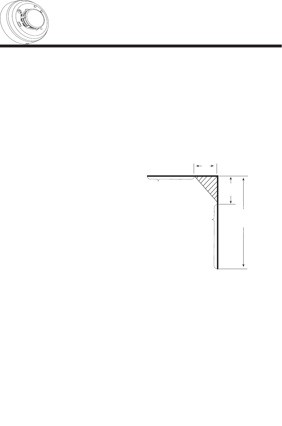
When wall-mounting, install smoke detectors so the
top edge of the unit is 4 to 12 inches below where
the wall and ceiling adjoin. See Figure 1.
Install smoke detectors in a suitable environment
that maintains a temperature between 32°F (0°C)
and 100°F (38°C) and humidity levels between 0
and 95% non-condensing.
Avoid mounting near air conditioners, heating
registers, and other ventilation sources that may
interfere with smoke entering the chamber.
•
•
•
•
•
•
•
•
•
•
•
•
When more than one detector is required, spacing of
30 feet (9.1m) may be used as a guide on ceilings.
Note: Consult NFPA 72, the local Authority Having
Jurisdiction (AHJ), and/or applicable codes for
specific information regarding the spacing and
placement of smoke detectors.
Avoid mounting near kitchens, wood stoves, garages,
furnaces, and bathrooms.
Mount all smoke alarms within 100 feet of the panel
or transceiver.
Install a smoke detector in the hallway outside of
each bedroom.
4 inches min.
12 inches
maximum
CEILING
Place top edge 4 to 12
inches below where
wall and ceiling adjoin.
WALL
4 inches min.
Mount detector at
least 4 inches away
from adjoining wall.
Figure 1: Smoke Detector Placement
Tamper-Resistant Feature
Each detector is equipped with a tamper-resistant feature
that prevents removal from the mounting base without
the use of a tool. To engage the tamper-resistant feature,
remove the small plastic tab located on the mounting base
(Figure 2). To remove the detector from the base once it
has been made tamper resistant, use a small screwdriver
to depress the square tamper release tab, located on the
skirt of the mounting base, and turn the detector coun-
terclockwise. Note: For installations where unauthorized
removal of the detector head is not a concern, the head
can be removed by simply turning counterclockwise.
•
•
•
•
1
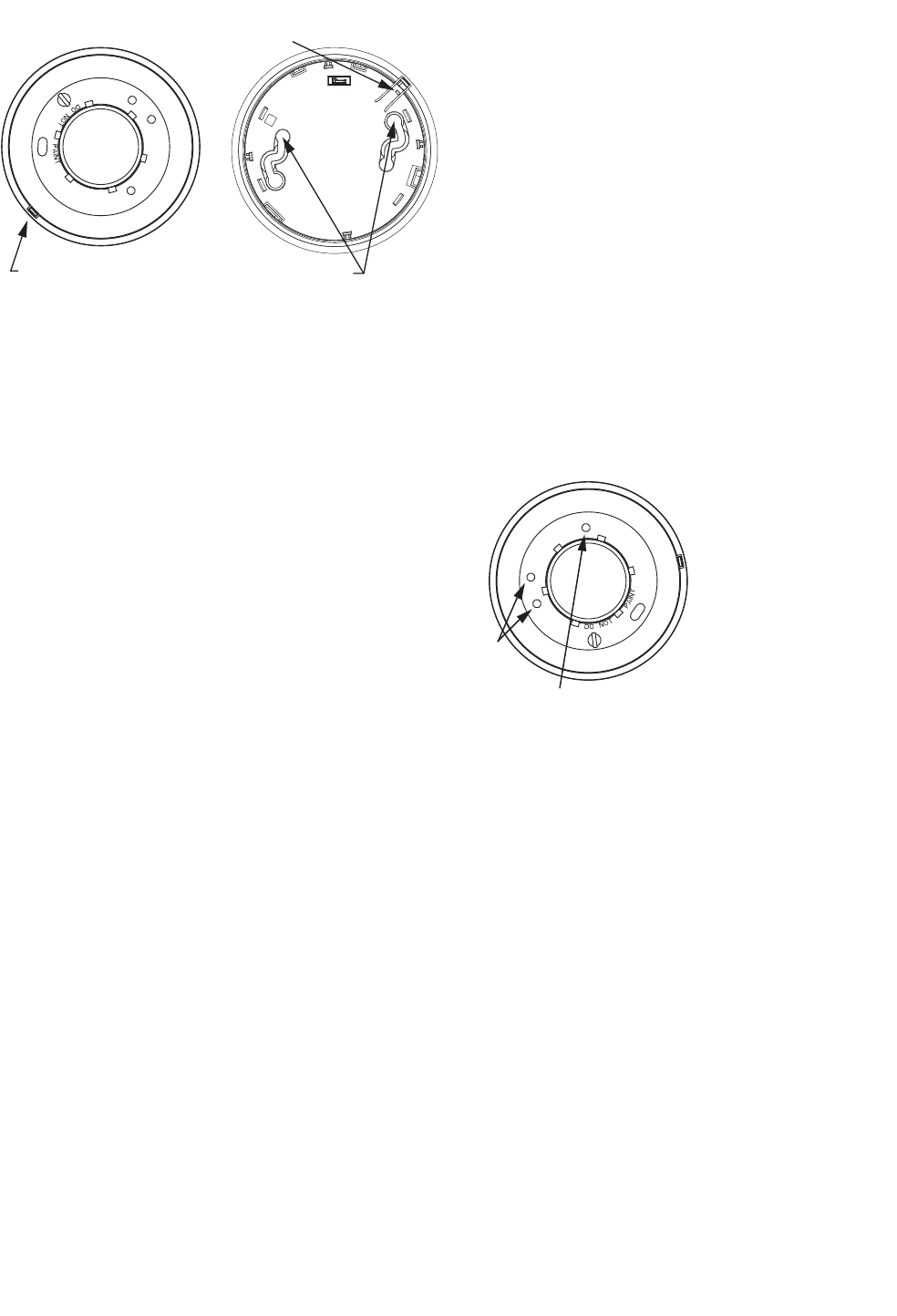
SNAP OFF TAB FOR
TAMPER LOCK
TAMPER RELEASE TAB MOUNTING HOLES
Figure 2: Tamper-Resistant Feature
Installing the Mounting Base
The mounting base can install directly to standard
single-gang electrical boxes, 4-inch square or octagonal
boxes, 3.5-inch octagonal boxes, or directly mounted to
a wall or ceiling using drywall fasteners.
Select a sensor location using applicable
requirements and the guidelines presented in the
Installation section of this manual.
Separate the mounting base from the unit by turning
the smoke detector counterclockwise.
Secure the mounting base to the desired surface. If
mounting onto plaster or dry wall, use appropriate
anchors.
Align the molded line on the base with the raised
marks on the smoke detector and turn clockwise to
lock in place.
To remove the smoke detector from the base, simply
twist counter-clockwise to unsnap.
Programming
The following instructions provide a guideline for pro-
gramming the SMK into system memory.
To enroll a SMK into system memory:
Enter program mode (NEXT + NEXT + NEXT +
<Prog> + Installer PIN)
The keypad will display “Devices Available.” Select
<Learn>. The display shows “Auto Enroll On.”
To enroll the SMK, insert a small screwdriver
or allen wrench (0.18˝ max.) into the test switch
opening; push and hold. Alternatively, activate
the alarm by using “Smoke! in a Can®” or direct
actual smoke into the smoke chamber until an alarm
occurs.
Upon enrollment, the keypad emits one beep and the
display shows the zone number and sensor ID.
Continue enrolling additional sensors if desired.
When finished, press <Done> to exit.
1.
2.
3.
4.
5.
1.
2.
3.
4.
5.
Testing
The following steps provide a general procedure for
testing the smoke detector.
Smoke Entry
Test the detector for smoke entry using one of the fol-
lowing methods:
Use “Smoke! in a Can®” and follow the directions
on the can.
Hold a smoldering punk or cotton wick close to
the unit and gently direct the smoke into the smoke
chamber for 20 seconds or until an alarm occurs.
Test Switch
An opening for the recessed test switch is located on
the detector housing (See Figure 4).
Insert a small screwdriver or allen wrench (0.18˝
max.) into the test switch opening; push and hold.
If the detector is within the listed sensitivity limits, the
detector’s red LED should light within one second.
LEDS
RECESSED TEST SWITCH
Figure 3 Recessed Test Switch
Walk Test
Press NEXT + NEXT and the keypad will display
LOG TEST RESET.
Select <Test> and enter the installer or user PIN.
The display will show WALK COMM.
Select <Walk> and the keypad will display “Walk
Test Active.”
Trip each zone/sensor one at a time and the system
responds with a tone from the keypad.
As each tested sensor is added to a scrolling list of
tested sensors, the signal strength will be shown on
the LCD display as 1-10. A higher value indicates
a stronger signal level. A minimum level of five is
recommended.
Exit walk test mode by pressing <Done>.
•
•
1.
2.
3.
1.
2.
3.
4.
5.
6.
2
Maintenance
Cleaning
Place the system in walk test mode.
Remove the detector from the base by turning
counter-clockwise.
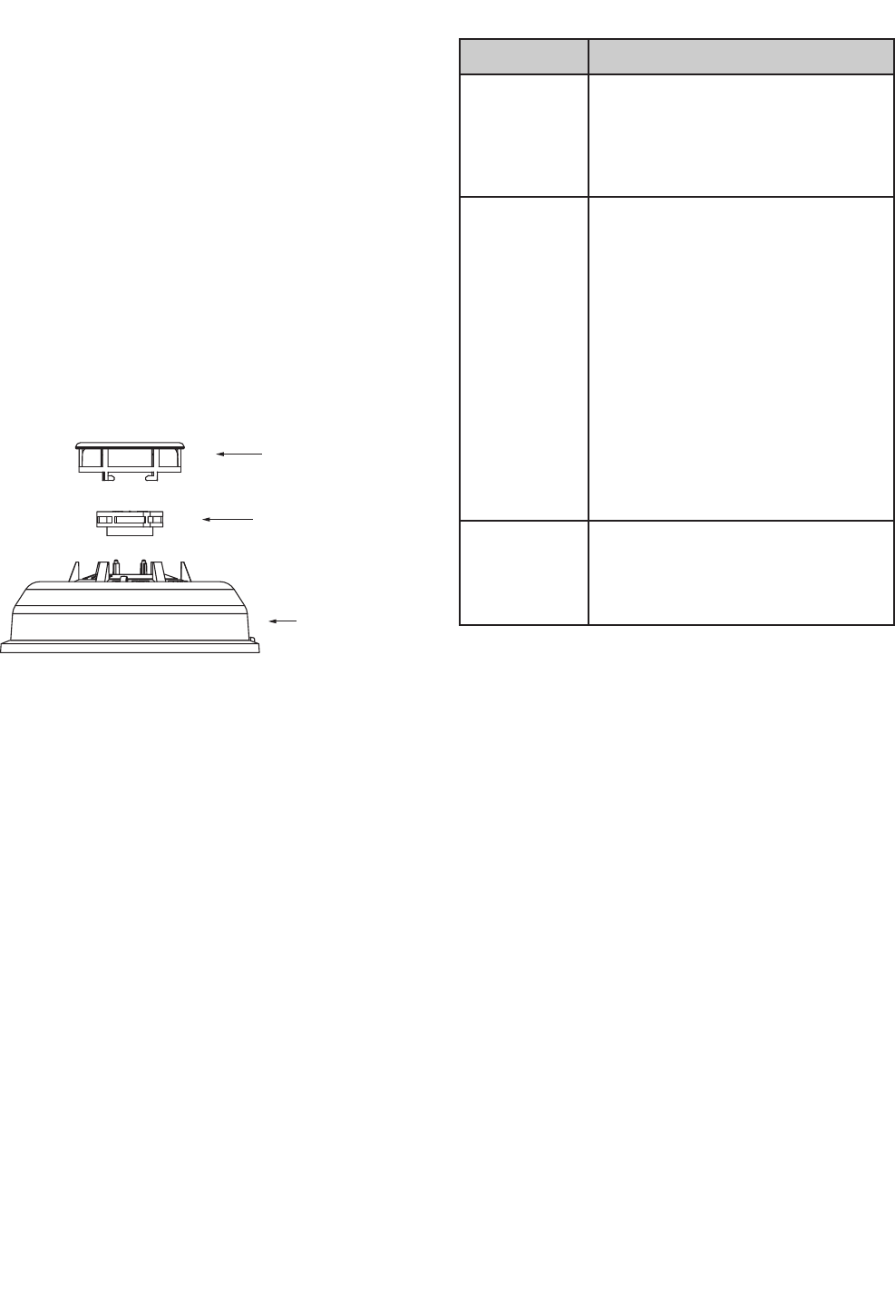
Remove the top half of the screen/sensing chamber
by lifting straight up (Figure 4).
Vacuum or use canned air to remove any dust or
particles that are present on both chamber halves.
Replace the top half of the screen/sensing chamber
by aligning the arrow on the screen/sensing chamber
with the arrow on the housing. Press down firmly
until the screen/sensing chamber is fully seated.
Replace the detector cover by placing it over the
screen/sensing chamber and turning it clockwise
until it snaps into place.
Reinstall the detector and test.
REMOVABLE DETECTOR COVER
SCREEN/SENSING CHAMBER
(TOP HALF)
DETECTOR HOUSING
Figure 4: Removing Screen/Sensing Chamber
Battery Replacement
Replace the battery when the smoke alarm or panel
notifies you that the battery is low. When the battery
needs to be replaced, the smoke detector transmits
a signal to the control panel. If the battery is not
replaced within 7 days, the unit will annunciate a
single beep approximately every 60 seconds.
Remove the smoke detector from the base and
remove the battery cover.
Observe correct polarity and insert the battery into
the battery holder.
1.
2.
3.
4.
5.
6.
7.
1.
2.
3.
Troubleshooting
Problem Action
The system
indicates a
sensor trouble
for a wireless
sensor.
A trouble is caused when the sensor
tamper switch is activated — i.e. the
sensor cover is off, not secured, or
the sensor is not mounted properly.
Secure the sensor over and trip sensor
to clear the trouble.
•
The panel does
not respond to
wireless sensors.
There are no
alarm, chime,
or walk test
responses.
Verify that the EXT is enrolled. This
can be done by checking option “EXT
Module” (60401) in the “ST - Modules”
menu in programming. If this option
is 0, the EXT is not recognized by the
system. Remove the EXT and see if a
trouble occurs. If not, replace the EXT.
Bring the wireless sensors closer to
the EXT and test again. If signals are
properly received, the issue may be
related to environmental noise or
interference.
Distance from the receiver and/or
installation environment will affect
the sensor signal strength. Reposition
the sensor and/or EXT if necessary.
•
•
•
The system
indicates a
sensor low
baery.
Replace the sensor’s battery. Test the
sensor after replacing the battery.
Testing the device allows the control
panel to receive a signal with the new
battery information.
•
3

Specifications
Compatibility: All Sequel Technologies ST Security
Systems (ST8 requires Expansion Transceiver Module)
Dimensions (including base): 5.3” x 2.0” (D x H)
Battery: 3.0V CR123A, Lithium battery (average
battery life is 3-5 years)
Diameter (including base): 5.3 inches
Height (including base): 2.0 inches
Sensitivity: 2.5%/ft. nominal
Sound Pressure Output: 85 dBA
Mounting:
3½-inch or 4-inch octagonal back box
Single gang back box
4-inch square back box with a plaster ring
Direct mount to ceiling
Transmitting Frequency: 319.5 MHz and 345 MHz
Supervision Interval: 60 minutes
Transmit Range: 500 feet, open air
Operating Temperature: 32° to 100°F (0° to 38°C)
Storage Temperature: – 4° to 158°F (– 20° to 70°C)
Max. Humidity: 90% relative humidity, non
condensing
Regulatory Approvals: FCC 15, UL (Pending)
FCC Notice
This device complies with Part 15 of the FCC Rules. Operation is subject to
the following two conditions: (1) this device may not cause harmful interfer-
ence, and (2) this device must accept any interference received, including
interference that may cause undesired operation. Changes and/or modica-
tions not approved by Sequel Technologies, LLC could void the user’s
authority to operate the equipment.
•
•
•
•
•
•
•
•
◦
◦
◦
◦
•
•
•
•
•
•
•
Sequel Technologies
2958 Cleveland Ave. N
Roseville, MN 55113 USA
Copyright © 2008 Sequel Technologies, LLC.
4