SercoNet WAP-80211B NetHome Wireless Access Point User Manual System Guide Users Manual
SercoNet Ltd. NetHome Wireless Access Point System Guide Users Manual
SercoNet >
Contents
- 1. System Guide Users Manual
- 2. WAP Users Guide
System Guide Users Manual

Revolutionizing Home Networking
SercoNet Smart Outlet™ Network
Technical User Guide
SRC-DOC10MAN11-2002
2
Table of Contents
1. INTRODUCTION ........................................................................4
1.1. THE SMART OUTLET™ NETWORK AND BENEFITS....................4
1.2. HOW THE SMART OUTLET™ NETWORK WORKS......................5
2. INSTALLATION .........................................................................7
2.1. WHAT’S IN THE BOX? .............................................................7
2.2. PRE-INSTALLATION..............................................................14
2.3. EQUIPMENT INSTALLATION ...................................................16
3. OPERATING THE SYSTEM ....................................................40
3.1. CABLE CONNECTION ...........................................................40
3.2. ETHERNET CONNECTION .....................................................40
3.3. NETWORK CONFIGURATION .................................................40
4. TESTING AND VERIFICATION...............................................41
4.1. VOICE TESTING PROCEDURE ...............................................41
4.2. DATA TESTING PROCEDURE ................................................41
4.3. ETHERNET TESTING HARDWARE – SMARTESTER ..................42
5. TROUBLESHOOTING .............................................................45
5.1. INSTALLATION TROUBLESHOOTING .......................................46
5.2. POST INSTALLATION TROUBLESHOOTING ..............................47
5.3. REPLACING UNITS ...............................................................49
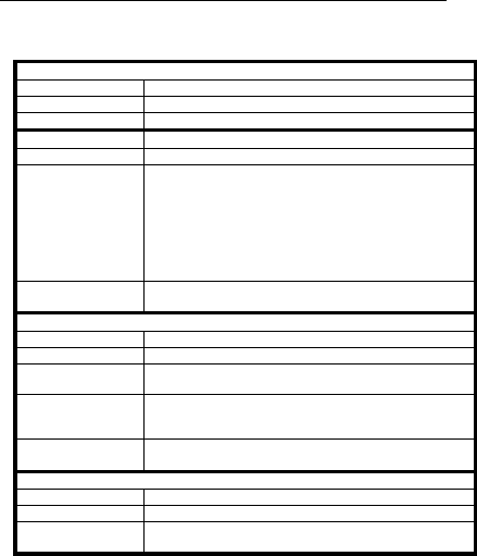
6. SPECIFICATIONS....................................................................51
6.1. SMART OUTLET™ ...............................................................51
6.2. POWER UNIT.......................................................................53
6.3. PRIMARY SMART OUTLETTM ADAPTOR..................................54
6.4. STARBOX ...........................................................................55
6.5. SMARTESTER ......................................................................56
6.6. SURFACE MOUNT ADAPTOR.................................................57
6.7. WALL MOUNT ADAPTOR ......................................................57
APPENDIXES 58
A. TOPOLOGIES ..........................................................................58
3
A.1. TYPICAL WIRING TOPOLOGIES .............................................58
A.2. TOPOLOGY TIPS..................................................................77
B. PRODUCT LIST AND ORDERING INFORMATION ...............78
C. PHONE AND DATA CABLING................................................80
D. QUICK NETWORKING GUIDE................................................81
D.1. WINDOWS 98™ ..................................................................81
D.2. WINDOWS 2000™ ..............................................................83
D.3. WINDOWS XP™..................................................................86
E. GLOSSARY OF HOME-NETWORKING TERMS....................93
F. FAQ 104
G. CUSTOMER SUPPORT.........................................................107
H. WARRANTY INFORMATION ................................................108
I. APPROVALS .........................................................................112
I.1. FCC / PART 15 COMPLIANCE STATEMENTS ......................112
I.2. FCC / PART 68 COMPLIANCE STATEMENTS ......................115
4
1. INTRODUCTION
1.1. The Smart Outlet™ Network and Benefits
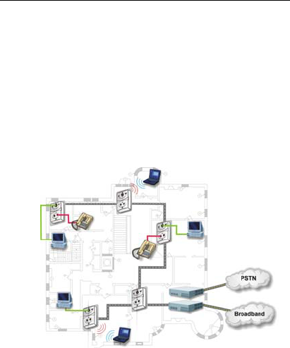
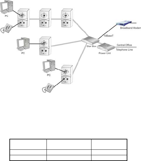
The SercoNet Smart Outlet™ network distributes residential and
SOHO broadband communication to devices such as PCs, printers
and scanners. The system uses existing phone wires to deliver free-
flowing, uninterrupted data, voice, and video streams at broadband
speeds. Simply replacing the home phone jacks with SercoNet Smart
Outlets™ automatically creates a home 10Mbps Ethernet LAN
backbone over the home phone wires. This new backbone
guarantees the Smart Outlet™ network’s high bandwidth and allows
the customer to run multimedia applications alongside data services.
In addition, customers need not worry about losing telephone
services, since the Smart Outlet™ network maintains intact Telephone
services during power outages.
Figure 1.1. SercoNet Smart Outlet™ Network Diagram

5
1.1.1 Flexible Interfacing
The Smart Outlet™ network features various physical interfaces to
connect multiple home device types without extra protocol or interface
converters. The Smart Outlet™ itself is endowed with the dominant
standard 10BaseT interface, enabling customers to directly connect
multiple home devices to the Smart Outlet™ network’s backbone.
Beyond 10BaseT, the Smart Outlet™ network supports other standard
interfaces like IEEE-802.11b, providing maximum device connectivity
and flexibility via interchangeable parts.
1.1.2 Broadband Service Providers’ Extended Reach
The Smart Outlet™ network suits a wide spectrum of customers:
• Home users desiring a smart-home.
• Installers seeking easy broadband provision.
• Broadband service providers wishing to sell new value-added
services over the Smart Outlet™ network.
The network’s house-wall demarcation point enables broadband
providers to redefine the border between the customer and service
provider domains. Thus, the Smart Outlet™ network integrates the
home broadband backbone with the provider’s service equipment.
This fusing of the home backbone with the broadband service
provider’s remote-controlled home-networked applications increases
customer loyalty and reduces customer churn.
Also, by using the SercoNet Smart Outlet™ network, broadband
service providers can provide maintenance and support for their
customers’ home networking services, a one-stop-shop transparency
that paying customers expect and value.
1.2. How the Smart Outlet™ Network Works
Implementing the No-New-Wires approach, SercoNet's Smart
Outlet™ broadband network makes home networking effortless,
requiring nothing more than a simple, fast replacement of standard
6
home phone jacks with Smart Outlets™. The easy-to-install Smart
Outlets™ serve as mini-repeaters: each Smart Outlet™ terminates
and regenerates network data and then transfers the data to the next
Smart Outlet™. The resulting network guarantees constant high-
speed data in every room of the customer’s home.

7
2. INSTALLATION
2.1. What’s in the box?
SercoNet’s Smart Outlet™ Installation Kit includes the following items
(the exact packing list may vary depending on system topology and
ordered equipment):
• Power Unit
• Smart Outlet
• StarBox
• Primary Smart Outlet™ Adaptor
• Surface Mount Adaptor
• Wall Mount Adaptor
• Outdoor Box for Smart Outlet™
• Smartester
• Additional Package Items
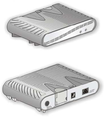
2.1.1 Power Unit
Catalog No: SRC-PWRU
Description: The Power Unit provides power to the Smart
Outlet™ network and prevents information based on data from
entering or exiting the house. One Power Unit is required for each
telephone line system.
8
Figure 2.1: SercoNet Power Unit – Front View
Figure 2.2: SercoNet Power Unit – Rear View
Additional Accessories for SRC-PWRU: Power cable
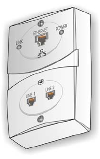
2.1.2 Smart Outlet™
Catalog No.: SRC-10MPS
Description: The SercoNet Smart Outlet™ enables
communication between data devices at 10Mbps over existing
phone wires while leaving the phone system operable. To form a
home network, at least two Smart Outlets™ are required (quantity
per order request).
9
Figure 2.3 SercoNet Smart Outlet™
10
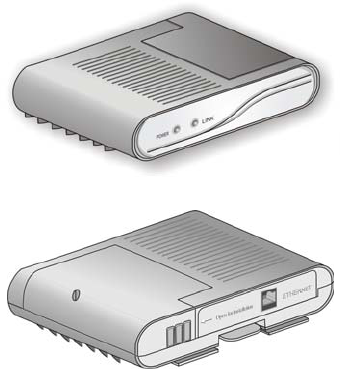
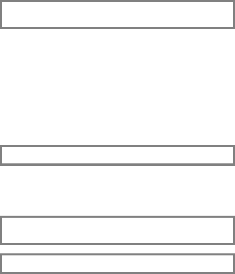
2.1.3 StarBox
Catalog No.: SRC-10STAR
Description: The StarBox is the central unit supporting star (home-
run) topology. The StarBox supports up to seven extensions for
10BaseT and one Ethernet 10BaseT port that can be used for
broadband connectivity (optional).
Figure 2.4: SercoNet StarBox – Front View
Figure 2.5: SercoNet StarBox – Rear View
11
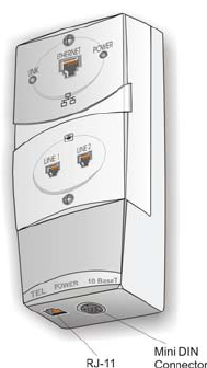
2.1.4 Primary Smart Outlet™ Adaptor
Catalog No.: SRC-10FRST
Description: The Primary Smart Outlet™ Adaptor enable
connection of SercoNet Power Unit and a direct Central Office
Telephone line in locations where there is no demarcation point or
suitable physical position to install the Power Unit. In addition, the
adaptor enables direct xDSL connection to the phone line system.
The adaptor includes mini DIN and Telephone RJ-11 connections
(optional).
Figure 2.6: Primary Smart Outlet™ Adaptor
12
2.1.5 Surface Mount Adaptor
Catalog No.: SRC-ADPROUN
Description: Adaptor plate per outlet for surface mount where
irregular phone jacks exist or round jacks (optional).
Figure 2.7: SercoNet Surface Adaptor
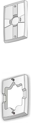
2.1.6 Wall Mount Adaptor
Catalog No.: SRC-ADPWMNT
Description: Adaptor plate for wall mount phones (optional).
Figure 2.8: SercoNet Wall Mount Adaptor
13
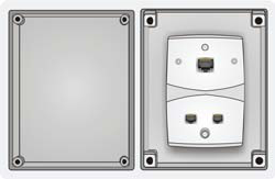
2.1.7 Outdoor Box for Smart Outlet™
Catalog No.: SRC-ADPOUTDOOR
Description: The adaptor for Smart Outlet™ outdoor installation
(optional).
Figure 2.9: SercoNet Outdoor Box
2.1.8 Smartester
Catalog No.: SRC-MINITST
Description: Smartester is an easy to use installer’s tool for data
transmission, error detection and telephone line existence testing,
diagnostics and verification during and after the Smart Outlet™
network installation (optional – quantity per order request).

14
Figure 2.10: SercoNet Smartester
2.2. Pre-Installation
Prior to starting your Smart Outlet™ installation, it is recommended to
match the home wiring topology with one of the following typical wiring
topologies (for further topology options and variations, please see
Appendix A – ‘Topologies’).
2.2.1 Determining Phone Wiring Topology
Determine whether the demarcation point (the Central Office
Telephone line connection) is inside or outside the home. Also, check
the home’s phone-wiring topology: Is it daisy-chained, Star (Home-
Run), or a hybrid of the two topologies?
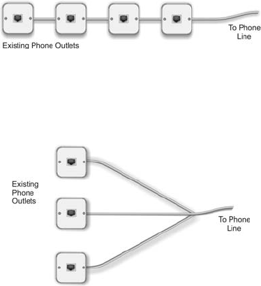
2.2.1.1. Daisy-Chain Topology
Most homes have daisy-chain phone-wiring topology. That means
that the first outlet is connected directly to the demarcation point while
the remaining outlets are connected in series. (See Figure 2.11 below
for an example of a daisy-chain topology).
15
Figure 2.11: Daisy-Chain Topology
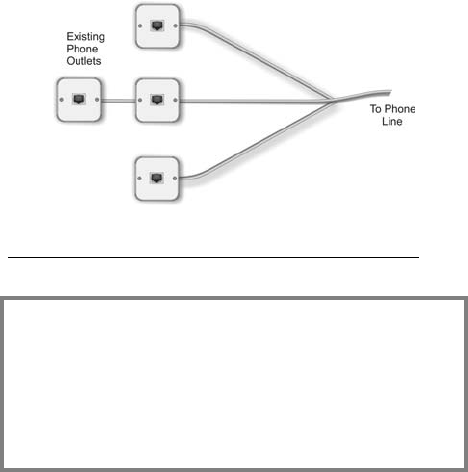
2.2.1.2. Star (Home-Run) Topology
Some new homes have Star phone wiring topology (also known as
Home-Run topology). In such cases, each outlet connects directly
with the demarcation point without going through any other outlets
(see Figure 2.12, below, for Star (Home-Run) topology illustration).
Figure 2.12: Star (Home-Run) Topology
2.2.1.3. Hybrid Daisy-Chain/Star Topology
In some homes, Star (Home-Run) and daisy-chain topologies are
combined so that some outlets are directly connected to the
demarcation point, while others are connected indirectly through other
outlets.
16
Figure 2.13: Hybrid Daisy-Chain/Star Topology
2.3. Equipment Installation
Attention!
a. Old telephone wires may be susceptible to
corrosion. For quality connections, rub off any
rust or corrosion using sandpaper.
b. Installation of the SercoNet network is simple, and
requires minimal tools. In most cases, a
screwdriver, a wire-stripper or cutter and a dial
tone detector are all you need for installation.
2.3.1 Power Unit and Smart Outlets™
Identify a suitable location to position the Power Unit. It can be wall-
mounted or placed on a clean, stable desktop.
17
2.3.1.1. Installing the Power Unit
Note: For various Power Unit installations topology options
beyond what is described in the following paragraph refer to
Appendix A – ‘Topologies’.
If the demarcation point is inside your home, such as in the basement,
then the Power Unit should be installed near the demarcation point.
The Power Unit can be installed anywhere on your existing telephone
cable and the Smart Outlet™ network will start from this point and into
the house. Another option is to connect the Power Unit to the Primary
Smart Outlet™ point (see Installing the Primary Smart Outlet™
Adaptor on page 26). Also, the Power Unit should be located within a
short distance of the phone wiring and an AC-mains plug outlet. When
dealing with Star (Home-Run) topology, make sure that the location
you have selected is suitable for both the Power Unit and the StarBox.
2.3.1.2. Power Unit Connections
Note: Perform Step 1 only in the case that the Power Unit is
connected to the Primary Smart Outlet™ Adaptor.
Step 1 Connect one end of the 6 ft. Mini-DIN cable, supplied with
the Primary Smart Outlet™ adaptor between the Power Unit
rear panel mini DIN connector marked as “Special Adaptor”
and the Primary Smart Outlet™ Adaptor DIN connector.
CAUTION: Do not plug the power cable into the AC main power
outlet until all necessary phone outlets have been replaced with
Smart Outlets™.
Note: Perform Steps 2 and 3 only in the case that there is a direct
connection between the Central Office line and the Power Unit.
18
Step 2 Connect the Central Office line to the assigned RJ-11 jack
or terminal block as shown in Figures 2.14 and 2.15.
Step 3 Connect the closest Smart Outlet™ using phone wires to
the assigned terminal block.
Figure 2.14: Power Unit Rear Panel
Figure 2.15: Power Unit Wiring
CAUTION: Do not plug the power cable into the AC main power
outlet until all necessary phone outlets have been replaced with
Smart Outlets™.
19
Notes:
1. The maximum current that can be consumed from the SRC-
POWERU’s (Power Unit’s) Terminal Block marked as “Outlet” is
0.9 ADC.
2. The limitation of this current is achieved by an Overload
Current Protection Circuitry installed in the SRC-POWERU
(Power Unit).
Step 4 Connect the remaining Smart Outlets™, as described in
Section 2.3.1.3.
Step 5 Plug the power cable to the AC mains power outlet.
Step 6 Check the Power Unit LED indicators.
Figure 2.16. SercoNet Power Unit Front Panel

20
LED
STATE
POWER LINE
PU off - -
Power Unit initialization process – up to 8 sec
(flashing with 1 sec period)
Yellow Yellow
Normal Operating State Green Green
PU circuits failure Red Yellow
CO is not connected Green Yellow
Line feeding problem (might be short circuited) Yellow Red
Start-up problem (might be high capacity line
load).
Red Red
Table 2.1: Power Unit LEDs
After approximately one minute, when the Power Unit finishes a self-
testing cycle, the front panel ‘POWER’ LED should light-up green to
indicate that the Power Unit is functional. Should the Power Unit front
panel ‘POWER’ LED light up red, then the self-test has failed. This
could be due to a Power Unit fault or short-circuit along the phone
wiring: In this case, disconnect the Power and refer to
TROUBLESHOOTING on page 49. Should the Power Unit front panel
POWER LED light up red; this indicates that a problem occurred
following the startup sequence.
For further information on LED functionality, please refer to table 2.1.
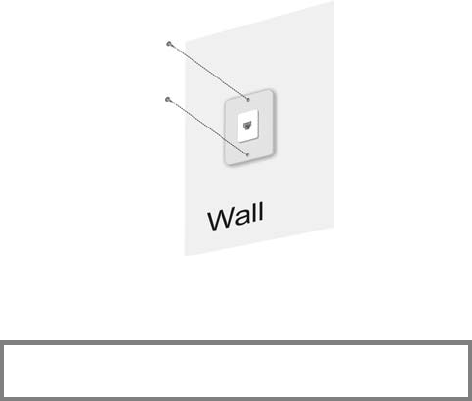
2.3.1.3. Installing Smart Outlets™
The Smart Outlet™ system requires the replacement of all phone
outlets located along the phone-wiring segment used for home
networking. If you are not entirely familiar with home phone wiring
topology, it is recommended that you replace all the existing phone
outlets with the Smart Outlets™. To replace the existing phone
outlets with Smart Outlets™ do the following:
21
Step 1 Remove necessary existing phone jacks as shown in Figure
2.17.
Figure 2.17: Phone jack removal
Step 2 Disconnect the wiring at the rear of the phone jack and put
the old phone jack aside. Make sure to keep track of the
phone wire pairs.
Note: The telephone wire connections are made on the terminal
blocks at the rear of the Smart Outlet™, as shown in Figures 2.18
and 2.19.
22
Figure 2.18: Smart Outlet™ Rear Panel
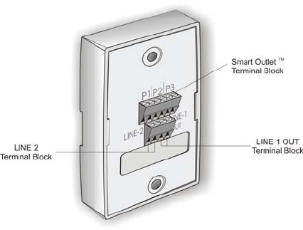
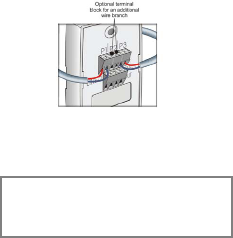
Step 3 Connect the telephone wires on the terminal block at the
rear of the Smart Outlet™ as shown in Figure 2.19,
locations P1, P2, or P3. Loosen the screw of each terminal,
and then insert the wire into the corresponding slot. Fasten
the screw to hold the wire in place.
23
Figure 2.19: Wiring the Smart Outlet™
The Smart Outlet™ connector has an additional two-wire terminal
block for an additional branch connection, as shown in Figure 2.19,
above.
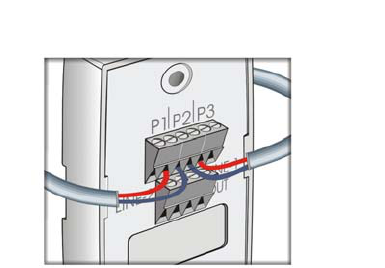
Note: Make sure to keep wire pairs juxtaposed. The sequence of
wire pairs within the terminal block is not important. In rare
cases, some phone sets are polarity sensitive. (If for some
reason, the phone set does not function; try switching the wires
within each pair). Connect the wires starting from the left or right
end of the connector. See Figure 2.20 below for an illustration of
incorrect wiring installation.
24
Figure 2.20: Incorrect Wiring Connection
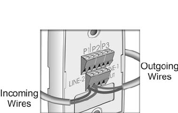
Step 4 Connecting a second phone line is done using the Line 2
connection. The second phone line incoming wires must be
shorted to the outgoing wires using the same terminal block
connections, as shown in Figure 2.21.
25
Figure 2.21: Terminal Block second line connector
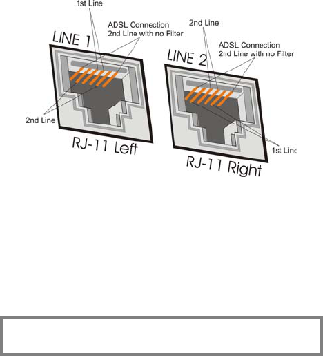
The internal wiring of each outlet is that P1-P3 and “LINE-1
OUT” terminal blocks on the back panel are connected to
RJ-11 right (LINE 2) pins 2 and 5, and RJ-11 left (LINE 1)
pins 3 and 4. “LINE-2” terminal block on the back panel is
connected to RJ-11 right (LINE 2) pins 3 and 4 and PJ-11
left (LINE 1) pins 2 and 5, as shown in Figure 2.22.
26
Figure 2.22: RJ-11 Connector Pins
Step 5 In cases where only a portion of the house is installed with
the Smart Outlet™ network, it is possible to terminate the
system and continue only with a telephony system, without
needing to replace additional phone jacks. In this case,
connect the outgoing wires to the LINE-1 OUT terminal
block at the back of the Smart Outlet™.
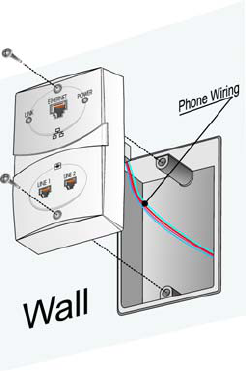
Step 6 Fasten the Smart Outlet™ to the back plate using the
screws provided by SercoNet, as shown in Figure 2.23.
Note: It is important that no standard phone outlets exist along
the phone-wiring segment between SercoNet outlets. Phones
plugged in these outlets could sustain damage.
27
Figure 2.23: Mounting the Smart Outlet™ onto a standard
phone jack
Step 7 After installing all relevant Smart Outlets™, power up the
system.
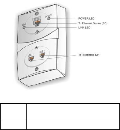
Step 8 Check the Smart Outlet™ LED indicators. (See Figure
2.24).
Each Smart Outlet™ includes LEDs indicating the functional
status of the Smart Outlet™, as shown in Table 2.2.
28
Figure 2.24: SercoNet Smart Outlet™ Front Panel
LINK
(yellow)
Lights steadily ON or blinks when the data
equipment connected to the Smart Outlet™
is communicating on the network.
POWER
(green)
Lights steadily ON when the Power Unit is
supplying power to the Smart Outlet™.
Table 2.2 Smart Outlet™ LEDs
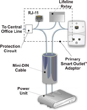
2.3.2 Installing the Primary Smart Outlet™ Adaptor
The Primary Smart Outlet™ Adaptor is assembled together with the
SercoNet Smart Outlet™, as shown in Figure 2.26. It includes a mini
DIN and one Telephone RJ-11 connectors. The mini DIN is used for
connection to the Power Unit (cable supplied with the product). This
cable is 6 feet long and is direct-wired pin-to-pin (i.e., pin 1 on one end

29
is shorted to pin 1 on the other end). Connecting the Power Unit to
the Primary Smart Outlet™ Adaptor enables power feeding of a
complete SercoNet Smart Outlet™ network (see Figure 2.25 below).
The telephone RJ-11 connector connects ADSL modems directly to
the Central Office lines.
In addition, the Primary Smart Outlet™ Adaptor provides protection
against power spikes coming from the telephone central office.
In case the connection between the Power Unit and the Primary Smart
Outlet™ Adaptor is disconnected, the C.O. line is connected directly to
the home wiring, preserving life line emergency telephone services.
Attention!!
When using the Primary Smart Outlet™ Adaptor, the Central
Office must be connected to the Primary Smart Outlet™ Adaptor
and not directly to the Power Unit Central office connector.
Connecting the Central Office directly to the Power Unit will
cause the lifeline to become lost in case of a power outage.
30
Figure 2.25: Primary Smart Outlet™ Adaptor Block Diagram
To install the Primary Smart Outlet™ Adaptor:
Step 1 Remove the current phone jack faceplate.
Step 2 Disconnect the wires attached to the phone jack.
Step 3 Locate and identify the Central Office telephone line wire
pair that enters the home by listening for a dial tone with a
phone set.
Step 4 Connect the Central Office Line wire pair to the Primary
Smart Outlet™ Adaptor connection marked C.O. (Central
Office Line) (Figure 2.26 & 2.27).
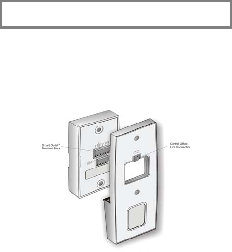
31
Step 5 Connect the wire pair that goes into the next phone outlet to
one of the rear connections marked P1, P2, or P3 (Figure
2.26 & 2.27).
Note: In rare cases, some phone sets are polarity sensitive. If the
phone set does not function as before the installation, change
the wire polarity within each pair.
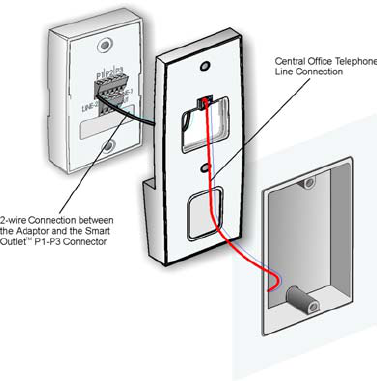
Step 6 Using the attached wires, connect the Primary Smart
Outlet™ Adaptor to the Smart Outlet™ assembled on top of
the device.
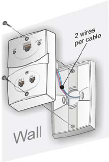
Step 7 Attach the Primary Smart Outlet™ Adaptor together with the
Smart Outlet™ to the wall instead of the phone faceplate, by
using the faceplate screws provided by SercoNet (see figure
2.27).
Step 8 Using the mini DIN cable, connect the Primary Smart
Outlet™ Adaptor to the Power Unit.
Figure 2.26: Rear Panel of Primary Smart Outlet™ Adaptor
32
Figure 2.27: Mounting Primary Smart Outlet™ Adaptor
2.3.3 Installing a StarBox
Typically, most homes possess a daisy-chain topology. However,
recent years have witnessed an increasing number of new homes built
with Star (Home-Run) topology phone wiring. These latter topologies
require use of the StarBox (see StarBox, section 2.1.3). If you need to
install a StarBox, make sure that the location you have selected is
suitable for both the Power Unit and the StarBox.
33
The rear panel of the StarBox includes an opening for connecting
multiple phone line branches that go to different locations in the home.
Install SercoNet Smart Outlets™ only in each phone wire branch that
you would like to connect to the network, as shown in Figure 2.28 and
2.29 below.
The Central Office phone line is connected to the SercoNet Power
Unit. Terminal block connectors located in the StarBox allow
connection to one or two Power Units and to multiple phone line
extensions (not to be confused with the PBX, please see Appendix
A – ‘Topologies’).
An additional Ethernet connector located at the StarBox rear panel
allows direct Broadband modem connection.
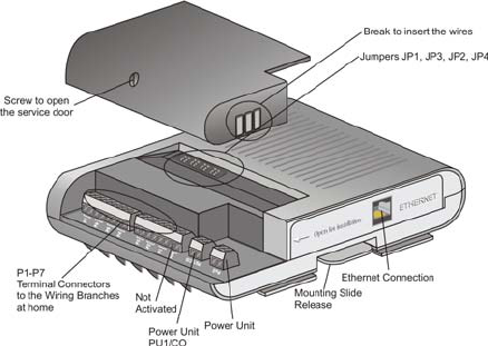
Figure 2.28: StarBox Connections
34
Figure 2.29: StarBox Configuration with Smart Outlets™,
Broadband Modem, Power Unit, and Accessories
The StarBox enables connection to two Power Units, allowing the
Smart Outlet™ system to run on two different phone line systems.
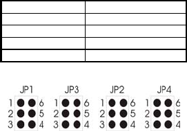
Internal jumpers (JP1-JP4) enable selection of four out of seven
branches (P4-P7) to operate over one of the two possible phone
systems, as described in Tables 2.3 and 2.4.
Power Unit
Connection
Jumper Positions Note
PU1/CO 2-3; 4-5 Default setting
PU2 1-2; 5-6
Table 2.3 StarBox Jumper Settings for the Power Units
35
Port Jumper Group
P7 JP1
P6 JP2
P5 JP3
P4 JP4
Table 2.4 StarBox Jumper Settings for the Smart OutletsTM
Figure 2.30: StarBox Jumpers
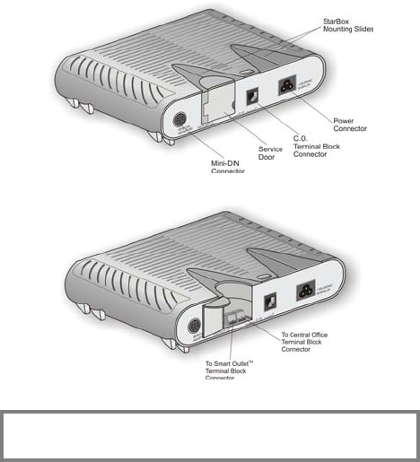
To install the StarBox:
Step 1 Open the StarBox cover by removing the service door
screw.
Step 2 Connect the phone wires to the appropriate terminal blocks
P1-P7.
Step 3 Connect using a pair of phone wires between the StarBox
terminal block marked “PU1” the Power Unit. In case that a
second Power Unit is required, use additional pair of phone
wires for connecting between the StarBox terminal block
marked “PU2” and the second Power Unit.
Step 4 In case of two Power Unit, select between the two phone
systems for branches 4-7 using JP1-JP4.
Step 5 Secure the wires to the binding post with a tiewrap.
Step 6 Close the top cover.
Step 7 Connect the broadband modem to the Ethernet port (if
applicable).
Step 8 Attached the StarBox to the Power Unit as described below.
Step 9 Replace the phone jacks at the remote side of the phone
wire with SercoNet Smart Outlets™.
Step 10 Connect the Power Unit to the AC power mains.

36
CAUTION: The connection to the AC power must be the last step
taken when installing a system. Any changes in the wiring
require that you first disconnect the power cord from the Power
Unit and return it only after the installation is complete.
To attach the StarBox to the Power Unit:
1. Align the front of the StarBox with the rear panel of the Power
Unit.
2. Slide the StarBox towards the front of the Power Unit until it
clicks into place.
To remove the StarBox from the Power Unit:
1. Lift the flap on the lower middle rear panel of the StarBox
towards the StarBox.
2. Slide the StarBox towards the rear of the Power Unit.
To install the StarBox on a table top or wall:
1. Unscrew the four screws holding the mounting slides to the
bottom of the StarBox.
2. Remove the mounting slides from the StarBox and place on a
tabletop or attach to the wall using the wall mount holes at the
bottom of the StarBox.
2.3.4 Mounting and Installation with Special
Mechanical Adaptors
2.3.4.1. Surface mount adaptor
Occasionally, a phone jack is physically incompatible with the Smart
Outlet™ or is non-standard. For this reason, SercoNet provides
adaptors for surface mounting these particular situations (see Figure
2.31).
Use of the adaptors may be for any of the following reasons:
37
• In case that there is no phone jack.
• In case of an existing round phone jack.
• For low cost wiring instead of Primary Smart Outlet™ Adaptor.
The Outlet Adaptor allows you to install the Smart Outlets™ on non-
standard phone jacks (see Figure 2.31).
Figure 2.31: Mounting the Smart Outlet™ with the Surface
Outlet Adaptor
38
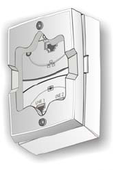
2.3.4.2. Wall Mount Adaptor
In some cases, it is required to replace a phone jack where there is a
wall mount phone attached. In theses cases, the Wall Mount Adaptor
enables replacing the phone jack with the Smart Outlet™ while
keeping the wall mount phone operational and mounted on top of the
outlet.
Figure 2.32: Mounting the Smart Outlet™ with the Wall
Mount Adaptor
2.3.5 Connecting Broadband (xDSL and Cable
Modem) to the Smart Outlet™ Network
Homes with Broadband Internet (xDSL, Cable modem, Residential
Gateway, ISDN Router, or WLL) are becoming increasingly common
worldwide. The SercoNet Smart Outlet™ network offers an ideal
solution for connecting an entire home with Fast Internet. There are
several installation scenarios that can be implemented using a Smart
Outlet™ network. The section below describes a general broadband
topology. For further topology scenarios, see Appendix A, Topologies.
39
Note: In many cases, a Ethernet cross-over cable is required for
connecting a broadband modem to the Smart Outlet™
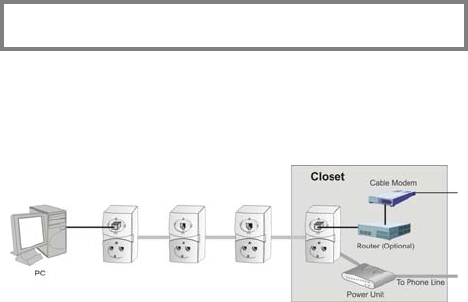
2.3.5.1. Two-Wire Home Infrastructure
If the broadband modem is connected at the home entrance to the
closest Smart Outlet™, then the broadband signal is terminated at the
home entrance, and the SercoNet transmission continues from that
point onward, inside the home.
Figure 2.33: Example of Basic 2-Wire Daisy-Chain
Broadband Topology.
2.3.5.2. Four-wire home infrastructure
Some home wiring is installed using four (4) or more wires. In these
cases, one pair can be used for carrying the voice and SercoNet
signals, while the other pair can carry ADSL or similar transmissions.
If the home possesses at least a 4-wire infrastructure, the topology
has greater flexibility for voice, data, and broadband communications.
Refer to Appendix A, Topologies, for an illustration of the various four-
wire connection scenarios.

40
3. OPERATING THE SYSTEM
After assembling all Smart Outlets™ and wiring the Power Unit,
initialize the network as follows:
3.1. Cable Connection
Connect a telephone set to the LINE1 or LINE2 port of each Smart
Outlet™ unit. Verify that a dial tone is activated on the proper
connector. For a two-wire home, dial tone will only exist on LINE1
connector.
3.2. Ethernet Connection
Connect the 10BaseT cable to the network devices at one end and to
the Smart Outlets™ at the other end. Usually, when connecting a
broadband modem, a cross Ethernet CAT5 cable is used. In the
remaining cases, a straight pin-to-pin Ethernet CAT5 cable is used.
CAUTION: Verify that no standard phone jacks exist on segments
between Smart Outlets™ prior to powering on the Power Unit.
Attempting to power a network with mixed outlet types (Smart Outlets™
and standard outlets) can result in damage to telephones connected to
the network and degrade the Ethernet network throughput.
3.3. Network Configuration
In order to enjoy Internet sharing and communication between data
services within the home, all devices must be configured to work in a
home networking environment. For networking tips, please refer to
Appendix D.

41
4. TESTING AND VERIFICATION
4.1. Voice Testing Procedure
Step 1 With the AC power disconnected from the Power Unit,
connect the phones to the Smart Outlets™.
Step 2 Check that you can hear clear dial tone from all the outlets
in the house.
Step 3 Dial the house telephone and make sure that all phones
ring.
Step 4 Dial from the house and make sure that you can
successfully place a call, and the voice is clear.
Step 5 If you have Caller ID, an answering machine or
speakerphones, please verify that they work properly.
Step 6 Connect the AC power to the Power Unit. Repeat all of the
above steps.
4.2. Data Testing Procedure
Step 1 After completing the SercoNet Smart Outlet™ network
installation, plug the Power Unit AC power cable to the main
power source.
Step 2 Verify that the telephone system is working at every outlet
by plugging in a phone at each location and listen for dial
tone.
Step 3 In case you have a SercoNet Smartester, check for data
(Optional) integrity on each Smart Outlet™ (see Ethernet Testing,
section 4.3.).
Step 4:
a. Verify that the PCs’ networking configuration is set
correctly to work in a home-networking environment
(see Appendix D, Networking Tips).
42
b. Connect the PC’s and other data devices to the Smart
Outlets™ using a CAT-5 straight cable.
c. Verify that the Link LED is lit. If the LED is not lit,
please refer to Troubleshooting, Section 5.
d. Verify that there is data streaming between the data
devices; if not, see Troubleshooting, Section 5.
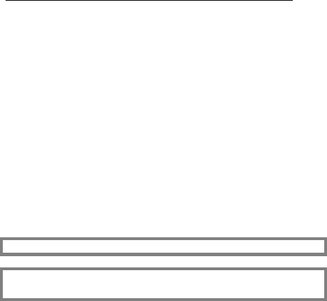
4.3. Ethernet Testing Hardware – Smartester
4.3.1 Smartester Description
The Smartester (Figure 4.2) is a SercoNet designed diagnostic tool
intended for the installer to test the SercoNet Smart Outlet™ network
once it is installed in the home. In addition to its ability to verify error-
free data transmission, the Smartester has the ability to detect phone
availability on line 1 and line 2. The tester is a compact and easy-to-
operate unit, connected to the SercoNet Smart Outlet™ using CAT5
Ethernet cables.
The on-site data testing uses a single device set to Transmitter mode
and one or more devices set to Receiver mode. The Transmitter
periodically broadcasts a packet to the Ethernet media and the
Receivers detect this packet and verify that its content is valid
(0xFFFFFFFFFFFF is set to be the MAC destination address).
The Smartester can be powered by internal 9V DC battery.
Note: The battery operation lifespan is limited.
Note: In order to change the operating mode, first turn the
Smartester off.
The Smartester has two RJ-45 connectors:
• Direct Ethernet connection (PC)
43
• Cross-over Ethernet connection (broadband modem or hub)
Figure 4.2: Smartester
4.3.2 Transmitter Operation
1. Connect the Smartester using one of the two RJ-45
connectors. The ACT LED should light green.
2. Each time the Transmitter sends a packet, the green
ACT LED located on the front panel (part of the RJ-45
connector) flashes yellow.
4.3.3 Receiver Operation
1. The Receiver constantly monitors for packets coming
from the network.
2. Each time a packet is received, the ACT LED located
on the front panel (part of the RJ-45 connector)
flashes yellow.
3. If a CRC error occurred in the last 15-second
operating interval, the FAIL LED lights red for 15
seconds.

44
4. If no CRC errors were indicated during the last 15-
second operating interval, the PASS LED lights green
for 15 seconds.
LED Color Functionality
STATUS Green Flashes once every second for one second while
power is ON.
STATUS Red Indicates low battery or internal error.
PASS/FAIL Green Solid green in Rx Mode if no errors were detected.
PASS/FAIL Red Solid red in Rx Mode if errors were detected in
15 sec time interval.
ACT Green Indicates “LINK” status.
ACT Red Flashes when packets are received or transmitted.
Table 4.1 Smartester LEDs
Switch Functionality
ON/OFF Power ON/OFF for the Smartester
Tx/Rx Selects Tx or Rx mode for the Smartester
Table 4.2: Smartester Switches
45
5. TROUBLESHOOTING

46
5.1. Installation Troubleshooting
5.1.1 Determining Home Wiring Topology
a. Identify the location where the telephone line enters the
house (location of NID). The most common location is
near the power entrance.
b. If there is a split of many wire-pairs leading from this
point, then the topology is Star (Home-Run).
c. If only one pair of wires originates from this point, then the
topology is daisy-chain.
Note: The house wiring topology has many variations. It is
recommended the installer understand the wiring topology of the
house before proceeding.
5.1.2 My outlets do not physically fit the Smart
Outlets™.
SercoNet has specific mechanical adaptors for different outlet
situations:
a. Wall mounting
b. Surface and round mounting
For details, please see sections 2.3.4.1 and 2.3.4.2.
5.1.3 I cannot determine the Primary Smart Outlet™
Adaptor location:
The primary Smart Outlet™ Adaptor should be located in place of the
first phone outlet where the SercoNet network begins. Therefore, the
Adaptor should be located at a desired place where the home

47
networking system starts and within reach of the SercoNet Power
Unit.
5.2. Post Installation Troubleshooting
5.2.1 The phone is working, but there is no data
transfer:
a. Check if the power is connected properly to the SercoNet
Power Unit and from the SercoNet Power Unit to the
Smart Outlets™ by checking that all POWER LEDs are lit.
b. Check the network device connections to the Smart
Outlets™.
c. Verify that the LINK LEDs on the Smart Outlets™ are lit.
d. Check the network configuration on the computer.
e. Connect the computer directly to the CPE (xDSL, Cable
Modem, Residential Gateway, other) and verify the
connection when bypassing the SercoNet system.
f. Replace the Smart Outlet™.
5.2.2 The data rate is very slow.
There are three possible reasons for slow data rate:
a. Another user on the same subnet is overloading the
network.
b. There may be Internet connection problems to the home.
Check with the Internet service provider.
c. The devices are connected by USB or wireless interfaces.
These interfaces are inherently slower than Ethernet IEEE
802.3 interfaces.

48
5.2.3 POWER LED on the SercoNet Smart Outlet™ is
not lit:
The POWER LED indicates whether power is being provided to the
Smart Outlet™. There are three possible variations of unlit POWER
LEDs:
a. POWER LED on all the Smart Outlets™ not lit: Verify that
there is no short circuit over the phone wires and that
there is a proper connection to the SercoNet Power Unit.
Verify that there is a suitable AC main power provisioning
to the PC.
b. Some POWER LED Smart Outlets™ are lit, some are not:
Check the phone wiring connections to the outlets that are
not lit.
c. Only one Smart Outlet™’s POWER LED is not lit: If
properly wired, replace the Smart Outlet™ with another.
5.2.4 LINK LED on the SercoNet Smart Outlet™ is
not lit:
The ‘LINK’ LED indicates the existence of an Ethernet connection
between the Smart Outlet™ and the network device (computer,
printer, xDSL modem, cable modem, etc).
a. Check that the computer is turned on (the computer must be
turned on for the LINK LED to be on).
b. Check the Ethernet cable connection between the network
device and the Smart Outlet™.
c. If possible, try to connect the computer and the cable to
another Smart Outlet™.
Note: In some cases there is a need for an Ethernet cross-over
cable.

49
5.2.5 LINE and POWER LEDs on the SercoNet Power
Unit show varying colors:
Table 2.1: Power Unit LEDs on page 20 can assists you in
pinpointing faulty conditions using the POWER and LINE LEDs of the
Power Unit.
5.2.6 POWER LED on the StarBox is not lit:
The POWER LED indicates when power is being transferred to the
StarBox.
a. If all the Smart Outlets™ are NOT lit: Check the SercoNet
Power Unit power connection and the connection
between the StarBox and the SercoNet Power Unit.
b. Only StarBox POWER LED is not lit: Replace the StarBox
with another.
5.3. Replacing Units
5.3.1 Replacing a Faulty Smart Outlet™:
a. Disconnect the SercoNet Power Unit.
b. Unscrew the Smart Outlet™ mounting screws.
c. Remove the faulty Smart Outlet™.
d. Taking note where each wire was connected, disconnect
the phone wires.
e. Reconnect the wires to the new outlet.
f. Reattach the Smart Outlet™ to the wall with the two
screws.
g. Reconnect the SercoNet Power Unit.
h. Verify dial tone and data transmission.
5.3.2 Replacing a Faulty Power Unit:
a. Disconnect power from the SercoNet Power Unit.

50
b. Disconnect the Smart Outlet™ system and the C.O.
connection from the SercoNet Power Unit.
c. Replace the SercoNet Power Unit.
d. Reconnect the Smart Outlet™ system and the C.O.
connection.
e. Reconnect the power to the SercoNet Power Unit.
f. Verify dial tone and data transmission.
Warning: When disconnecting the C.O. phone wires, the phone
system is not functional, including emergency calls.
5.3.3 Replacing a Faulty StarBox:
a. Disconnect the power from the SercoNet Power Unit.
b. Disconnect the broadband modem from the Ethernet
connector (if applicable).
c. If mounted to a Power Unit, physically disconnect the
StarBox from the Power Unit.
d. Lift the StarBox cover.
e. Taking note where each wire was connected and jumpers
selection, disconnect all the phone line extensions.
f. Reconnect all the phone line extensions to the new
StarBox.
g. If two Power Units are installed, set the phone system
selection jumpers.
h. Reconnect the SercoNet Power Unit to the new StarBox.
i. Close the new StarBox cover.
j. Reconnect the broadband modem to the Ethernet
connector (if applicable).
k. Reconnect the power to the SercoNet Power Unit.
l. Verify dial tone and data transmission.
51
6. SPECIFICATIONS
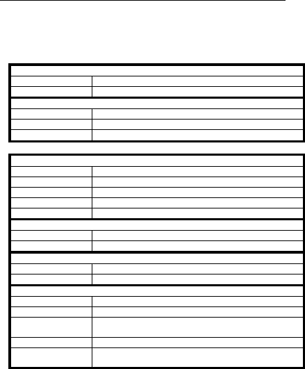
6.1. Smart Outlet™
Ethernet Interface
Standard IEEE-802.3
Connector RJ-45 – front panel
Range According to IEEE-802.3
Phone Line Interface
Connector Two RJ-11s – front panel
Pin-out
RJ-11 left (LINE 1)
Pins 3 and 4 – primary line
Pins 2 and 5 – secondary line
Pins 1 and 6 – non-filtered secondary line
RJ-11 right (LINE2)
Pins 3 and 4 – secondary line
Pins 2 and 5 – primary line
Pins 1 and 6 – non-filtered secondary line
Device Support Regular telephone sets, dial-up modems, faxes,
speakerphones, answering machines and caller ID systems
Smart OutletTM System Interface
Transmission Type Integrated voice, standard Ethernet, and power
Connector 3 pair terminal block – back panel
Terminal Block Wire
Support 22-28 AWG
Range between Smart
OutletsTM
Up to 150 feet (50 meters) over any type of cable.
Better wire (Cat. 3) quality enables range extension of up t
o
450 feet (150 meters)
Supported Wiring
Configurations Daisy chain or Star
Secondary Line Support
Transmission Type Regular telephony
Connector 1 pair terminal block – back panel
Terminal Block Wire
Support 22-28 AWG

52
Extended Phone Line Interface
Transmission Type Regular telephony
Connector 1 pair terminal block – back panel
Terminal Block Wire
Support 22-28 AWG
Regulatory UL, CUL, FCC B, CE
Mechanical
Dimensions (HxDxW) 4.57” x 3.07” x 0.79”
120 x 78 x 20 mm
Weight (approximate) 146 gr.
Operating
Temperature
32°F to 104°F
0° to 40°C
Operating Humidity 0-85% RH non-condensing
Storage Temperature -4°F to 158°F
-20°C to 70°C

53
6.2. Power Unit
Power
Maximum Input
Voltage 85-265 VAC
Power Consumption 65 Watts maximum
Output Voltage 55V – 59 VDC
Input Surge Protection 6 kV
Phone Line Interface
Ring Load 0.7 REN
DC Input Impedance Similar to one telephone set.
A
C Input/Output
Impedance
600 Ohm, 900 Ohm, or complex.
Depends on internal home telephone sets quantity
Connectors Rj-11 and terminal block – for direct connection, Mini-DIN
(via SRC-10FRST) – for indirect connection
Terminal Block Wire
Support 22-28 AWG
Phone Line Life Line
(Fail Safe) Supporting
Conditions
Power – OFF or SRC-POWERU failure
Smart Outlet System Interface
Connectors Mini-DIN and terminal block
Terminal Block Wire
Support 22-28 AWG
Short Circuit
Protection Protection against wires short circuit
Regulatory UL, CUL, FCC B, CE
Mechanical
Dimensions (HxDxW) 2” x 6” x 9”
50 x 152 x 230 mm
Weight (approximate) 870 gr.
Operating
Temperature
32°F to 104°F
0°C to 40°C
Operating Humidity 0-85% RH non-condensing
Storage Temperature -4°F to 158°F
-20°C to 70°C

54
6.3. Primary Smart OutletTM Adaptor
Phone Line Interface
Connector
Terminal block (for phone line access) – back panel
RJ-11 (for terminal equipment access) – bottom panel
Mini-DIN – bottom panel
Device Support Regular telephone sets, dial-up modems, faxes,
speakerphones, answering machines and caller ID systems
Phone Line Life Line
(Fail Safe) Supporting
Conditions
Power - OFF
Smart Outlet System Interface
Transmission Type Integrated phone (voice and signaling), standard Etherne
t
and power
Connector 1 pair of wires – back panel
Power Interface
Transmission Signals Power feeding
Connector Mini-DIN
Connection Method Mini-DIN cable (provided with the product)
Regulatory UL, CUL, FCC B, CE
Mechanical
Dimensions (HxDxW) 6.89” x 1.50” x 3.15”
175 x 38 x 80 mm
Weight (approximate) 250 gr.
Operating
Temperature
32°F to 104°F
0°C to 40°C
Operating Humidity 0-85% RH non-condensing
Storage Temperature -4°F to 158°F
-20°C to 70°C

55
6.4. StarBox
Power Interface
Transmission Signals Power and phone (voice and signaling)
Connector Terminal block
Terminal Block Wire
Support 22-28 AWG
Number of PU
Supported 2
Smart Outlet System Interface
Standard Smart Outlet (integrated voice, standard Ethernet and
power on single pair)
Connector 7 pair terminal block
Terminal Block Wire
Support 22-28 AWG
Number of Selectable
Branches between the
2 PUs
4
Ethernet Interface
Standard IEEE-802.3
Connector RJ-45
Range According to IEEE-802.3
Regulatory UL, CUL, FCC B, CE
Mechanical
Dimensions (HxDxW) 1.2” x 6” x 6.8”
30 x 152 x 172 mm
Weight (approximate) 380 gr.
Operating
Temperature
32°F to 104°F
0°C to 40°C
Operating Humidity 0-85% RH non-condensing
Storage Temperature -4°F to 158°F
-20°C to 70°C
56
6.5. Smartester
Power Interface
Battery +9VDC
Power Indication Green – OK, Red – low battery
Ethernet Interface
Standard IEEE-802.3
Connector 2 x RJ-45
RJ-45 pin out One direct PC connection and one cross-over connection
Telephone Interface
Telephony Indication LINE 1 and LINE 2
Indication Signal OFF-HOOK current
Minimum Current 6mA
Maximum Current 0.1A
Connector RJ-11
Front Panel Switches
ON/OFF Switch Enables operation or reset the product
RX/TX Selector Allows to choose operation mode
Front Panel Indicators
Telephone Indicators LINE 1 and LINE 2
LAN Indications TR (Transmit/Receive), ACT (Activity), and IND (Indication)
Mechanical
Dimensions (HxDxW) TBD
Weight (approximate) TBD
Operating
Temperature
32°F to 104°F
0°C to 40°C
Operating Humidity 0-85% RH non-condensing
Storage Temperature -4°F to 158°F
-20°C to 70°C

57
6.6. Surface Mount Adaptor
Mechanical
Dimensions (HxDxW) 0.4” x 3” x 4.6”
11 x 77 x 117 mm
Weight (approximate) 30 gr.
6.7. Wall Mount Adaptor
Mechanical
Dimensions (HxDxW) 0.9” x 2.9” x 4.5”
22 x 73 x 113 mm
Weight (approximate) 50 gr.

58
APPENDIXES
A. Topologies
Note: For the vast majority of homes, the following scenarios are
uncommon. Most homes have simple phone-wiring topologies.
However, in the rare instance of more complex wiring, the
following tables and diagrams will simplify the Smart Outlet™
installation process.
A.1. Typical Wiring Topologies
There are several possible typical wiring topologies when installing the
SercoNet network. In most cases, the demarcation point is inside the
home. However, in some rare cases, a Smart Outlet™ must be
placed outdoors (see next paragraph, ‘Demarcation Outside House’).
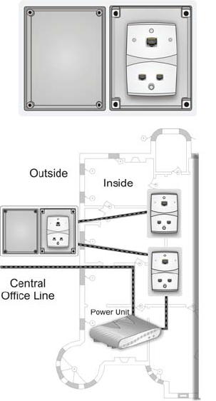
Demarcation Outside House
In this type of topology, the telephone connections must be made to
the outdoor Smart Outlet™ as the telephone wires are branched at
the demarcation point. In this case, a weatherproof box supplied by
SercoNet is necessary. See Figure A.1. and A.2. below.
There are two options for connecting the Power Unit with the Smart
Outlet™ located outside the house:
Option 1 Use an existing pair for connection between the C.O. and
the Power Unit and a second pair for connection between
the outdoor Smart Outlet™ and the indoor Power Unit or
Smart Outlet™ (See A.2 diagram).
Option 2 In cases where there is a physical way to run the mini-DIN
cable between the indoor and the outdoor locations, place
the Primary Smart Outlet™ Adaptor in the weather proof
box. Connect a mini-DIN cable between the Power Unit and
the Primary Smart Outlet™ Adaptor DIN connectors.
59
Figure A.1: Outdoor Smart Outlet™ installation
Figure A.2: Outside Demarcation
60
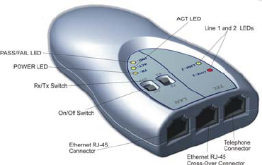
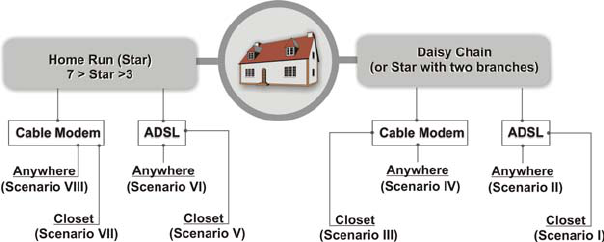
Topology Finder, Determination Flow Chart and Scenarios I – VIII
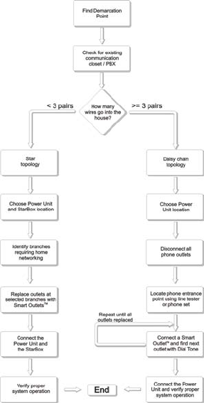
61
Determining House Topology
62
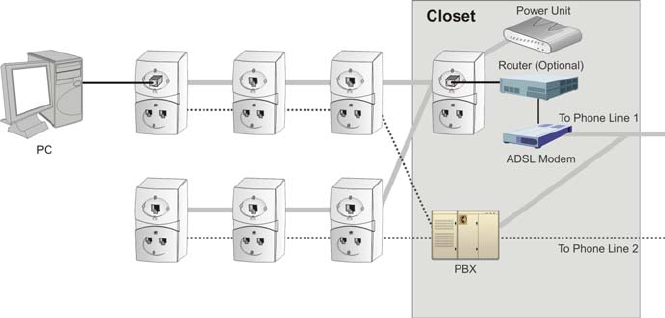
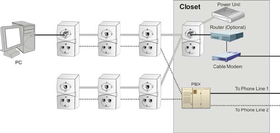
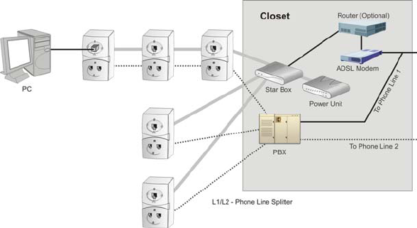
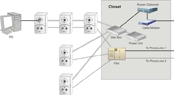
Topology Scenario I - a
Daisy Chain, ADSL, Closet, 4 Wires, PBX
63
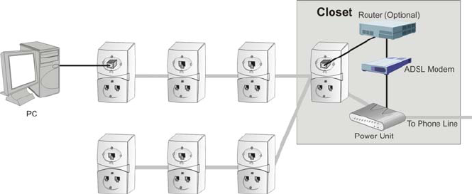
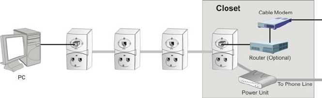
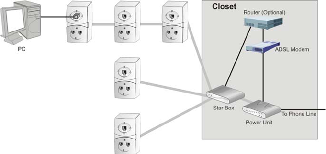
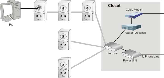
Topology Scenario I – b
Daisy Chain, ADSL, Closet, 2 Wires, No PBX
64
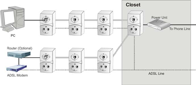
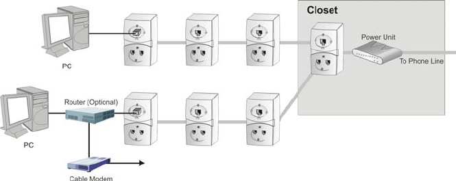
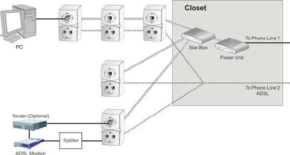
Topology Scenario II
Daisy Chain, ADSL, Anywhere, 4 Wires, No PBX
65
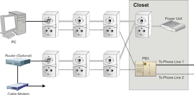
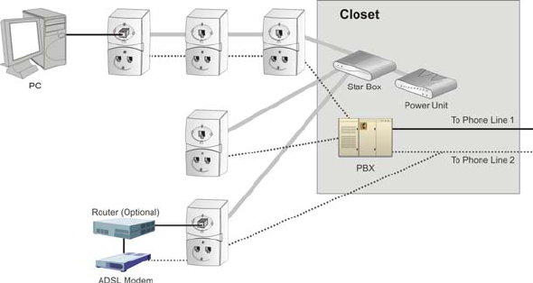
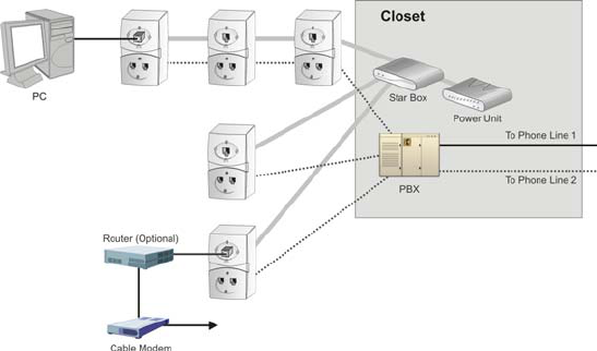
Topology Scenario III – a
Daisy Chain, ADSL, Closet, 4 Wires, PBX
66
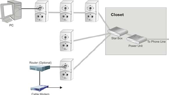
Topology Scenario III – b
Daisy Chain, Cable Modem, Closet, 2 Wires, No PBX
67
Topology Scenario IV – a
Daisy Chain, Cable Modem, Closet, 4 Wires, PBX
68
Topology Scenario IV – b
Daisy Chain, Cable Modem, Anywhere, 2 Wires, No PBX
69
Topology Scenario V – a
Home Run, ADSL, Closet, 4 Wires, PBX
70
Topology Scenario V – b
Home Run, ADSL, Closet, 2 Wires, No PBX
71
Topology Scenario VI – a
Home Run, ADSL, Anywhere, 4 Wires, No PBX
72
Topology Scenario VI – b
Home Run, ADSL, Closet, 4 Wires, PBX
73
Topology Scenario VII – a
Home Run, Cable Modem, Closet, 4 Wires, PBX
74
Topology Scenario VII – b
Home Run, Cable Modem, Closet, 2 Wires, No PBX
75
Topology Scenario VIII – a
Home Run, Cable Modem, Anywhere, 4 Wires, PBX
76
Topology Scenario VIII – b
Run Run, Cable Modem, Anywhere, 2 Wires, No PBX
77
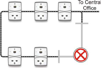
A.2. Topology Tips
• In some cases, the house wiring is laid out in a
closed loop. In these cases, one of the two
connections to the Central Office should be
disconnected, see the diagram below.
• During the Topology Finding stage, you may
reduce installation time by shorting the incoming
and outgoing pair at each outlet and follow the dial
tone throughout the house.
• Additional tips for reducing and simplifying the
installation procedure may be found at
http://www.serconet.net

78
B. Product List and Ordering
Information
Products
No. Catalog Number Description
1 SRC-10MPS SercoNet Smart Outlet™ –
10BT
2 SRC-POWERU Home power and central unit for
10BT
3 SRC-10AP802B Wireless Access Point IEEE-
802.11b outlet
4 SRC-10STAR StarBox for 10BT system
5 SRC-10FRST Primary Smart Outlet™ Adaptor
for 10BT system
6 SRC-MINITST Smartester for data and
telephone line existence testing
and diagnostics
Adaptors
No. Catalog Number Description
7 SRC-ADPSURF Surface mount adaptor
8 SRC-ADPADSLT ADSL Adaptor to connect phone
line1, phone line 2, ADSL
Modem line 2
9 SRC-ADPADSLC ADSL Adaptor cable to connect
phone line1, phone line2, ADSL
Modem line 2
10 SRC-ADPWMNT Wall mount adaptor
11 SRC-ADPOUTDOOR Outdoor box for Smart Outlet™

79
Cables
No. Catalog Number Description
12 SRC-CBLETH Cable set for 10BT RJ-45
straight
13 SRC-CBLETHX Cable set for 10BT RJ-45 Cross
14 SRC-CBLPUSA Power Cable for USA
15 SRC-CBLTRJ-11 Tel Cable RJ-11
16 SRC-CBLDIN Cable Mini DIN to connect Power
Unit to Outlet or StarBox
17 SRC-CBLSTRTB Cable from StarBox to phone
wiring box or PBX.
Documents
No. Catalog Number Description
18 SRC-DOC10MAN Operator manual for 10BT
system
19 SRC-DOCAPMAN Wireless Access Point Outlet
Manual
80
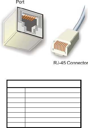
C. Phone and Data Cabling
Figure C.1. : RJ-45 Port and Connector
RJ-45 Color Chart
Wire 1 White with an Orange Stripe
Wire 2 Orange
Wire 3 White with a Green Stripe
Wire 4 Blue
Wire 5 White with a Blue Stripe
Wire 6 Green
Wire 7 White with a Brown Stripe
Wire 8 Brown
Table C.1: RJ-45 Color Chart
To recognize Wire 1, hold the cable so that the end of the plastic RJ-
45 tip (the part that goes into a wall jack first) is facing away from you.
Face the clip down so that the copper side faces up (the springy clip
will now be parallel to the floor). When looking down on the copper
side, Wire 1 will be on the far left.
81
D. Quick Networking Guide
D.1. Windows 98™
Step 1 – Verify that every PC has a unique IP address
There are two ways in which an IP address may be set – automatically
from a DHCP server or configuring manually a known unique IP
address.
3. Right-click the “Network Neighborhood” icon.
4. Select “Properties”.
5. Select the network card.
6. Click “Internet protocol (TCP/IP)”.
7. Select “Properties”.
8. Verify that the PC has a unique IP address.
Step 2 – Verify communications between PCs
Select “Start”, “Run” and type “Ping <IP address>” and press “Enter”.
The <IP address> should be the one set on the PC with which you
would communicate. This test should be repeated between every PC
that is connected to the SercoNet Smart Outlet™ network.
Step 3 – Become a client for Microsoft networks
1. Right-click the “Network Neighborhood” icon.
2. Select “Properties”.
3. Select the network card.
4. Click “Client for Microsoft Networks”.
5. Select “Add”.
6. Select “Client”.
7. Select “Microsoft”.
8. Select “Client for Microsoft Networks”.
9. Click “OK”.
Step 4 – Set the NetBEUI option for automatic detection of
network computers
82
1. Right-click the “Network Neighborhood” icon.
2. Select “Properties”.
3. Select the network card.
4. Click “Client for Microsoft Networks”.
5. Select “Add”.
6. Select “Protocol”.
7. Click “Add”.
8. Select “Microsoft”.
9. Select “NetBEUI”.
10. Click “OK”.
Step 5 – Assign a workgroup
1. Right-click the “Network Neighborhood” icon.
2. Select “Properties”.
3. Select “Identifications”.
4. Enter the workgroup to whom this computer should belong in
the “Workgroup” field.
Step 6 – Verify that other PCs are recognized as part of the
network
1. Click the “Network Neighborhood” icon.
2. Select “Entire Network”.
3. Select “Search for computers”. At this stage, all the
connected and properly configured computers should appear
on the screen.
Step 7 – Force the network to recognize other computers
If, after following the above steps, the network still does not recognize
all the PCs in your network segment, perform the following steps:
1. Activate the “Windows Explorer” search engine.
2. Search for “hosts.*” file.
3. Open the file using the “Notepad” editor.
4. In a new line, add the IP address and the missing PC’s
computer name.
5. Save the file
6. Reboot the PC.
83
Step 8 – Sharing files and computers
In order to use the network, it is recommended to share a common
space in each computer so that shared files can be stored. Computers
in the network can also use local printers connected to a specific PC.
1. Right-click the “Network Neighborhood” icon.
2. Select “Properties”.
3. Select “File and Printer Sharing”.
4. Check the two empty boxes and click “OK”.
5. Click the “My Computer” icon.
6. Browse until reaching the folder you would like to share. It is
possible to create a new folder for sharing purposes.
7. Right-click the folder to be shared.
8. Select “Properties”. There are multiple options available on
this screen for file sharing. Choose the most suitable for your
needs. Some options may require a password – verify that
the people involved are aware of the password for shared files
access.
D.2. Windows 2000™
Step 1 – Verify that every PC has a unique IP address
There are two ways in which an IP address may be set – automatically
from a DHCP server or configuring manually a known unique IP
address. Clicking with the right mouse, click on the “My Network
Places” icon can set these options. Select using right click on “Local
Area Connection” and select “Properties”, select the network card,
then click on the “Internet protocol (TCP/IP)” and select “Properties”.
Verify that the PC has a unique IP address.
Step 2 – Verify communications between PCs
Select “Start”, “Run” and type “Ping <<IP address>>” and press
“Enter”. The <<IP address>> should be the one set on the PC with
which you would communicate. This test should be repeated between
every PC that is connected to the SercoNet Smart Outlet™ network.
84
Step 3 – Set the NetBEUI option for automatic detection of
network computers
With the right mouse button click on the “My Network Places” icon,
select “Properties”, select “Local Area Connections” and select
“Properties”. Select the network card, select “Client for Microsoft
Networks” and then click on “Install”. Select “Protocol” and press the
“Add” button. Select “NetBEUI protocol” and press the “OK” button.
Step 4 – Assign a workgroup
With the right mouse button, click on the “My Computer” icon; select
“Properties”, select the “Network Identifications” and select
“Properties”. Fill the “Workgroup” field with the relevant workgroup to
whom this computer should belong. In case you work with a company
domain server, use the domain field option.
Step 5 – Verify that other PCs are recognized as part of the
network
With the left mouse button, click on “My network places” icon, select
“Entire Network” and select “Search for computers”. At this stage, all
the connected and properly configured computers should appear on
the screen.
Step 6 – Force the network to recognize other computers
If by following the above steps the network still does not recognize all
the PCs in your network segment, follow the next steps. Activate the
“Internet Explorer” search engine and search for the “hosts.*” file.
Open the file using the “Notepad” editor. In a new line, add the IP
address and computer name of the missing PC. Save the file and
reboot the PC.
Step 7 – Sharing files and computers
With the right mouse button, click on the “My Network Places” icon;
select “Properties”, select “Local Area Connections” and select
“properties”. Verify that the box next to “Files and Printers Sharing for
85
Microsoft Networks” is checked. Click on the “My Computer” icon and
browse until reaching the folder you would like to share. It is possible
to create a new folder for sharing purposes. Click with the right
mouse on the folder to be shared and select “Properties”. There are
multiple options available on this screen for file sharing. Choose the
option that best suits your needs. Some options may require a
password – verify that the people involved are aware of the password
for shared files access.
86
D.3. Windows XP™
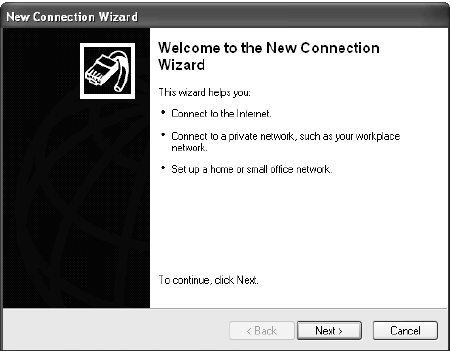
Step 1 Right-click " my network place " then "properties".
Step 2 Click "create a new connection".
a. Click “Next”.
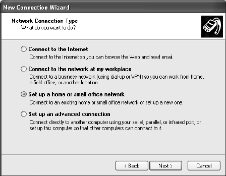
b. Choose the third option “Set up a home or small office
network” and click “Next”.
87
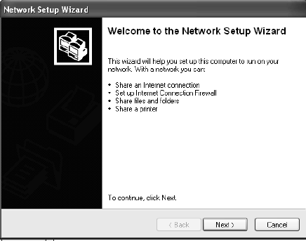
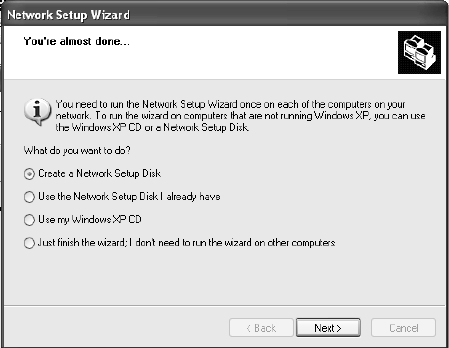
c. Click "finish" in the next window and a new network setup
wizard will pop up.
88
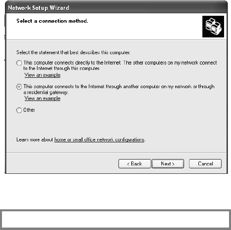
a. Click "Next" and click "Next" again.
b. If the PC connected directly to the Internet has an XP OS
installed on it then choose the first option.
c. If the PC uses another computer’s Internet connection or
gateway, then choose the second option.
d. Otherwise, choose ‘Other.’
89
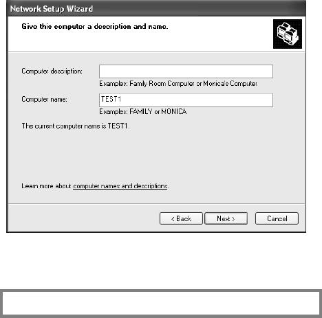
a. Click "Next".
b. Add the computer name.
Note: All computers on the network should have a unique
computer name.
c. Add the computer description (optional).
90
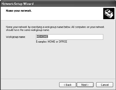
a. Click "Next".
b. Add the workgroup name.
Note: All computers on the network must have the same
workgroup name.
91
a. Click "Next".
b. Verify that the settings in the new window are and then
click ‘Next.’
c. Choose the best case for you.
92
a. Click ‘Next’ and then ‘Finish.’
b. You will be asked to restart your computer. Do so.
93
E. Glossary of Home-Networking Terms
10Base2 (thin Ethernet). The IEEE specifications for thin wire or
thin net Ethernet network cable with a maximum segment
length of 610.5 ft., using thin coaxial cable and daisy-chain
configuration for 10Mbps.
10baseT (The “T” stands for twisted pair cable) Sub specification of
IEEE-802.3 that requires the use of unshielded twisted pair
telephone cabling with RJ-45 phone jacks to be used by
Ethernet applications. The maximum length of a segment
of twisted pair cable is 330 feet. It is the most common
form of Ethernet, with a peak transmission speed of 10
Mbps using copper twisted-pair cable.
100baseT (The “T” stands for twisted pair cable) IEEE specification
for fast Ethernet, an upgraded standard for connecting
computers into a local area network (LAN). 100BaseT
Ethernet works just like regular Ethernet except that it can
transfer data at a peak rate of 100 Mbps. It's also more
expensive and less common than 10baseT.
Access point
An IEEE-802.11 term, referring to any device that
transports data between a wireless network and a wired
network or bridge between several wireless devices.
Asymmetric Digital Subscriber Line (ADSL)
A group of DSL technologies that allows for more data to
be transmitted over existing copper telephone lines.
Because they are asymmetric, more downstream
bandwidth is reserved (coming to the user from the
Internet) than upstream bandwidth (going from the user to
the Internet). This type of DSL is ideal for residential users
that do not need the same bandwidth speed in both
directions. The fastest downstream rate is 8 Mbps, and
the fastest upstream rate 640 Kbps.
94
Analog A continuously varying signal or wave. Telephone
transmission and/or switching that are not digital.
Attenuation
A decrease in a signal's strength (measured in decibels) as
it transmits over wires or cables. The shorter the wire or
cable the less attenuation occurs.
Backbone The part of a communications network that handles the
major traffic using the highest-speed and often longest
paths in the network. It is the centralized part of a large
network that links two or more sub networks and is the
primary path for data transmission
Bandwidth
A measurement of a communications channel/network
capacity. Greater bandwidth allows for more information
communication in a given period of time. Bandwidth is
measured in terms of analog signals (Hertz - Hz) or in
digital signals (Mbps).
Bit The basic unit in data communications, represented as
either a one or a zero.
Bit rate The number of bits of data transmitted over a line or media
per second
Bluetooth An open technology specification for short-range radio
links between wireless communication devices. Created by
an industry alliance known as the Bluetooth SIG (special
interest group).
Broadband
Represents the largest size bandwidth category, where
channels of data move over a single communication
medium, allowing information (data, voice, and video) to be
received and sent most quickly. Broadband uses xDSL,
cable and satellite systems.
Byte A compilation of bits.
95
Cable modem
A modem that provides a local area connection (connects
you computer to the Internet) by means of the cable
provided by your cable operator.
Category 3 or CAT3 Cable
Twisted pair copper cables rated for data rate networks
such as 10Mbps Ethernet.
Category 5 or CAT5 cable
A category of cabling that is used for local area networks
with voice and data needs. Category 5 describes network
cabling that consists of four twisted pairs of copper wire
terminated by RJ-45 connectors. CAT5 cabling supports
frequencies up to 100 MHz and speeds up to 1000 Mbps.
It can be used for ATM, token ring, 100Base-T, and
10Base-T networking. Computers working on LAN network
are connected using CAT5 cables.
Central Office Line
A telephone company facility that handles the switching of
telephone calls on the public switched telephone network
(PSTN) for a small regional area.
Coaxial cable
A conductor used in Ethernet networks protected with
shields of wire mesh and plastic insulation.
Crossover cable
A conductor for networking two computers without the use
of a hub.
Crosstalk Interference from an adjacent channel, i.e., when you are
able to hear a person on your telephone line that you did
not call, or when your mobile phone rings and interferes
with your Internet connection.
Customer Premises Equipment (CPE)
Any piece of equipment in a communication system that
resides on the customer's premises. Examples include
96
modems, television set-top boxes, telephones and
televisions.
Data link The communications link used for data transmission from a
source to a destination. For example, your telephone is a
data link.
Data transfer rate
The average number of bits per unit of time passing in a
data transaction.
Demarcation point
The boundary between the service provider domain and
the customer domain.
Dial-up connection
A data communication link established when the
communication equipment (e.g. a modem) dials a phone
number and negotiates a connection with the equipment
on the other end of the link.
Digital signal
A signal that takes on only two values, off or on, typically
represented by "0" or "1." Digital signals require less power
but (typically) require more bandwidth than analog.
Data over Cable Service Interface Specification (DOCSIS)
Developed by CableLabs, a standard for data
communication over cable television.
Dynamic Host Configuration Protocol (DHCP)
A TCP/IP protocol that allows servers to assign IP
addresses dynamically to PCs and workstations. The PC
or workstation "borrows" the IP address for a period of
time, then the IP address returns to the DHCP server for
reassignment.
97
E-1 A dedicated digital communication link provided by a
European telephone company that offers 2.048 Megabits
per second of bandwidth, commonly used for carrying
traffic to and from private business networks and Internet
service providers.
Ethernet An industry standard local area networking technology
(LAN) that supports data transfer rates of 10Mbps. It is the
most commonly used LAN standard. The most common
form of Ethernet is called 10BaseT, which denotes a peak
transmission speed of 10 mbps using copper twisted-pair
cable.
Fast Ethernet
Fast Ethernet is an upgraded standard for connecting
computers into a local area network (LAN). It works just
like regular Ethernet except that it can transfer data at a
peak rate of 100 mbps. Also referred to as 100BaseT, fast
Ethernet is more expensive and less common than its
slower 10BaseT sibling.
Firewall A security product that employs a combination of hardware
and software to prevent unauthorized users or traffic from
the Internet from gaining access onto a private local area
network (LAN).
Frequency
The rate at which an electromagnetic waveform (or
electrical current) alternates, usually measured in Hertz
(Hz).
Gateway A combination of software and hardware that links two
different types of networks.
High Bit-Rate Digital Subscriber Line (HDSL)
A symmetric DSL technology that provides a maximum
98
bandwidth of 1.5 Megabits per second in each direction
over two phone lines, or 2 Megabits per second over three
phone lines.
High Bit-Rate Digital Subscriber Line II (HDSL II)
A descendant of HDSL that offers the same performance
over a single phone line.
Home Networking
Connecting multiple electronic devices in a household by
way of a local area network (LAN).
Hub The point on a network where circuits are connected. It is a
device that links communication lines at a central location
in a network. It serves as a common wiring point so that
information can flow through one central location to any
other computer on the network.
Institute of Electrical and Electronics Engineers (IEEE)
An alliance comprised of engineers, scientists, and
students that sets standards for computers and
communications.
IEEE-802.X
The set of specifications for local area networks (LAN)
from the Institute of Electrical and Electronics Engineers
(IEEE).
IEEE-802.3
An IEEE specification for SCMA/CD based Ethernet
networks.
IEEE-802.11
A family of IEEE specifications for setting wireless LAN
standards. Specified for 1 and 2 Megabits per second
(Mbps) wireless Local Area Networks (LANs).
IEEE-802.11b
An IEEE specification for 5.5 or 11 Megabits per second
(Mbps) wireless Local Area Networks (LANs).
99
IEEE-1394 (also known as Firewire)
A universal standard serial interface that handles
multimedia bandwidth requirements for a variety of
devices.
Integrated Services Digital Network (ISDN)
A circuit-switched communication network, closely
associated with the public switched telephone network that
allows dial-up digital communication at speeds up to 128
Kilobits per second.
Internet Protocol (IP)
The standard signaling method used for all communication
over the Internet.
Internet Service Provider (ISP)
An organization offering and providing Internet access to
the public using computer servers connected directly to the
Internet.
Intranet A network serving a single organization or site that is
modeled after the Internet, allowing users access to almost
any information available on the network. Unlike the
Internet, intranets are typically limited to one organization
or one site, with little or no access to outside users.
IP Address
A numeric identifier for your computer.
Local Area Network (LAN)
A network connecting a number of computers to each
other or to a central server so that the computers can
share programs and files.
Local loop
The copper lines between a customer's premises and a
telephone company's central office, also known as “Last
Mile” connections.
100
Mbps Megabits per second. One million bits per second.
Megabit One million bits.
Megabyte 1,000,000 bytes, or 1,000 kilobytes.
Megahertz (MHz)
One million cycles per second.
Microcell
A bounded physical space in which a number of wireless
devices can communicate.
Modem (modulator-demodulator)
A device that converts digital data and analog signals for
transmission over a telephone or cable line.
Multicast The transmission of information over the Internet to a
select group of recipients on a network.
Multimedia Content
Information containing multiple data types (audio, voice,
files)
Narrowband
A designation of bandwidth less than 56 Kilobits per
second.
Network Access Provider (NAP)
Another name for a provider of networked telephone and
associated services, usually in the U.S.
Network Interface Card (NIC)
A card that connects a workstation to a local area network.
Network Service Provider (NSP)
A high-level Internet provider that offers high-speed
backbone services.
Network Termination Equipment (NTE)
The equipment at the ends of the communication path.
101
Node Any network station.
Private Branch exchange (PBX)
A private phone switching system that connects
telephones to each other, allowing users to make inbound
as well as outbound telephone calls. In most companies, a
digital PBX switching system utilizes digital telephones and
includes features such as voicemail, call management, and
caller ID.
Peripheral
An electronic device, such as a printer or scanner, that is
not integral to running a PC, but increases the PC’s
capabilities.
Plain Old Telephone Service (POTS)
An acronym identifying the traditional function of a
telephone network to allow voice communication between
two people across a distance.
Point of Presence (POP)
The physical point of connection between a data network
and a telephone network.
POTS splitter
A device that uses filters to separate voice from data
signals when they are to be carried on the same phone
line, required for several types of DSL services.
Point-to-Point Protocol (PPP)
A protocol allowing a computer to access the Internet using
a dial-up phone line and a high-speed modem. This can be
accomplished over Ethernet (PPPoE), or over
Asynchronous Transfer Mode (ATM; PPPoA)
Protocol A standard for data transmission between two devices.
Public Switched Telephone Network (PSTN)
The worldwide communications network that carries phone
calls and data.
102
QoS (Quality of Service)
The performance properties of a network service, including
throughput and priority.
Residential Gateway
A device that bridges the Broadband Internet connection
and the home network.
RJ-11 Connector
Short for Registered Jack-11, the RJ-11 is a six-wire jack
used to connect telephone equipment.
RJ-45 Connector
A connector used for the 10baseT, 100baseT and
100baseT4 type of networks. It is a small flat plastic
connector with 8 pins. 10BbaseT/100baseT uses pairs 2
and 3 only. 100baseT4 uses pairs 1,2,3,4
Router The central switching device in a packet-switched
computer network that directs and controls the flow of data
through the network.
Scalable network
A network that can easily expand in size.
Security Ensuring that data stored in a computer cannot be read by
outside parties.
Standard A definition that has been approved by recognized
standards organizations in the relevant industry.
Standards are important in the computer industry because
they allow the combination of products from different
manufacturers to create a customized system.
Switch A device that selects paths or circuits. Routers are smart
switches.
103
Twisted pair
The set of two copper wires used to connect a telephone
customer with a switching office, loosely wrapped around
each other to minimize interference from other twisted
pairs in the same bundle.
Universal Serial Bus (USB)
A computer interface with a maximum bandwidth of 1.5
Megabytes per second used for connecting computer
peripherals such as printers, keyboards and scanners.
Value-added services
Applications such as VoIP, video streaming, and
interactive gaming that are enabled through broadband
service.
Very High Bit-rate Digital Subscriber Line (VDSL)
A type of asymmetric DSL that delivers from 13 to 52
Megabits per second downstream bandwidth and 1.5 to
2.3 Megabits per second upstream.
Video on Demand (VOD)
A pay-per-view television service in which a viewer can
order a program from a menu and have it delivered
instantly to the television set, typically with the ability to
pause, rewind, etc.
Voice over IP (VoIP)
Technology that enables people to use the Internet as the
transmission medium for phone calls.
Wide Area Network (WAN)
A network that interconnects geographically distributed
computers or local area networks.
104
F. FAQ
How does SercoNet’s Smart Outlet™ network function as
the Ethernet home backbone?
The SercoNet system works through the existing phone wires in the
home. The Smart Outlets™ supply the user with an Ethernet
backbone in addition to the phone services. All services transferable
over standard Ethernet are available with the SercoNet Smart Outlet™
network in the home environment.
How fast does the SercoNet system work?
The SercoNet Smart Outlet™ network guarantees 10Mbps over all
existing phone wires. With IEEE-802.11b outlets there may be data
rate degradation due to limitations of wireless technology.
Is any computer configuration necessary?
No. As long as a network has been previously set up before installing
the SercoNet Smart Outlet™ network, then the SercoNet system
functions as a “HUB” between the computers. If you did not have a
network previously set up on your computer, then you must configure
a network using Windows standard tools for networking. Once you
have configured the networking environment, you may connect the
computers using the SercoNet Smart Outlets™.
Will any new wires have to be installed?
No. The SercoNet Smart Outlet™ network runs on existing phone
wires over any wire topology.
105
Will the phone be affected after installing the SercoNet
system?
The phone will continue to operate as it had prior to the SercoNet
system installation.
Can dial-up Internet or fax operate simultaneously with the
SercoNet system?
Yes. The SercoNet system has no effect on dial-up connections or fax
transmissions. The systems can operate simultaneously.
How are network devices (computer, printer, cable modem,
etc.) connected to the SercoNet Smart Outlets™?
Each device is connected to one of the Smart Outlets™ by an
Ethernet cable. Some Broadband modems may require an Ethernet
CAT5 cross cable to connect to the SercoNet Smart Outlet™ network.
The protocol that runs between the Smart Outlets™ is standard
Ethernet 10BT.
What specific Windows versions are supported?
The SercoNet system supports all Windows versions, as long as they
in turn support Ethernet and networking.
In case of a power outage, will the telephone still work?
The SercoNet system is designed to support lifeline telephony. In the
case of a power outage, the telephone lines will continue to operate in
the manner prior to your SercoNet system installation.
106
If a neighbor has a phone-line home network, will the Smart
Outlet™ network cause interference?
The SercoNet system does not transmit outside the house. It filters all
incoming and outgoing signals, and does not cause interference on
neighbors’ lines.
Does the Smart Outlet™ system support two phone-line
connections ?
Yes. Each Smart Outlet™ includes a special terminal block connector
enabling the connection of a second telephone and dual RJ-11 front
panel connectors for direct connection of two telephone sets.
What is the benefit of combining wired and wireless?
The wired network is a reliable and robust solution. However, in many
cases, mobility and accessibility are the key customer request. The
mobility of wireless is enhanced by the performance of the SercoNet
backbone connected to the broadband service. An added benefit of
combined SercoNet wireless solution is the flexibility of the wireless
access point placement for optimum signal strength.

107
G. Customer Support
For help with the installation or operation of your SercoNet Smart
Outlet™ and Power Unit, contact Customer Support at the following
telephone and fax numbers, e-mail addresses and web sites:
North America
Tel: 1-800-396-9887
Office: (508) 229-3670
Fax: (508) 229-3601
International
Tel: +972-9-7411833
Fax: +972-9-7481333
E-mail: support@serconet.net
Please visit our Website at www.serconet.net
108
H. Warranty Information
SercoNet guarantees that the SercoNet Smart Outlet™ network, including its
Power Unit, is free from any physical defects in material or workmanship
under normal use for a period of one year from the date of purchase. If the
products prove to be defective during the warranty period, contact SercoNet
Customer Support.
Note: SercoNet's warranty does not extend to any equipment that has
been damaged through negligence. The warranty only covers
equipment supplied by SercoNet.
LIMITED WARRANTY
SercoNet Ltd. (“SercoNet”) provides this limited warranty for its product only to
the person or entity that originally purchased the product from SercoNet or its
authorized reseller or distributor.
Limited Hardware Warranty: SercoNet warrants that the hardware portion of
the SercoNet products described below (“Hardware”) will be free from material
defects in workmanship and materials from the date of original retail purchase
of the hardware, for the period set forth below applicable to the product type
(“Warranty Period”) if the Hardware is used and serviced in accordance with
applicable documentation and proof-of-purchase.
Product Type Warranty Period
Product (excluding power supplies), if purchased
and delivered in the fifty (50) United States, or
the District of Columbia (“USA”)
Standard One (1) Year
Product purchased or delivered outside the USA One (1) Year
Power Supplies One (1) Year
Spare parts and spare kits Ninety (90) days
SercoNet’s sole obligation shall be to repair or replace the defective Hardware
at no charge to the original owner. Such repair or replacement will be
rendered by SercoNet at an Authorized SercoNet Service Office. The
replacement Hardware need not be new or of an identical make, model or
part; SercoNet may in its discretion replace the defective Hardware (or any
part thereof) with any reconditioned product that SercoNet reasonably
determines is substantially equivalent (or superior) in all material respects to
the defective Hardware. The Warranty Period shall extend for an additional
ninety (90) days after any repaired or replaced Hardware is delivered. If a

109
material defect is incapable of correction, or if SercoNet determines in its sole
discretion that it is not practical to repair or replace the defective Hardware,
the price paid by the original purchase for the defective Hardware will be
refunded by SercoNet upon return to SercoNet of the defective Hardware. All
Hardware (or part thereof) that is replaced by SercoNet, or for which the
purchase price is refunded, shall become the property of SercoNet upon
replacement or refund.
Limited Software Warranty: SercoNet warrants that the software portion of
the product (“Software”) will substantially conform to SercoNet’s then current
functional specifications for the Software, as set forth in the applicable
documentation, from the date of original delivery of the Software for a period
of one (1) year (“Warranty Period”), if the Software is properly installed on
approved hardware and operated as contemplated in its documentation.
SercoNet further warrants that, during the Warranty Period, the magnetic
media on which SercoNet delivers the Software will be free of physical
defects. SercoNet’s sole obligation shall be to replace the non-conforming
Software (or defective media) with software that substantially conforms to
SercoNet’s functional specifications for the Software. Except as otherwise
agreed by SercoNet in writing, the replacement Software is provided only to
the original licensee, and is subject to the terms and conditions of the license
granted by SercoNet for the Software. The Warranty Period shall extend for
an additional one (1) year after any replacement Software is delivered. If a
material non-conformance is incapable of correction, or if SercoNet
determines in its sole discretion that it is not practical to replace the non-
conforming Software, the price paid by the original licensee for the non-
conforming Software will be refunded by SercoNet; provided that the non-
conforming Software (and all copies thereof) is first returned to SercoNet. The
license granted respecting any Software for which a refund is given
automatically terminates.
What You Must Do For Warranty Service:
Proof of Purchase. Proof of purchase shown to the Authorized SercoNet
Service Office is required for each SercoNet product within one year after the
product is purchased and/or licensed in order to validate the warranty. The
addresses/telephone/fax list of the nearest Authorized SercoNet Service
Office is provided in the back of this manual. FAILURE TO SHOW PROPER
PROOF-OF-PURCHASE MAY AFFECT THE WARRANTY FOR THIS
PRODUCT.
Submitting a claim. Any claim under this limited warranty must be submitted
in writing before the end of the Warranty Period to an Authorized SercoNet
Service Office. The claim must include a written description of the Hardware

110
defect or Software non-conformance in sufficient detail to allow SercoNet to
confirm the same. The original product owner must obtain a Return Material
Authorization (RMA) number from the Authorized SercoNet Service Office
and, if requested, provide written proof of purchase of the product (such as a
copy of the dated purchase invoice for the product) before the warranty
service is provided. After an RMA number is issued, the defective product
must be packaged securely in the original or other suitable shipping package
to ensure that it will not be damaged in transit, and the RMA number must be
prominently marked on the outside of the package. The packaged product
shall be insured and shipped to SercoNet Inc., with all shipping costs prepaid.
SercoNet may reject or return any product that is not packaged and shipped in
strict compliance with the foregoing requirements, or for which an RMA
number is not visible from the outside of the package. The product owner
agrees to pay SercoNet any reasonable handling and return shipping charges
for any product that is not packaged and shipped in accordance with the
foregoing requirements, or that is determined by SercoNet not to be defective
or non-conforming.
What Is Not Covered: The limited warranty provided by SercoNet does not
cover:
A. Products that have been subjected to abuse,
accident, alteration, modification, tampering,
negligence, misuse, faulty installation, lack of
reasonable care, repair or service in any way that is
not contemplated in the documentation for the
product, or if the model or serial number has been
altered, tampered with, defaced or removed;
B. Initial installation, installation and removal of the
product for repair, and shipping costs;
C. Operational adjustments covered in the operating
manual for the product, and normal maintenance;
D. Damage that occurs in shipment, due to an act of
God, failures due to power surge, and/or cosmetic
damage; and
E. Any hardware, software, firmware or other products
or services provided by anyone other than SercoNet.
Disclaimer of Other Warranties: EXCEPT FOR THE LIMITED WARRANTY
SPECIFIED HEREIN, THE PRODUCT IS PROVIDED “AS-IS” WITHOUT
ANY WARRANTY OF ANY KIND INCLUDING, WITHOUT LIMITATION, ANY
WARRANTY OF MERCHANTABILITY, FITNESS FOR A PARTICULAR
PURPOSE AND NON-INFRINGEMENT. IF AN IMPLIED WARRANTY
111
CANNOT BE DISCLAIMED IN ANY TERRITORY WHERE A PRODUCT IS
SOLD, THE DURATION OF SUCH IMPLIED WARRANTY SHALL BE
LIMITED TO ONE (1) YEAR. EXCEPT AS EXPRESSLY COVERED UNDER
THE LIMITED WARRANTY PROVIDED HEREIN, THE ENTIRE RISK AS TO
THE QUALITY, SELECTION AND PERFORMANCE OF THE PRODUCT IS
WITH THE PURCHASER OF THE PRODUCT.
Limitation of Liability: TO THE MAXIMUM EXTENT PERMITTED BY LAW,
SERCONET IS NOT LIABLE UNDER ANY CONTRACT, NEGLIGENCE,
STRICT LIABILITY OR OTHER LEGAL OR EQUITABLE THEORY FOR ANY
LOSS OF USE OF THE PRODUCT, INCONVENIENCE OR DAMAGES OF
ANY CHARACTER, WHETHER DIRECT, SPECIAL, INCIDENTAL OR
CONSEQUENTIAL (INCLUDING, BUT NOT LIMITED TO, DAMAGES FOR
LOSS OF GOODWILL, WORK STOPPAGE, COMPUTER FAILURE OR
MALFUNCTION, LOSS OF INFORMATION OR DATA CONTAINED IN,
STORED ON, OR INTEGRATED WITH ANY PRODUCT RETURNED TO
SERCONET FOR WARRANTY SERVICE) RESULTING FROM THE USE OF
THE PRODUCT, RELATING TO WARRANTY SERVICE, OR ARISING OUT
OF ANY BREACH OF THIS LIMITED WARRANTY, EVEN IF SERCONET
HAS BEEN ADVISED OF THE POSSIBILITY OF SUCH DAMAGES. THE
SOLE REMEDY FOR A BREACH OF THE FOREGOING LIMITED
WARRANTY IS REPAIR, REPLACEMENT OR REFUND OF THE
DEFECTIVE OR NON-CONFORMING PRODUCT.
Governing Law: This Limited Warranty shall be governed by the laws of the
State of New York. Some states do not allow exclusion or limitation of
incidental or consequential damages, or limitations on how long an implied
warranty lasts, so the foregoing limitations and exclusions may not apply.
This limited warranty provides specific legal rights and the product owner may
also have other rights which vary from state to state.

112
I. Approvals
I.1. FCC / PART 15 Compliance Statements
I.1.1 FCC / PART 15 Notification
The FCC Wants You to Know
This equipment has been tested and found to comply with the limits
for a Class B digital device, pursuant to Part 15 of the FCC rules.
These limits are designed to provide reasonable protection against
harmful interference in a residential installation. This equipment
generates, uses and can radiate radio frequency energy and, if not
installed and used in accordance with the instructions, may cause
harmful interference to radio communications. However, there is
no guarantee that interference will not occur in a particular
installation. If this equipment does cause harmful interference to
radio or television reception, which can be determined by turning
the equipment off and on, the user is encouraged to try to correct
the interference by one or more of the following measures:
a) Reorient or relocate the receiving antenna.
b) Increase the separation between the equipment and receiver.
c) Connect the equipment to an outlet on a circuit different from
that to which the receiver is connected.
d) Consult the dealer or an experienced radio/TV technician.
FCC Warning
Modifications not expressly approved by the
manufacturer could void the user authority to
operate the equipment under FCC Rules.
Tested To Comply With FCC Standards
FOR HOME OR OFFICE USE

113
I.1.2 FCC / PART 15 Compliance Conditions:
This device complies with Part 15 of the FCC Rules.
Operation is subject to the following two conditions:
(1) This device may not cause harmful interference, and
(2) This device must accept any interference received,
including interference that may cause undesired operation.
I.1.3 FCC / PART 15 Declaration Of Conformity
regarding the Wireless Access Point (WAP) Unit,
Model SRC-10AP802B
FCC Declaration Of Conformity
We, the undersigned,
Company: SercoNet Inc.
Address: Deerfoor Office Park, 257 Turnpike Road, Suite 340,
Southborough,
MA 01772
Country: U.S.A.
Telephone Number: 508-229-3670
Fax Number: 508-229-3671
are the Responsible Party for this Declaration, certify and
declare under our sole responsibility that the following equipment:
Brand Type Product
Description
Smart Outlet System,
Wireless Access
SRC-10AP802B 2.4 GHz Wireless
Access Point
113
I.1.2 FCC / PART 15 Compliance Conditions:
This device complies with Part 15 of the FCC Rules.
Operation is subject to the following two conditions:
(1) This device may not cause harmful interference, and
(2) This device must accept any interference received,
including interference that may cause undesired operation.
I.1.3 FCC / PART 15 Declaration Of Conformity
regarding the Wireless Access Point (WAP) Unit,
Model SRC-10AP802B
Brand Type Product
Description
Smart Outlet System,
Wireless Access
SRC-10AP802B 2.4 GHz Wireless
Access Point
Point
IEEE-802.11b
complies with Part 15 of the FCC Rules.
Operation is subject to the following two conditions:
(1) this device may not cause harmful interference, and
(2) this device must accept any interference received, including
interference that may cause undesired operation.
Date:
Company Stamp:
Signature:
Name and Function:
I.1.4 FCC / PART 15 Warning regarding the Wireless
Access Point (WAP) Unit, Model SRC-10AP802B:
The antenna used for this transmitter must be installed to
provide a separation distance of at least 20 cm from all
persons and not be co-located or operating in conjunction
with any other antenna or transmitter.

115
I.2. FCC / PART 68 Compliance Statements
I.2.1 Customer Information Statement
General Requirements for ALL Equipment:
1. This equipment complies with 47 CFR, Part 68 of the rules.
On the rear side of the SRC-POWERU, SRC-10MPS and SRC-
10FRST Units of this equipment is a label that contains, among
other information, the certification number and ringer equivalence
number (REN) for this equipment. If requested, this information
must be provided to the telephone company.
2. The Application Certification Jack USOC (Universal Service
Order Code) used for the equipment is RJ11C.
3. A compliant telephone cord and modular plug is provided with
this equipment. This equipment is designated to be
connected to the telephone network or premises wiring using
a compatible modular jack which is Part 68 compliant. See
installation instructions for details.
4. If the terminal equipment Smart Outlet System causes harm
to the telephone network, the telephone company will notify
you in advance that temporary discontinuance of service may
be required. But if advance notice is not practical, the
telephone company will notify the customer as soon as
possible. Also, you will be advised of your right to file a
complaint with the FCC if you believe it is necessary.
5. The telephone company may make changes in it’s facilities,
equipment, operations, or procedures that could affect the
operation of the equipment. If this happens the telephone
company will provide advance notice in order for you to make
the necessary modifications to maintain uninterrupted
services.
116
6. If trouble is experienced with this equipment Smart Outlet
System, for repairs or warranty information, please contact
SercoNet Inc., Deerfoot Office Park, 257 Turnpike Road,
Suite 340, Southborough, MA 01772,
Tel. 508-229-3670, Fax. 508-229-3671. If the equipment is
causing harm to the telephone network, the telephone company
may request that you disconnect the equipment until the problem
is resolved.
7. No repairs can be performed on the Smart Outlet System by
the customer (user).
8. The equipment cannot be used on public coin phone services
provided by the telephone company. Connection to party line
services is subject to state tariffs. Contact the state public
utility commission, public service commission, or corporate
commission for information.
117
I.2.2 FCC / PART 68 Product Label Sample and
Statement
The following is a Short Form representative drawing of the FCC /
ACTA Label for the Model SRC-POWERU that appears at the rear
side of the Model SRC-POWERU:
The Complete Form of the above label appears below, as follows:
The structure of the Serial Number appearing at the above label is as
follows:
• V indicates the Vendor / Manufacturer Name.
• YY indicate two digits, ranging from 00 to 99, for the Year.
• WW indicate two digits, ranging from 00 to 54, for the Week.
• SSSSS indicate five digits, ranging from 00000 to 99999, for
the Serial Number.
Certification Number: US: AAAHN05BSI010
Model Number: SRC-POWERU
Complies with 47 CFR Part 68
Certification Number: US: AAAHN05BSI010
Ringer Equivalence Number: 0.5B
Made in Israel
Use USOC Jack: RJ11C
Responsible Party Name: SerCoNet Ltd.
Model Number: SRC-POWERU
Serial Number: VYYWWSSSSS
118
I.2.3 FCC / PART 68 FIC/SOC Codes for Analog
Equipment Facility Interface Codes and Service
Order Code
FIC Codes for Analog Equipment:
Applies (x)
FIC Codes Description
√ 02LS2 2-Wire, Local Switched Access, Loop-Start
- 02GS2 2-Wire, Local Switched Access, Ground-Start
- 02RV2-0 2-Wire, DID, Customer Originates (only for
E911 Identification Service)
- 02RV2-T 2-Wire, Local Switched Access, Reverse
Battery, Customer Term, DID Ports
- *04LS2 4-Wire, Local Switched Access, Loop-Start
- *04GS2 4-Wire, Local Switched Access, Ground-Start
- *04RV2-T 4-Wire, Local Switched Access, Reverse
Battery, Customer Termination
- 02LR2 2-Wire, Private Line Automatic Ring-down
- 04LR2 4-Wire, Private Line Automatic Ring-down
* Subject to local availability
SOC Code for Analog Equipment:
Applies (x)
SOC Codes
Description
√
9.0F Provides full protection to the Network from
systems using live voices.
Only registered terminal equipment can be
connected to station ports.
-
9.0N Unprotected systems. Requires use of
registered protective couplers or filing of
affidavits with the telco. See Section 68.215
(d) and (e).
-
9.0Y Provides full Part 68 protection. Provides
signal limiting for all signal sources
(not just MOH)
- 7.0Y Provides total protection to the network for
connection for private communication systems.
119
Copyright © SercoNet, all rights are reserved. Smart Outlet™ is a registered
trademark of SercoNet. Microsoft Windows 98 (WIN98), Windows ME,
Windows XP (WINXP), Windows 2000 (WIN2000), and Windows NT are
trademarks of the Microsoft Corporation. All other trademarks are registered
trademarks or trademarks of their respective holders.
All specifications and information are subject to change without notice.

120
International Headquarters
SercoNet Ltd.
16 Ha'haroshet St
Ra'anana 43657
Israel
North America Headquarters
SercoNet Inc.
257 Turnpike Road, Suite 340
Southborough, MA 01772
Toll-free: 1-800-396-9887
Tel: +972-9-7411833 Tel: 508.229.3670
Fax: +972-9-7481333 Fax: (508) 229-3671
E-mail:
marketing@serconet.net
Web Site: www.serconet.net