Sercomm 0K30 Wireless Access Point User Manual 706ST
Sercomm Corporation Wireless Access Point 706ST
UserManual.wiki
>
Sercomm
>
0K30 User Manual
users manual
Navigation menu
Upload a User Manual
Namespaces
Wiki Guide
HTML
PDF
Info
Views
User Manual
Discussion / Help
Navigation
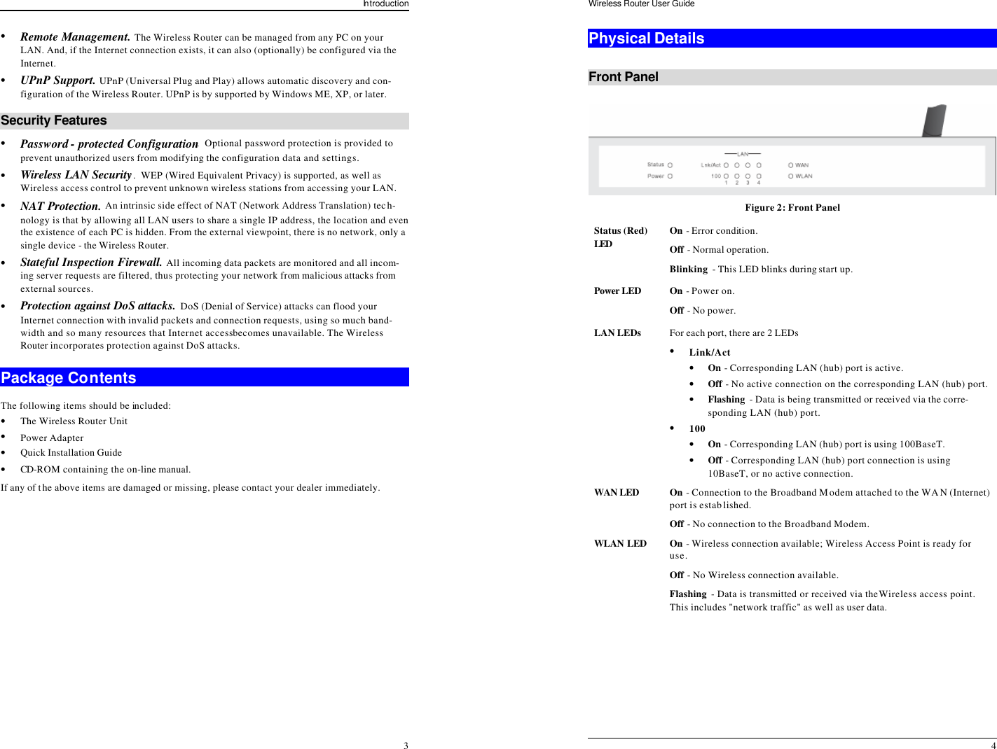
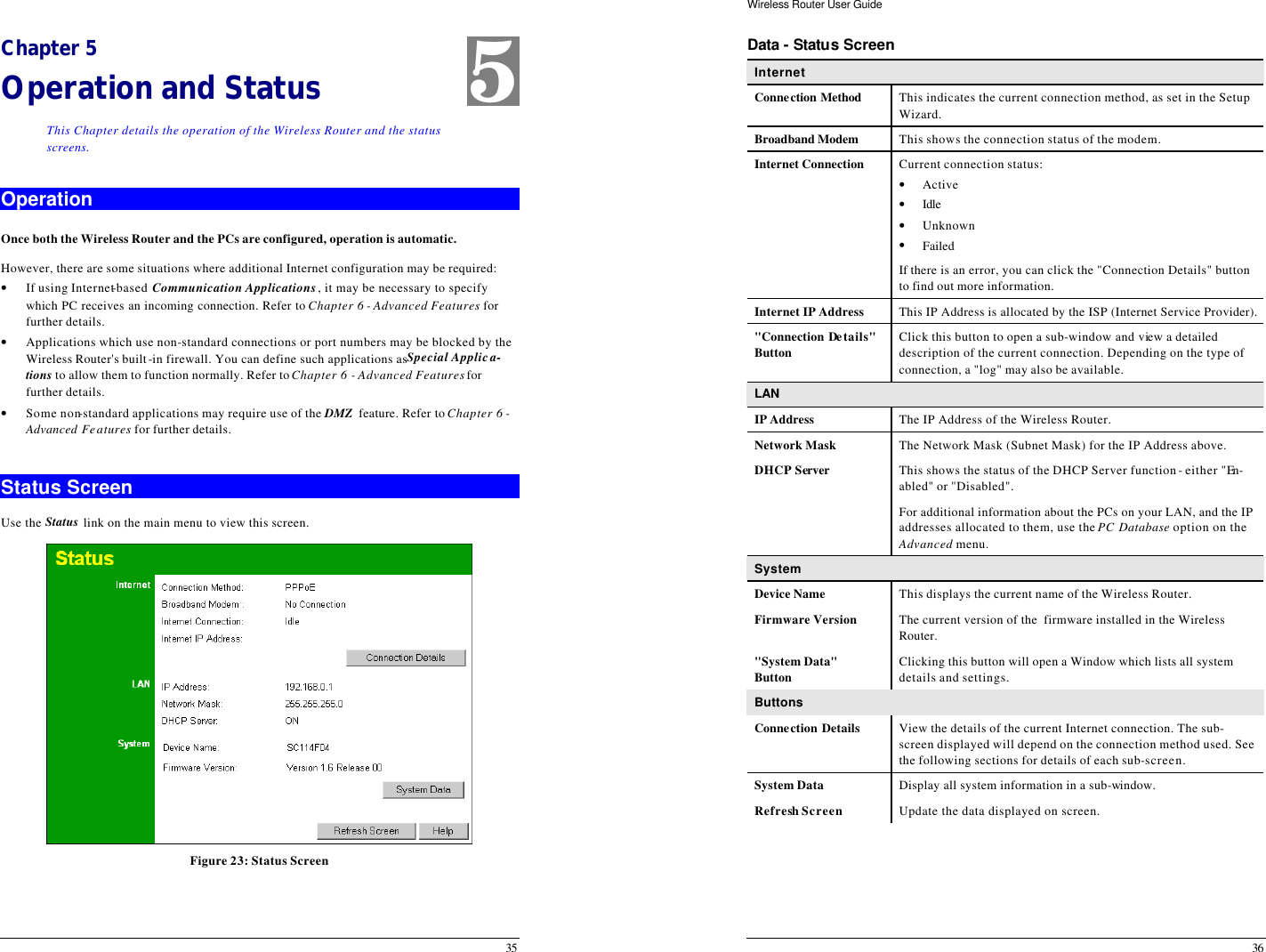
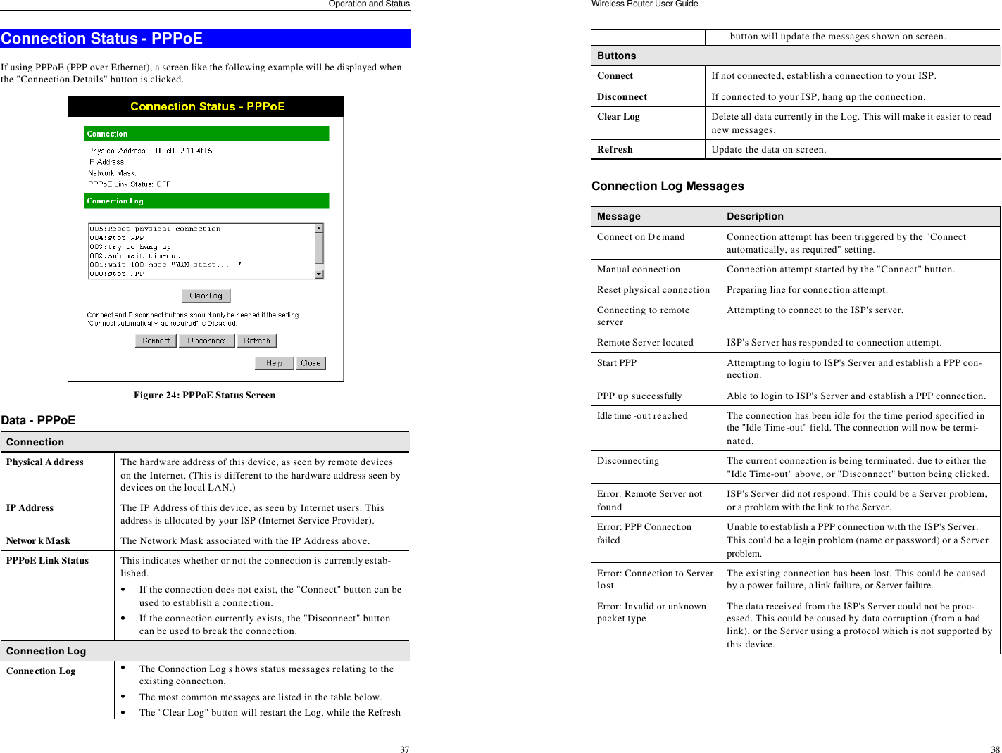
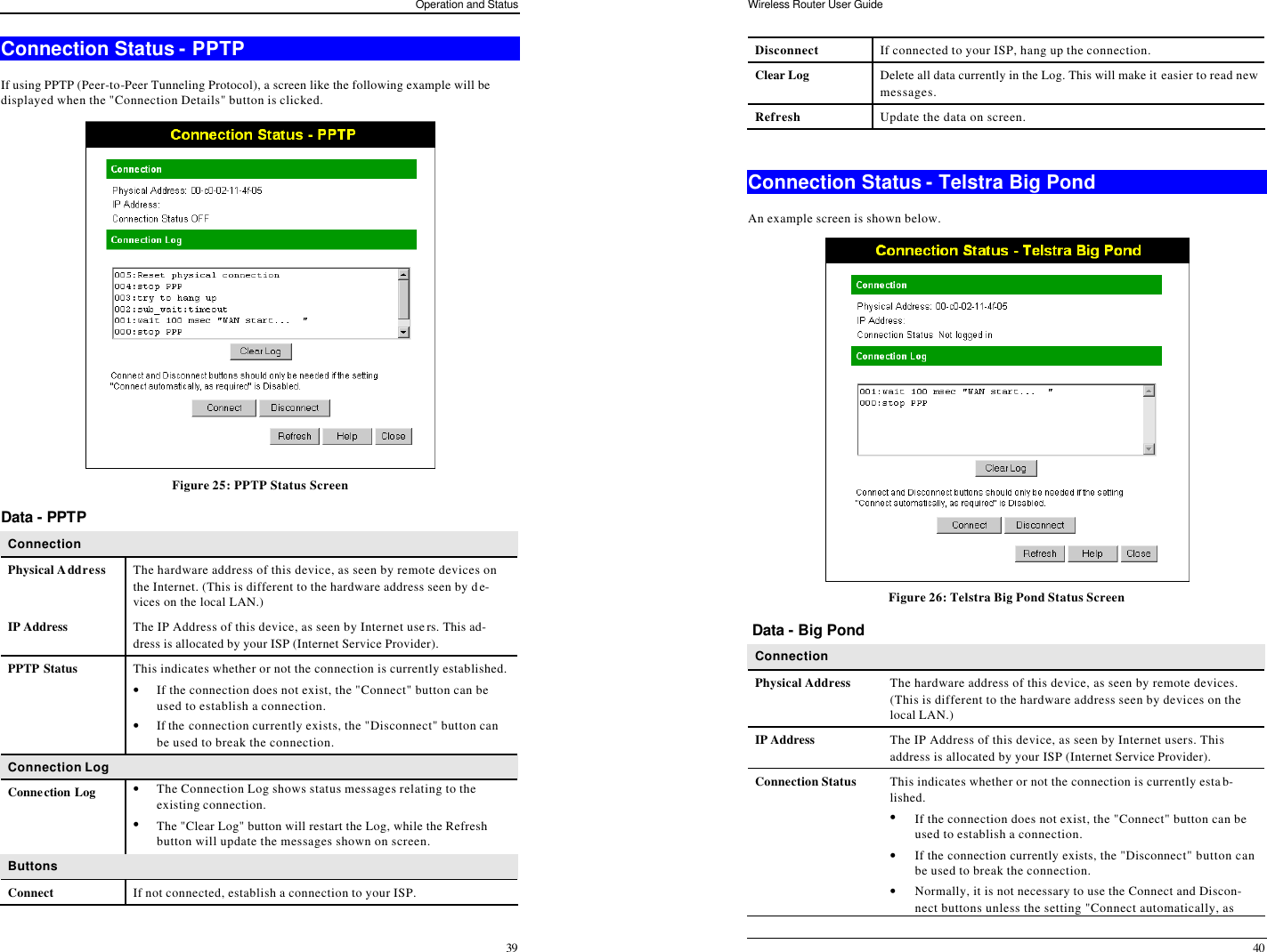
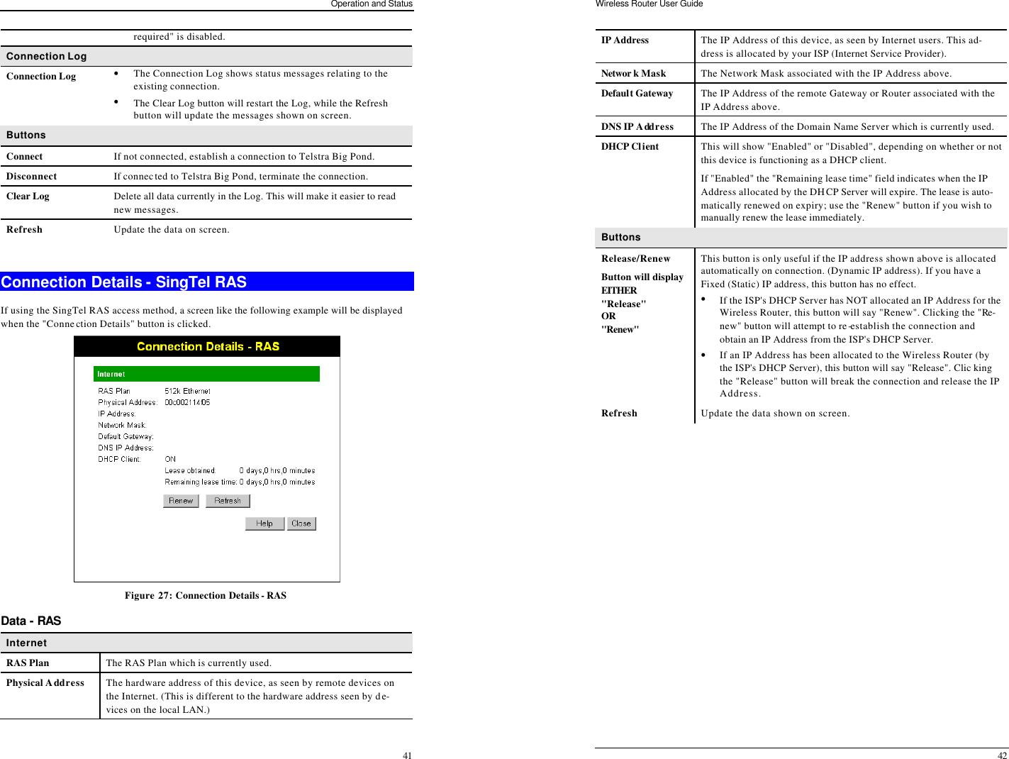
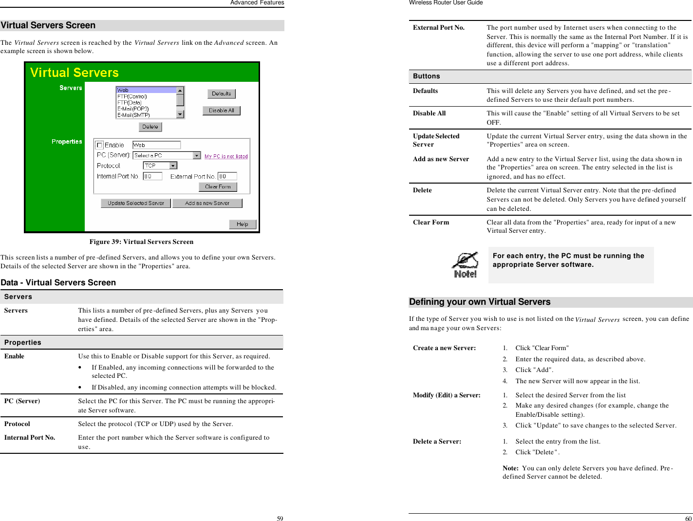
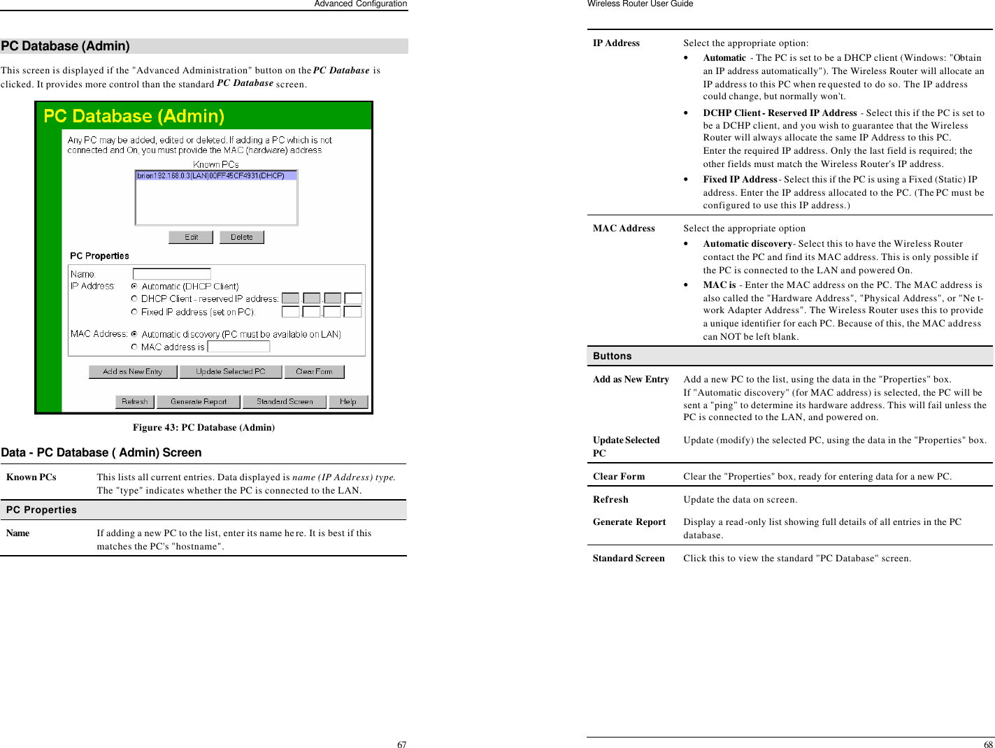
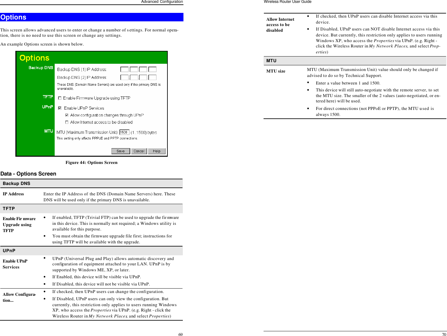
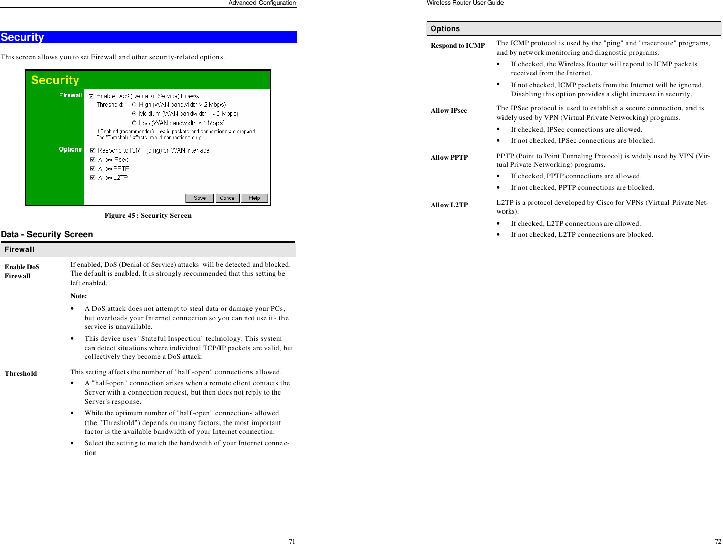
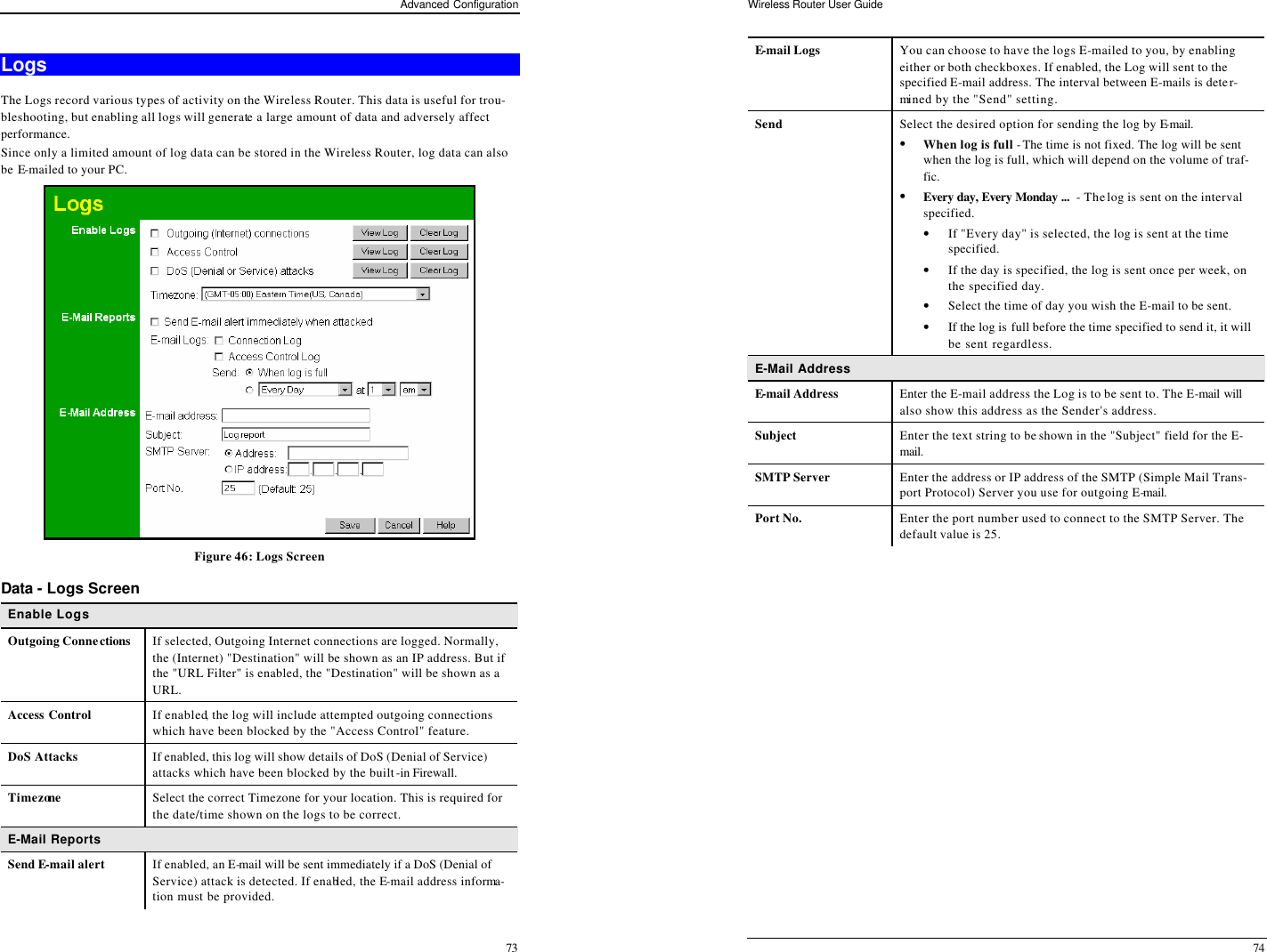
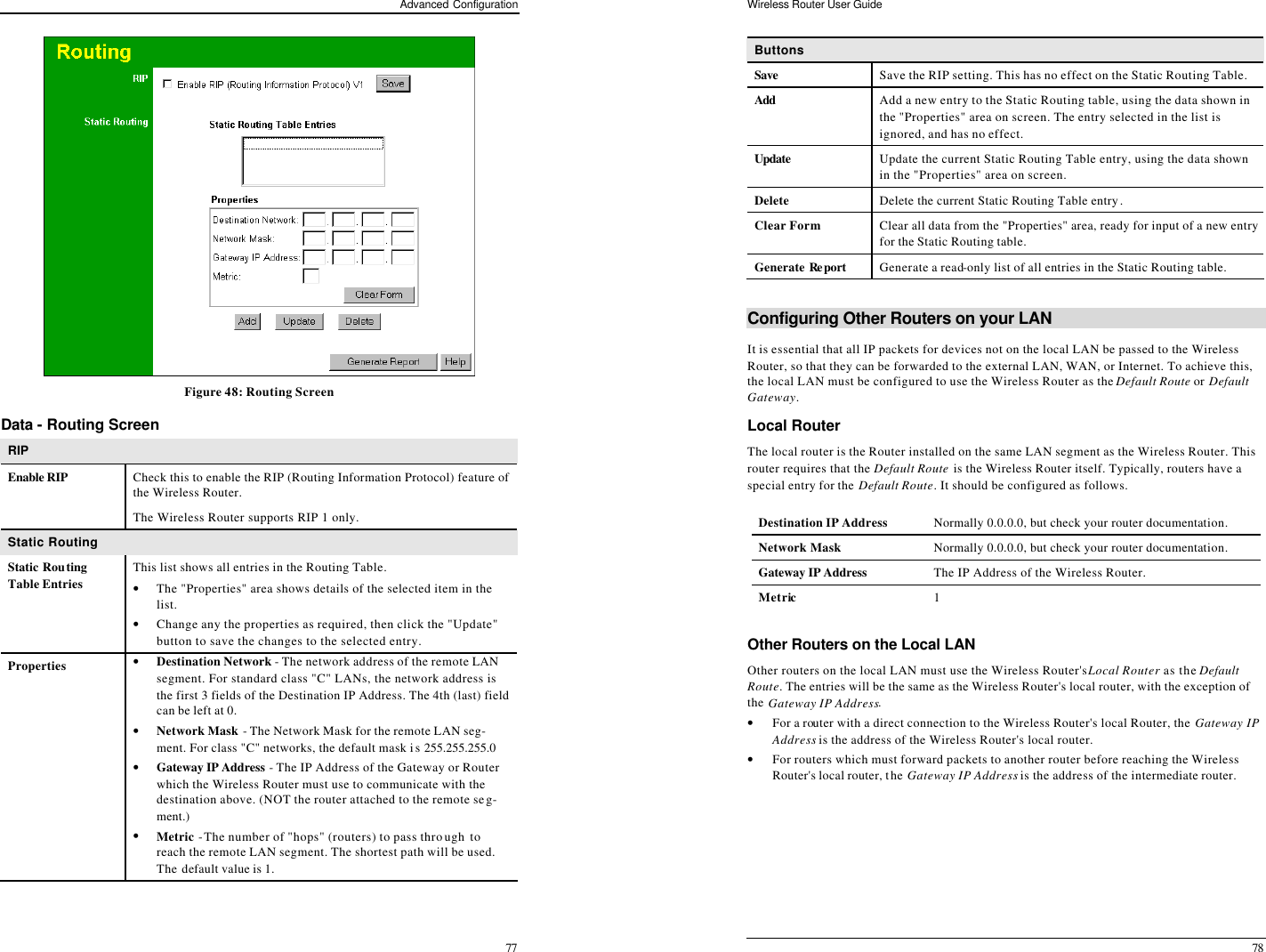
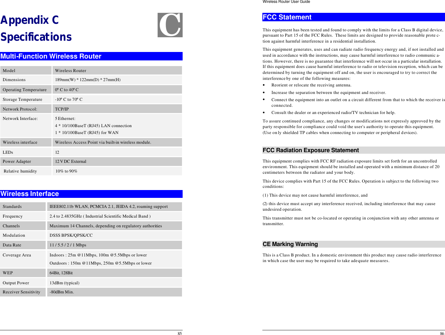
![Advanced Configuration 75 MAC Address The MAC (hardware) address is a low-level network identifier. It may be called "MAC Ad-dress", "Hardware Address", or "Physical Address". On a PC, this address is associated with the Network card or adapter. The address on the MAC Address screen is the address on the Internet (WAN port) interface, and has no effect on the LAN interface. • If your ISP asks for the "Network Adapter Address", "Physical Address", "Hardware Address", or "MAC Address" for the PC the DSL/Cable modem is connected to, provide this value. • If your ISP has already recorded a MAC address, you can change the address used by the Wireless Router to match the address recorded by your ISP. MAC Address Screen Select MAC Address from the Advanced menu to reach a screen like the example below. Figure 47: MAC address Screen Data - MAC address Screen MAC (hardware) Address The current MAC (hardware) address is displayed. If your ISP has recorded a Hardware Address, you can "spoof" that address by entering it in the address field. The hardware address consists of 12 characters, where each character is a digit (0..9) or a character between A and F. Buttons Default Inserts the default MAC address into the MAC address field. You must click "Save" to actually change the address used. Copy from PC Inserts the MAC address from your PC into the MAC address field. You must click "Save" to actually change the address used. Save Save your changes to the Wireless Router. Cancel Reverse any changes made since the last "Save". If the MAC address is changed, the Wireless Router must restart. Wireless Router User Guide 76 Routing Overview • If you don't have other Routers or Gateways on your LAN, you can ignore the "Routing" page completely. • If the Wireless Router is only acting as a Gateway for the local LAN segment, ignore the "Routing" page even if your LAN has other Routers. • If your LAN has a standard Router (e.g. Cisco) on your LAN, and the Wireless Router is to act as a Gateway for all LAN segments, enable RIP (Routing Information Protocol) and ig-nore the Static Routing table. • If your LAN has other Gateways and Routers, and you wish to control which LAN seg-ments use each Gateway, do NOT enable RIP (Routing Information Protocol). Configure the Static Routing table instead. (You also need to configure the other Routers.) • If using Windows 2000 Data center Server as a software Router, enable RIP on the Wireless Router, and ensure the following Windows 2000 settings are correct: • Open Routing and Remote Access • In the console tree, select Routing and Remote Access , [server name], IP Routing, RIP • In the "Details" pane, right-click the interface you want to configure for RIP version 2, and then click "Properties". • On the "General" tab, set Outgoing packet protocol to "RIP version 2 broadcast", and Incoming packet protocol to "RIP version 1 and 2". Routing Screen The routing table is accessed by the Routing link on the Advanced screen. Using this Screen Generally, you will use either RIP (Routing Information Protocol) OR the Static Routing Table, as explained above, although is it possible to use both methods simultaneously. Static Routing Table • If RIP is not used, an entry in the routing table is required for each LAN segment on your Network, other than the segment to which this device is attached. • The other Routers must also be configured. See Configuring Other Routers on your LAN later in this chapter for further details and an example.](https://usermanual.wiki/Sercomm/0K30/User-Guide-315551-Page-40.png)