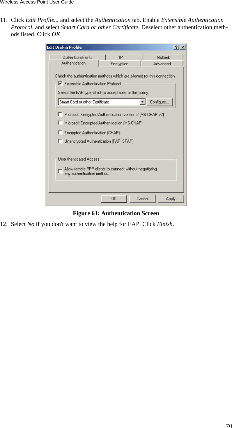
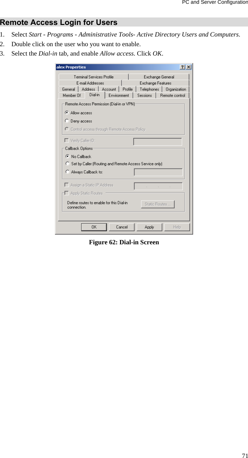
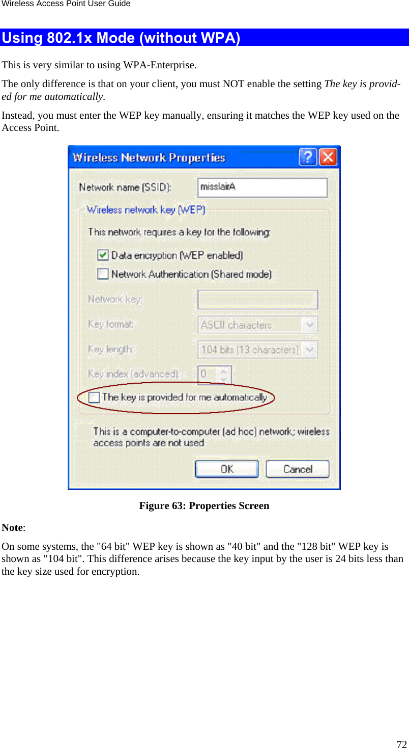
Sercomm AP221AI 11n Dual Band Wireless Access Point User Manual AP221AI User s Guide 20130424
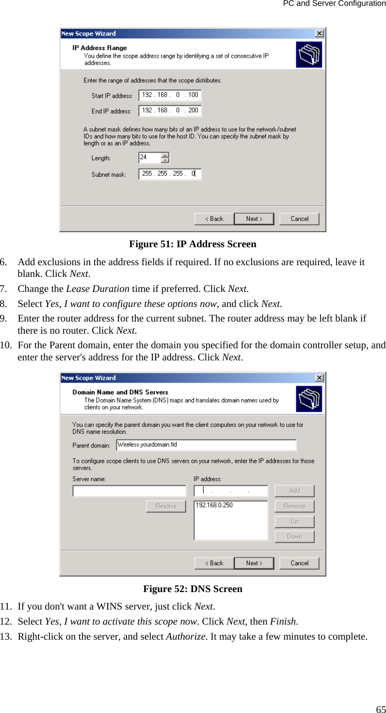
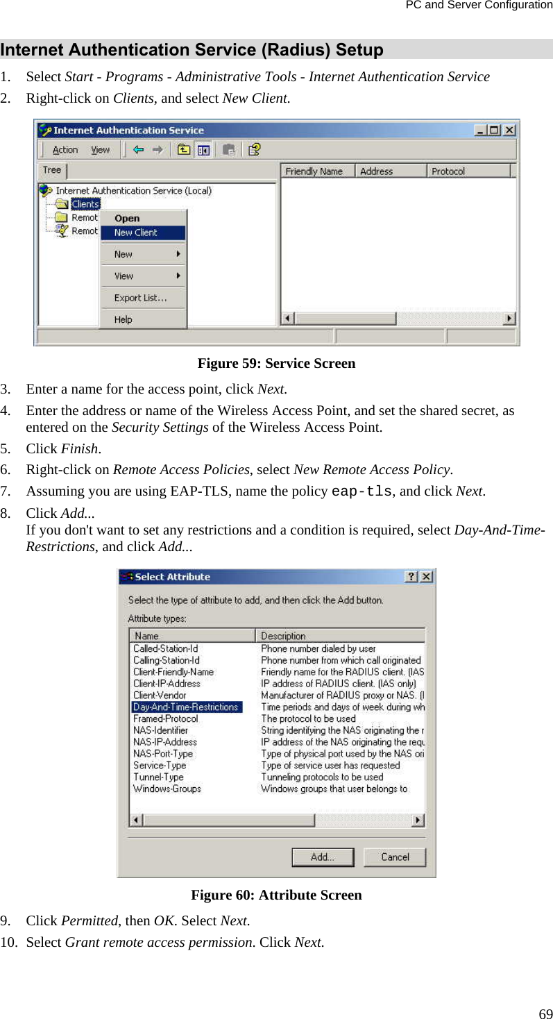
Sercomm Corporation 11n Dual Band Wireless Access Point AP221AI User s Guide 20130424
UserManual.wiki
>
Sercomm
>
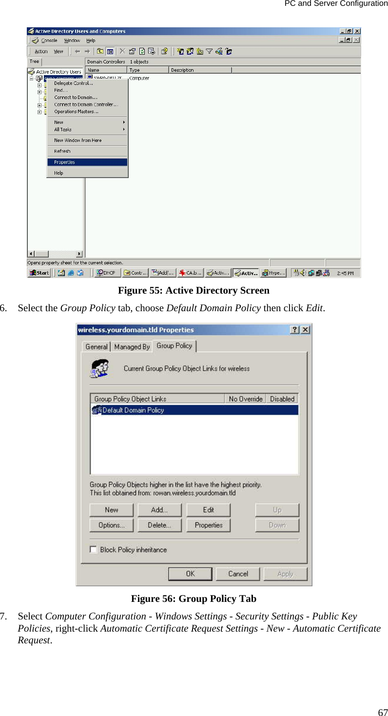
AP221AI User Manual
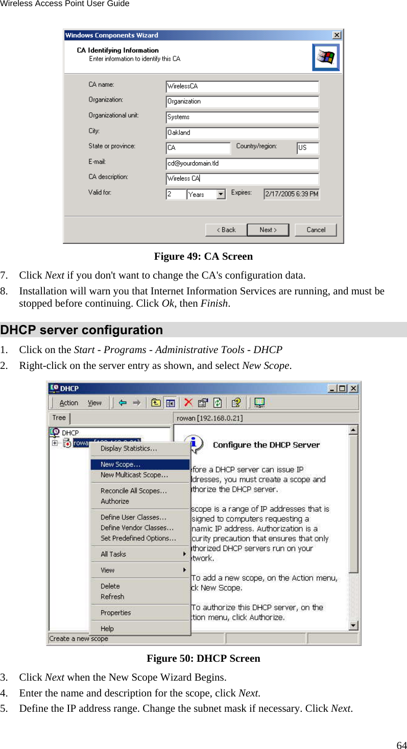
User Manual
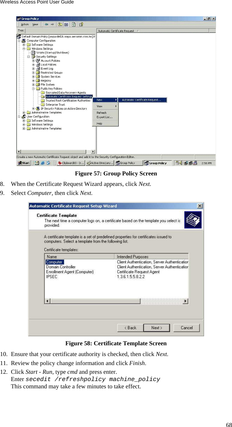
Navigation menu
Upload a User Manual
Namespaces
Wiki Guide
HTML
PDF
Info
Views
User Manual
Discussion / Help
Navigation


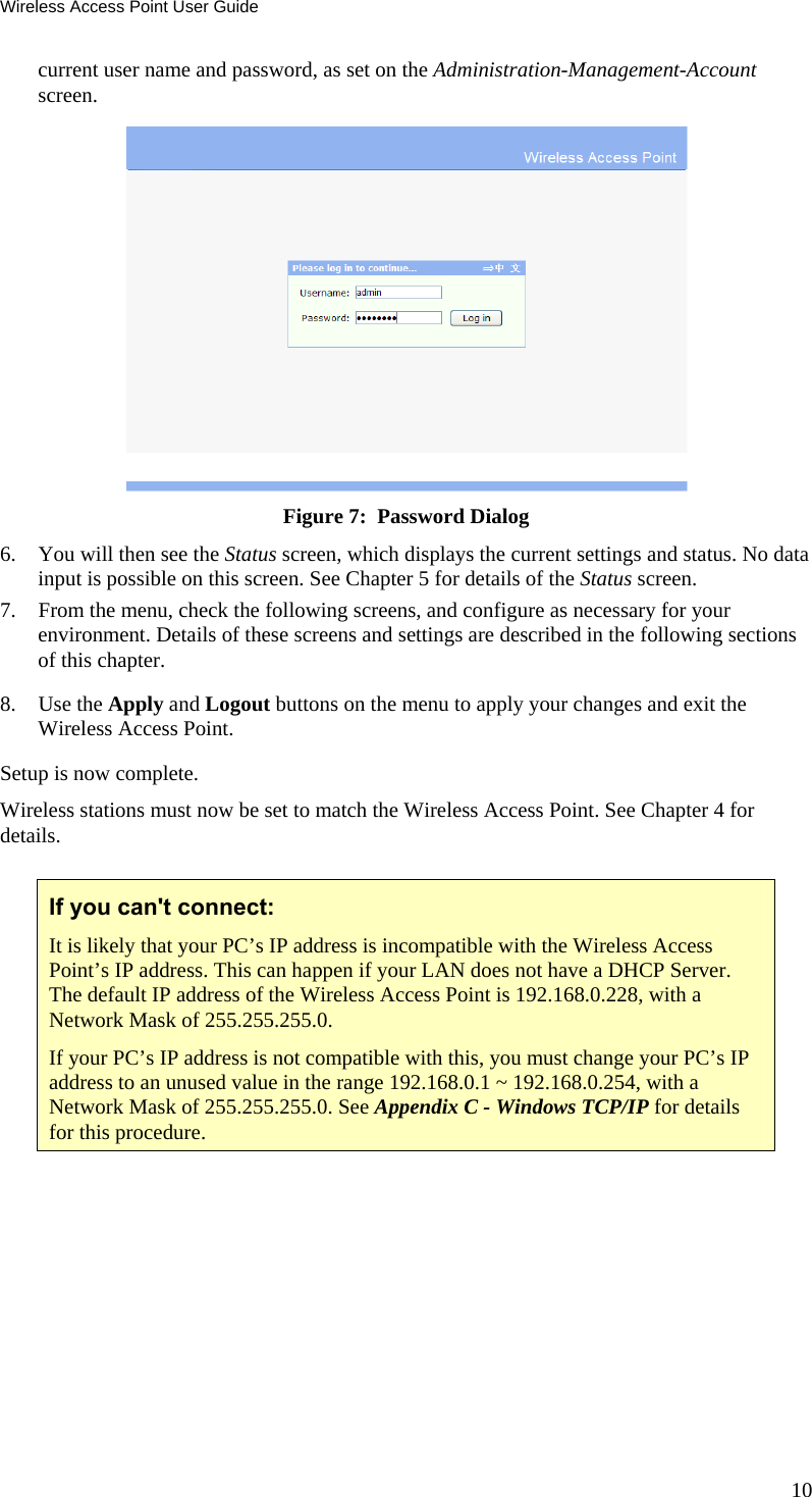
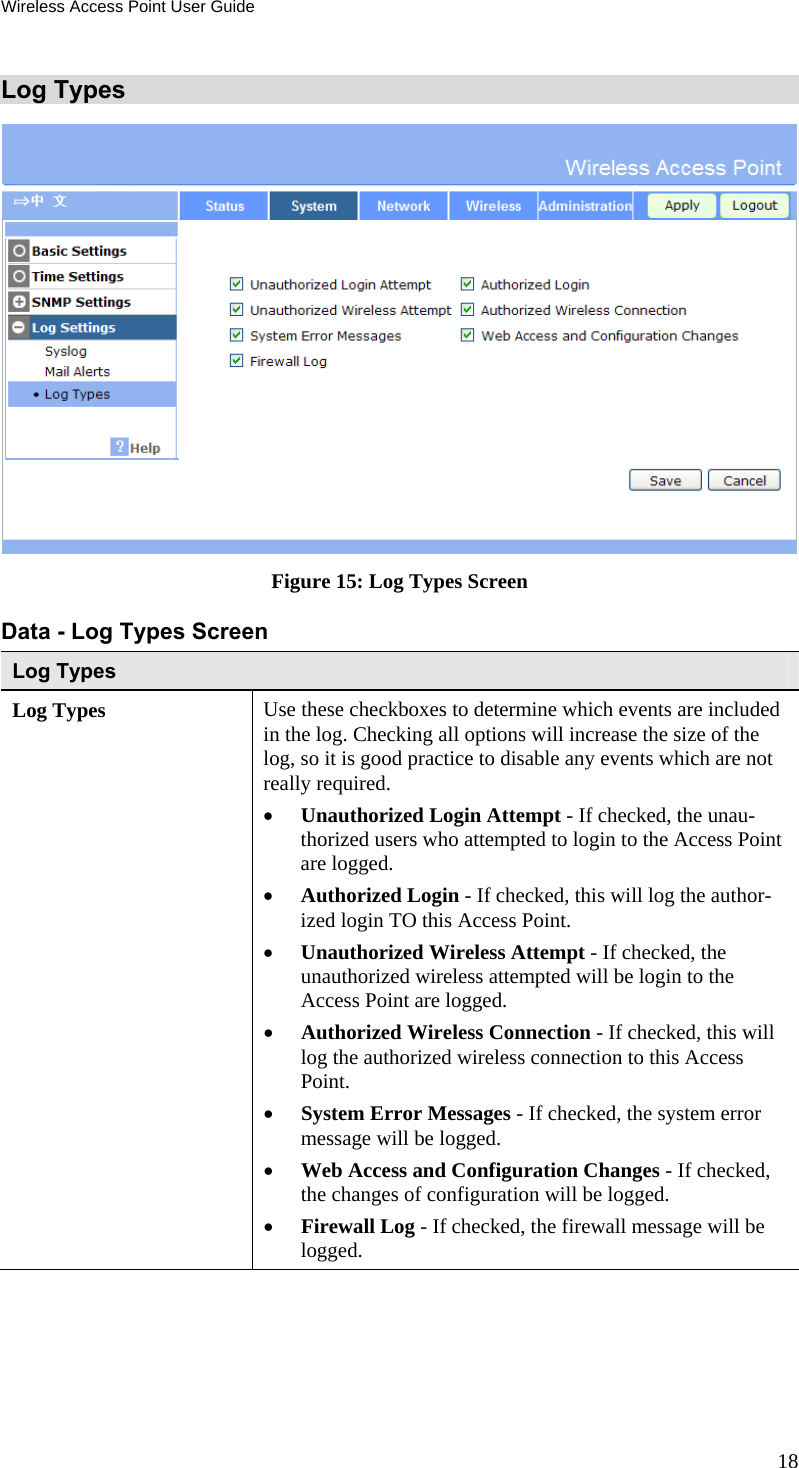
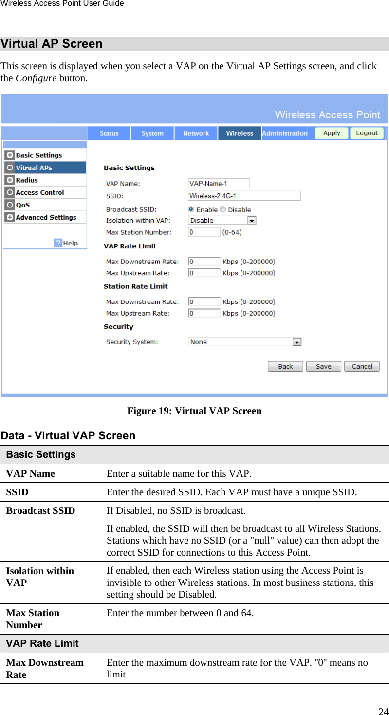
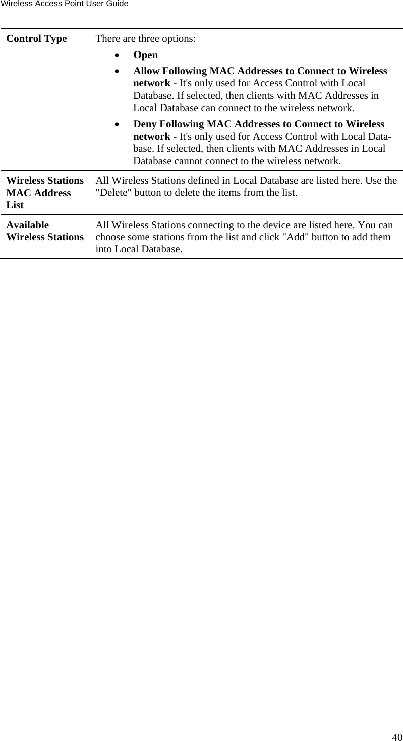
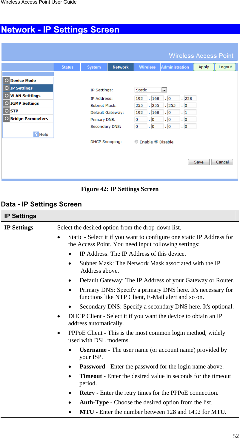
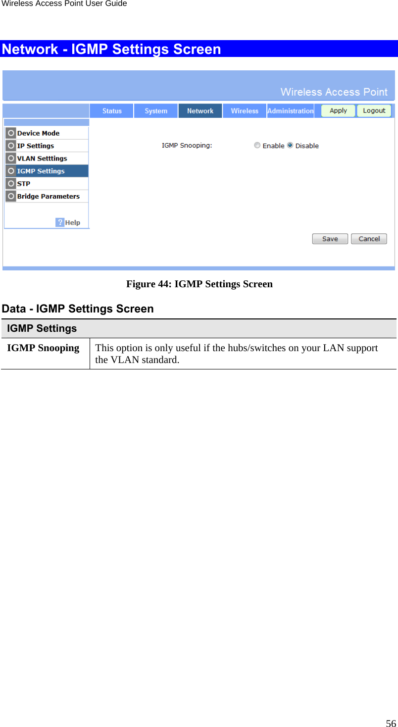
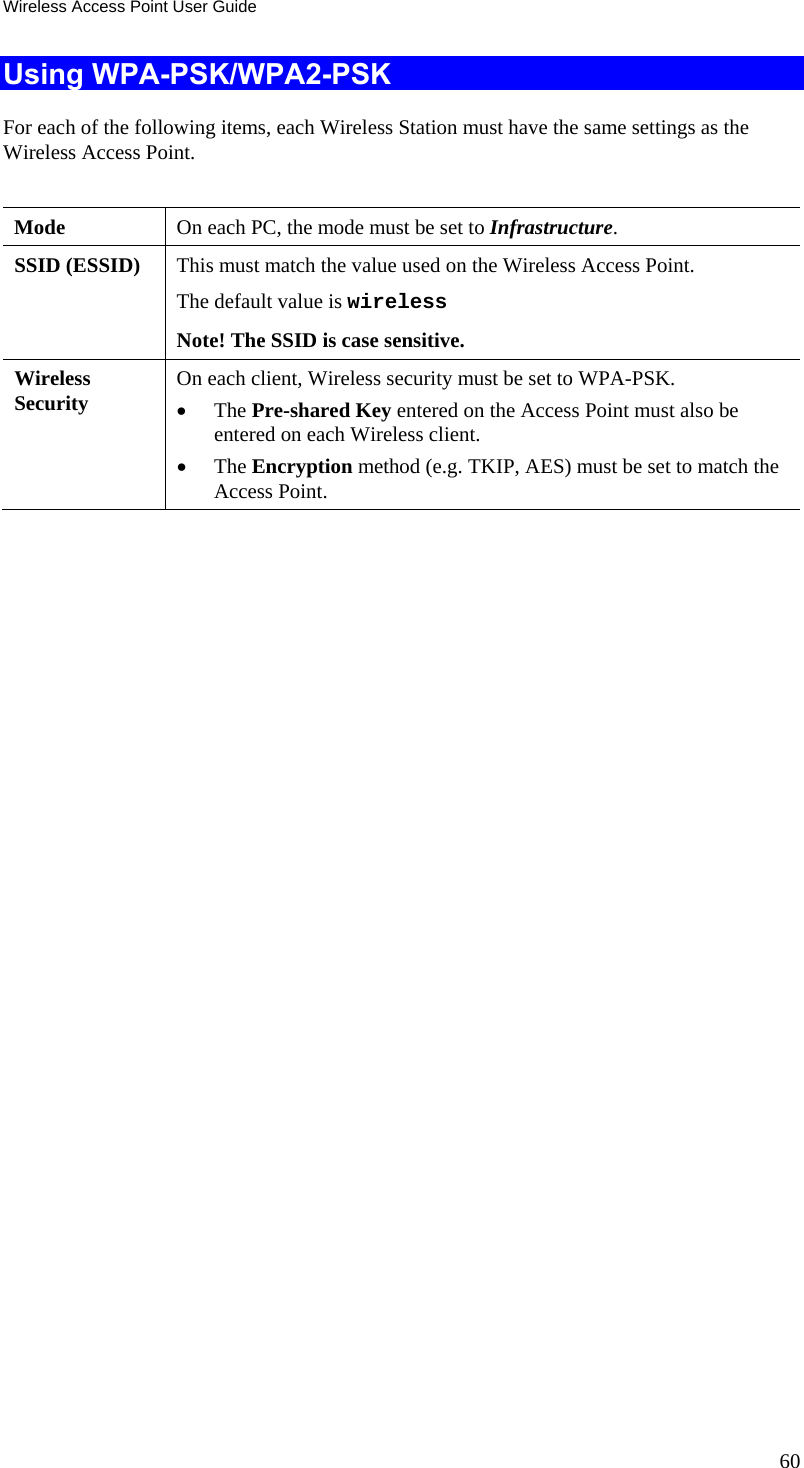
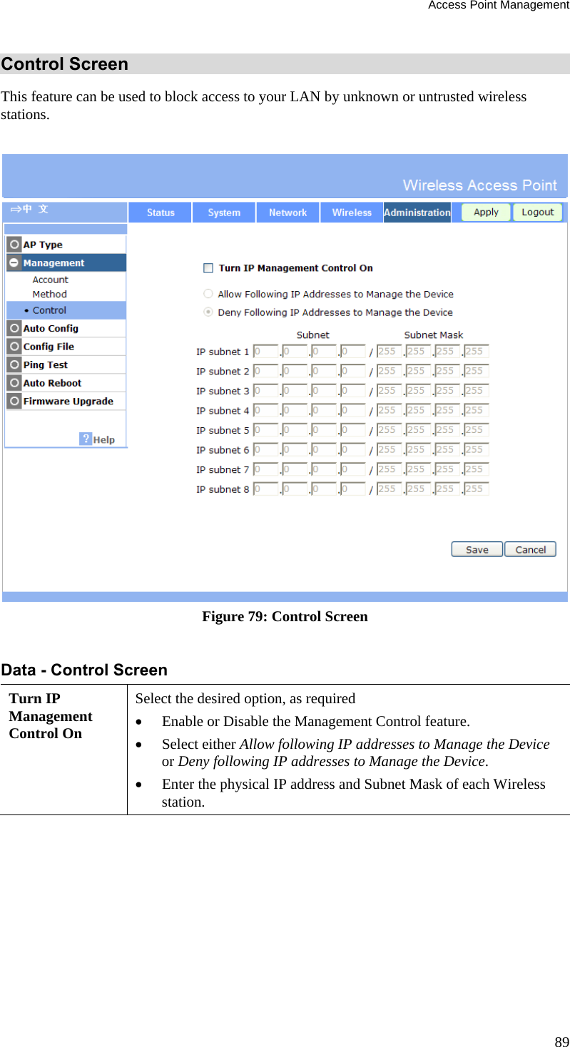
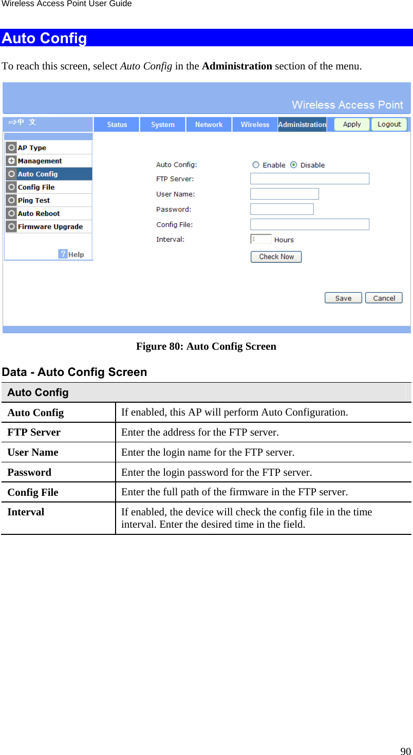
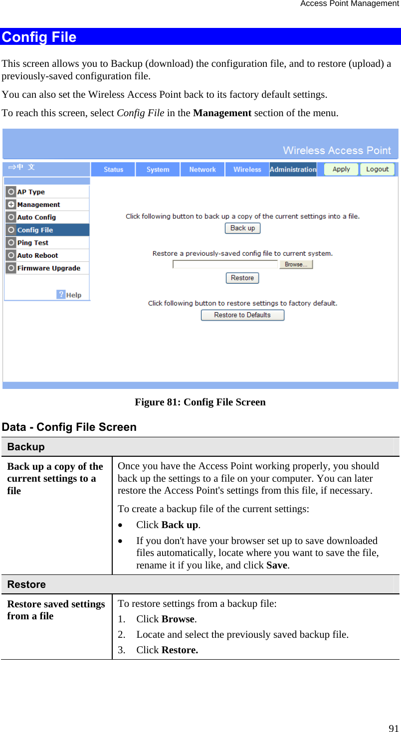
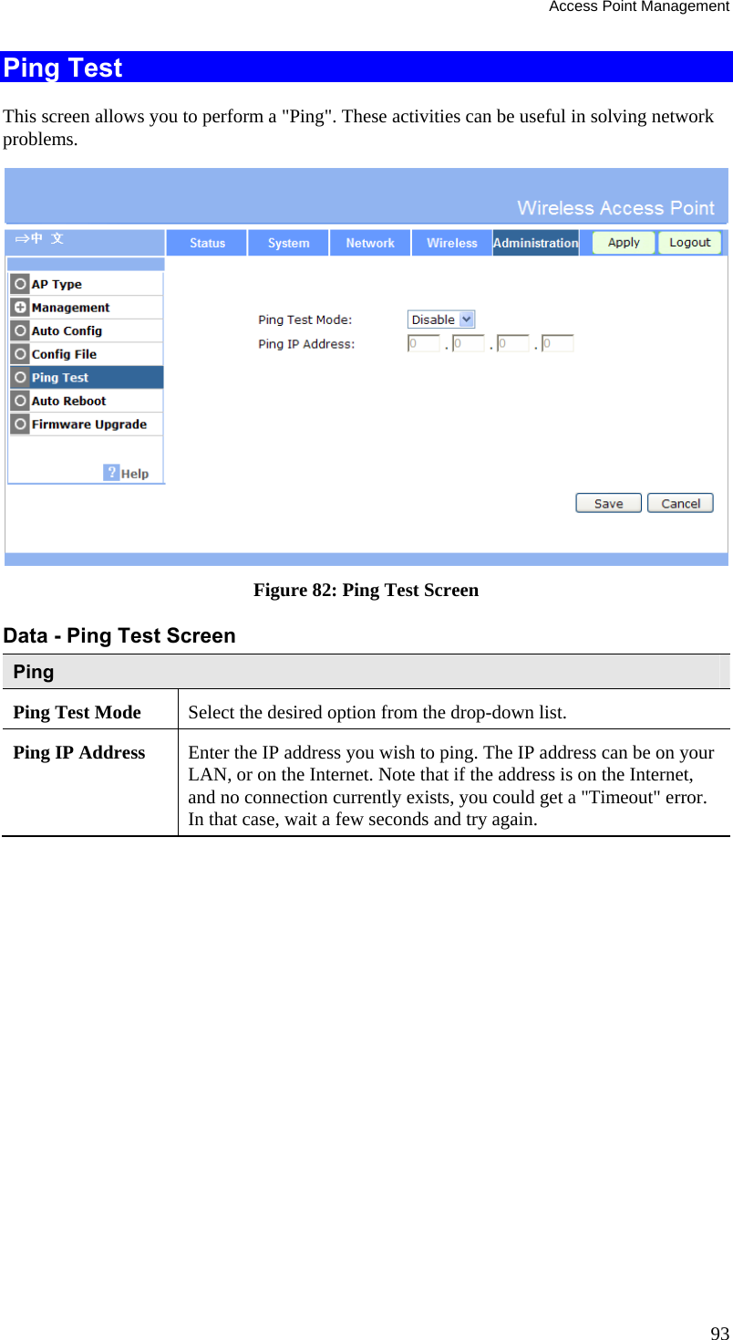
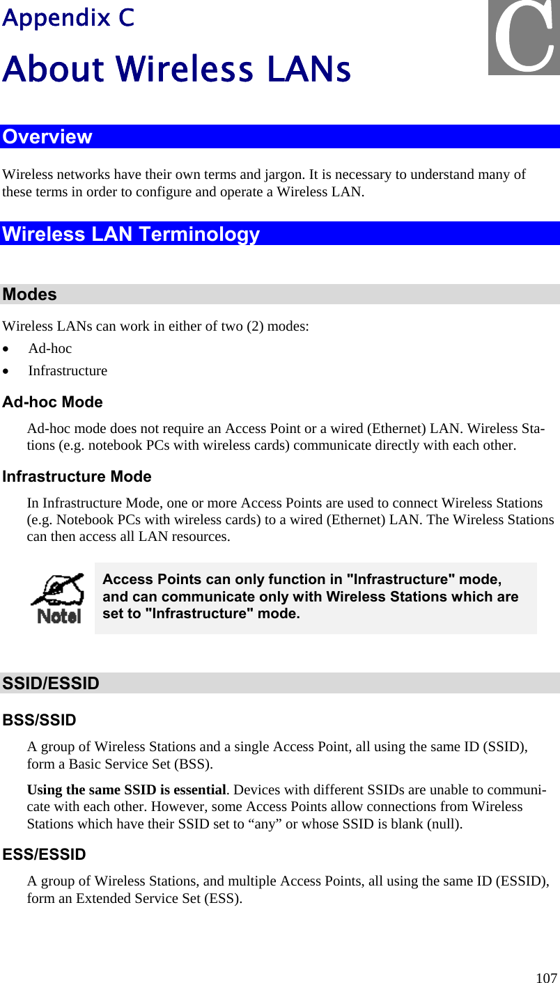
![Wireless Access Point User Guide 22 Figure 18: Virtual APs Settings Data - Virtual APs Settings Screen VAPs Wireless Radio Select the either Radio 1 or Radio 2 for the wireless feature. VAP List All available VAPs are listed. Up to 16 VAPs/Radios can be supported. For each VAP, the following data is displayed: * If displayed before the name of the VAP, this indicates the VAP is currently enabled. If not displayed, the VAP is currently disabled. VAP Name The current VAP name is displayed. [SSID] The current SSID associated with this VAP. Security System The current security system (e.g. WPA-PSK) is dis-played. Enable Button Enable the selected VAP. Configure Button Change the settings for the selected VAP. Disable Button Disable the selected VAP. Isolation Isolation among VAPs Select the desired option from the list. If this option is enabled, wireless clients using different VAPs (different SSIDs) are isolated from each other, so they will NOT be able to communi-cate with each other. They will still be able to communicate with other clients using the same profile, unless the "Wireless](https://usermanual.wiki/Sercomm/AP221AI/User-Guide-2211557-Page-26.png)