Sercomm DLC200SUS Digital Life Controller User Manual DLC200 QIG V1 0
Sercomm Corporation Digital Life Controller DLC200 QIG V1 0
Sercomm >
User Manual rev (2).pdf
i
DLC-200S
Digital Life Controller
User Guide

ii
Table of Contents
CHAPTER 1 INTRODUCTION .............................................................................................. 1
Features .............................................................................................................................. 1
LEDs ................................................................................................................................... 2
CHAPTER 2 INITIAL INSTALLATION............................................................................... 4
Requirements ..................................................................................................................... 4
Procedure ........................................................................................................................... 4
APPENDIX A SPECIFICATIONS .......................................................................................... 6
Digital Life Controller ....................................................................................................... 6
Regulatory Approvals ....................................................................................................... 6
Copyright 2014. All Rights Reserved.
Document Version: 1.0
All trademarks and trade names are the properties of their respective owners.

1
Chapter 1
Introduction
This Chapter provides an overview of the Controller's features and capabili-
ties.
Congratulations on the purchase of your new device. The Digital Life controller uses multiple
radios to control and manage appliances, lighting; remotely lock or unlock doors and other
security and automation services. In addition, the controller even includes 24-hour backup and
advanced diagnostics.
Ultimately, this device is designed for users to gain remote, wireless access to cameras, window
and door sensors, smoke detectors, thermostats and other appliance controls. A professional
initial installation is required.
Features
• NAND 4GB Flash
• DDR3 RAM 1GB
• One WAN port with RJ45 connector
• One LAN port with RJ45 connector (LAN is disable, for debug only)
• PoE (802.3at Type) Support
• Front Panel LEDs
• One button for turning off sounder
• 24-hour battery backup
• One Micro SD card slot (Optional)
• Internal antenna for 3G, WiFi, DECT, Z-Wave, ZigBee, One-way Radio and Two-way
Radio
1
2
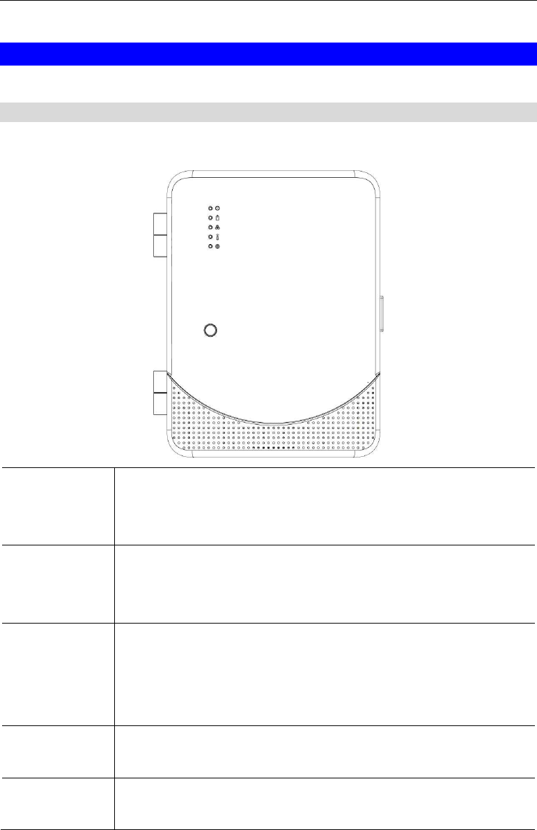
LEDs
Top-mounted LEDs
The device has five LEDs.
Power • On (Green) - Power On
• On (Red) - Power Failure
• Off - Power Off
Battery • On (Green) - The battery is installed
• On (Red) - The battery needs to be Replaced.
• Off – Battery not installed.
System • On (Green) - System is good
• On (Red) - There is a system problem
• On (Yellow) - The system is in Maintenance
• Flashing - Indicates Radio Frequency (RF) Jamming
Wireless
Broadband
• On (Green) - Wireless connection established.
• Off - No active connection on the corresponding LAN port.
Wireline
Broadband
• On (Green) - Wireline connection established.
• Off - No active connection on the WAN port.
3
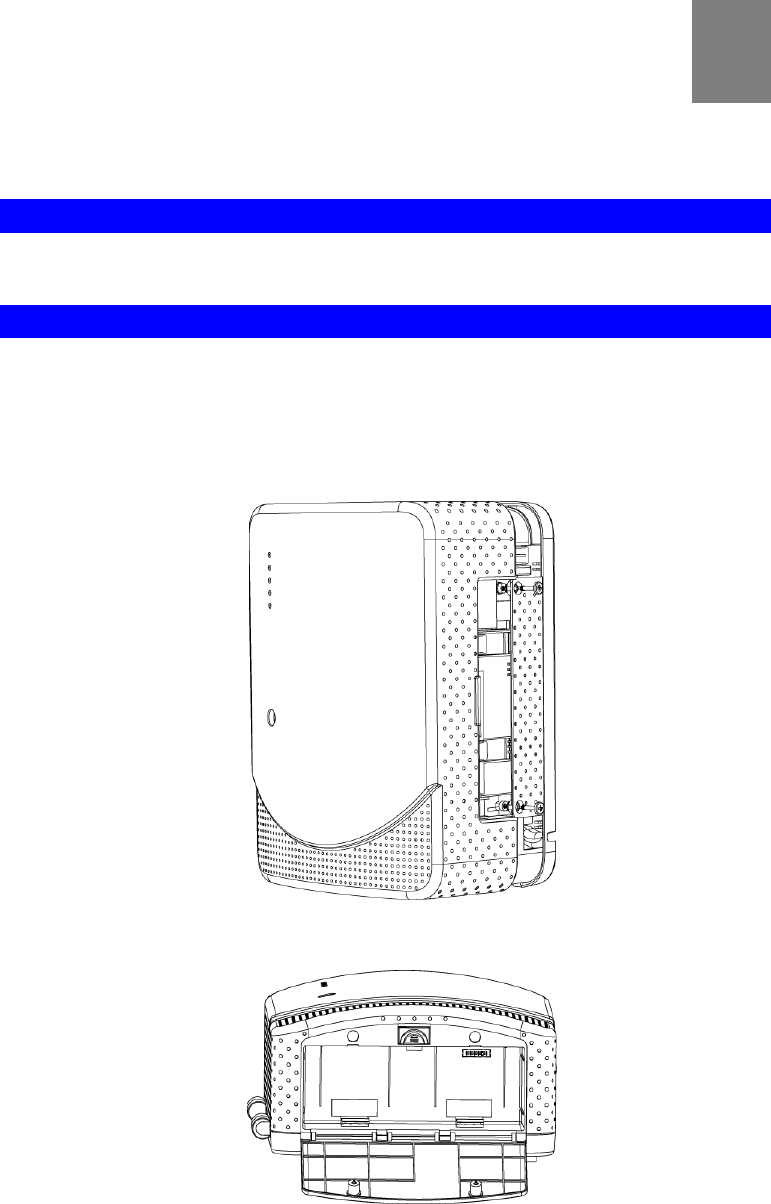
Rear Panel
LAN Port The standard Ethernet cable can provide the power to the device by
connecting the device to your router or PC.
WAN Port Connect this port to your ADSL connection.
Micro SD Card
(Optional)
Insert the SD card into the slot, if required.
SIM Card Slot Insert the SIM card for mobile broadband access.
4
Chapter 2
Initial Installation
This Chapter covers the software installation of the Controller.
Requirements
• Use standard 10/100BaseT network (UTP) cables with RJ45 connectors.
Procedure
1. Choose an Installation Site
Select a suitable place to install the Controller.
Note: You can open the front cover by removing the two screws with a screwdriver if re-
quired.
Note: Use a screwdriver to remove the two screws of the battery cover before installing the
battery.
2
5
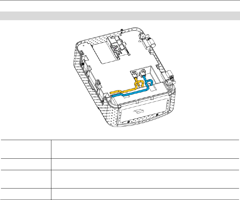
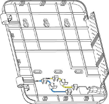
2. Connect Ethernet Cables
Route a standard Ethernet cable from the LAN port through the openings to connect to the
device.
Route a standard Ethernet cable from the WAN port through the openings to connect to the
ADSL router.
3. Check the LEDs
• The Power LED should be ON.
• The Wireless Broadband LED should be ON.
6
Appendix A
Specifications
Digital Life Controller
Model Digital Life Controller
Network Interface Two Ethernet 10/100BaseT (RJ45) Ports:
One RJ-45 for WAN
One RJ-45 for LAN (LAN is disable, for debug only)
Operating Temperature -10° C to 55° C
Storage Temperature -45° C to 85° C
Micro SD Card (Op-
tional)
One SD Card slot
Button 1
LEDs 5
Power Power Over Ethernet (PoE)
Battery Backup support
Regulatory Approvals
FCC Statement
This equipment generates, uses and can radiate radio frequency energy and, if not installed and
used in accordance with the instructions, may cause harmful interference to radio communica-
tions. However, there is no guarantee that interference will not occur in a particular installation.
If this equipment does cause harmful interference to radio or television reception, which can be
determined by turning the equipment off and on, the user is encouraged to try to correct the
interference by one of the following measures:
• Reorient or relocate the receiving antenna.
• Increase the separation between the equipment and receiver.
• Connect the equipment into an outlet on a circuit different from that to which the receiver
is connected.
• Consult the dealer or an experienced radio/TV technician for help.
To assure continued compliance, any changes or modifications not expressly approved by the
party responsible for compliance could void the user's authority to operate this equipment.
(Example - use only shielded interface cables when connecting to computer or peripheral
devices).
A

7
FCC Radiation Exposure Statement
This equipment complies with FCC RF radiation exposure limits set forth for an uncontrolled
environment. This equipment should be installed and operated with a minimum distance of 20
centimeters between the radiator and your body.
This device complies with Part 15 of the FCC Rules. Operation is subject to the following two
conditions:
(1) This device may not cause harmful interference, and
(2) This device must accept any interference received, including interference that may cause
undesired operation.
This transmitter must not be co-located or operating in conjunction with any other antenna or
transmitter.
CE Approvals
The Controller and the Ethernet Controller meet the
guidelines of the European Union and comply with the 99/5/EEC and RTTE 99/5EG directives,
including the following standards:
• EN 50131
This is a Class B product. In a domestic environment this product may cause radio interference
in which case the user may be required to take adequate measures.
This product is UL and cUL certified and comply with UL985/UL1023/UL1637/UL60950
Information Technology Equipment applicable requirement.
25