Sercomm IP802SM 3 in 1 AP User Manual FullManual

Sercomm Corporation 3 in 1 AP FullManual

Contents

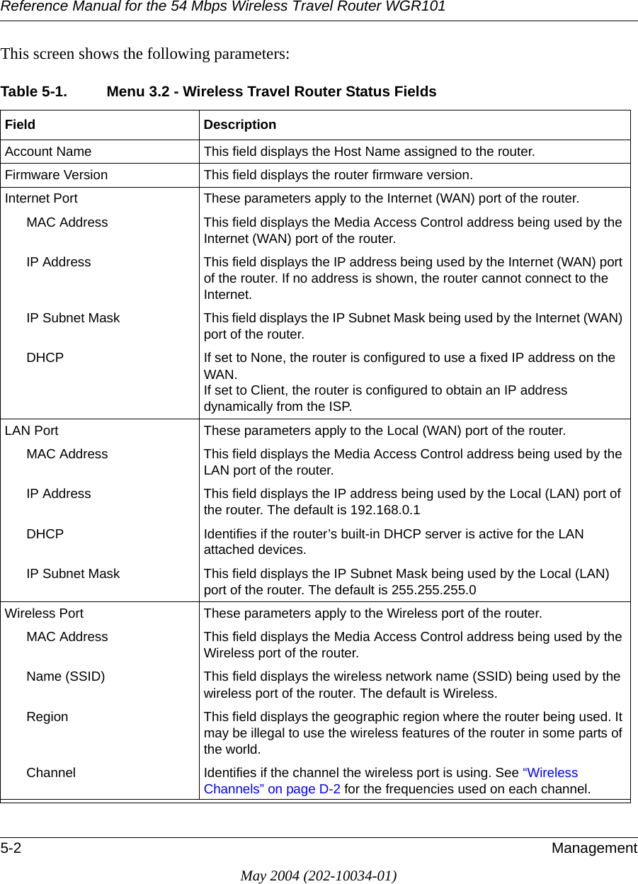
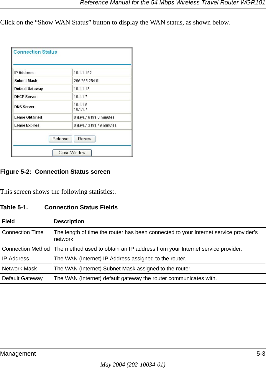
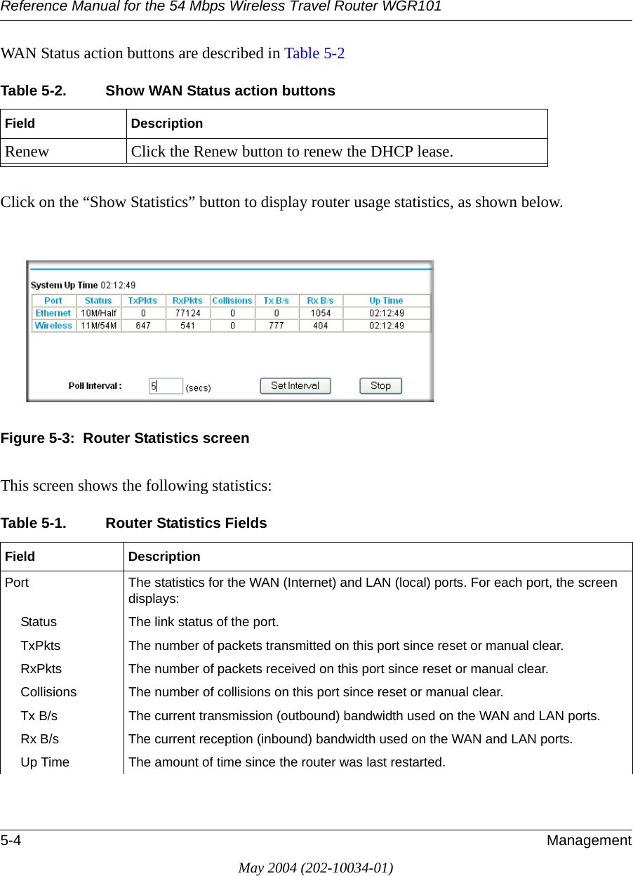
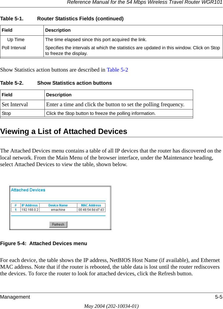
Users Manual Part 2 Revised

About This Manual 1May 2004 (202-10034-01)Chapter 1 About This ManualThis chapter describes the intended audience, scope, conventions, and formats of this manual.Audience, Scope, Conventions, and FormatsThis reference manual assumes that the reader has basic to intermediate computer and Internet skills. However, basic computer network, Internet, firewall, and VPN technologies tutorial information is provided in the Appendices and on the Netgear website.This guide uses the following typographical conventions:This guide uses the following formats to highlight special messages:This manual is written for the WGR101 wireless travel router according to these specifications.:Table 1-1. Typographical Conventionsitalics Emphasis, books, CDs, URL namesbold times roman User inputcourier font Screen text, file and server names, extensions, commands, IP addressesNote: This format is used to highlight information of importance or special interest.Table 1-2. Manual ScopeProduct Version 54 Mbps Wireless Travel Router WGR101 Manual Publication Date May 2004Note: Product updates are available on the NETGEAR Web site at  www.netgear.com/support/main.asp.
Reference Manual for the 54 Mbps Wireless Travel Router WGR1012About This ManualMay 2004 (202-10034-01)How to Use This ManualThe HTML version of this manual includes a variety of navigation features as well as links to PDF versions of the full manual and individual chapters.Figure 1 -1:  HTML version of this manual1. Left pane. Use the left pane to view the Contents, Index, Search, and Favorites tabs. To view the HTML version of the manual, you must have a version 4 or later browser with JavaScript enabled.2. Toolbar buttons. Use the toolbar buttons across the top to navigate, print pages, and more.The Show in Contents button locates the current topic in the Contents tab.Previous/Next buttons display the previous or next topic.The PDF button links to a PDF version of the full manual.The Print button prints the current topic. Click this button when a step-by-step procedure is displayed to send the entire procedure to your printer. You do not have to worry about specifying the correct range of pages.3. Right pane. Use the right pane to view the contents of the manual. Also, each page of the manual includes a  link at the top right which links to a PDF file containing just the currently selected chapter of the manual.123
Reference Manual for the 54 Mbps Wireless Travel Router WGR101About This Manual 3May 2004 (202-10034-01)How to Print this ManualTo print this manual you can choose one of the following several options, according to your needs.•Printing a “How To” Sequence of Steps in the HTML View.   Use the Print button  on the upper right of the toolbar to print the currently displayed topic. Use this button when a step-by-step procedure is displayed to send the entire procedure to your printer. You do not have to worry about specifying the correct range of pages. •Printing a Chapter.   Use the   link at the top right of any page.– Click “PDF of This Chapter” link at the top right of any page in the chapter you want to print. The PDF version of the chapter you were viewing opens in a browser window. Note:  Your computer must have the free Adobe Acrobat reader installed in order to view and print PDF files. The Acrobat reader is available on the Adobe web site at  http://www.adobe.com.– Click the print icon in the upper left of the window. Tip: If your printer supports printing two pages on a single sheet of paper, you can save paper and printer ink by selecting this feature.•Printing the Full Manual.   Use the PDF button in the toolbar at the top right of the browser window.– Click the PDF button   on the upper right of the toolbar. The PDF version of the chapter you were viewing opens in a browser window. – Click the print icon in the upper left of the window. Tip: If your printer supports printing two pages on a single sheet of paper, you can save paper and printer ink by selecting this feature.
Reference Manual for the 54 Mbps Wireless Travel Router WGR1014About This ManualMay 2004 (202-10034-01)
Introduction 2-1May 2004 (202-10034-01)Chapter 2 IntroductionCongratulations on your purchase of the NETGEAR® 54 Mbps Wireless Travel Router WGR101 . The WGR101 wireless travel router provides connection for multiple computers to the Internet through an RJ45 wall slot or an external broadband access device (such as a cable modem) that is normally intended for use by a single computer. This chapter describes the features of the NETGEAR 54 Mbps Wireless Travel Router WGR101 .Key FeaturesThe 54 Mbps Wireless Travel Router WGR101  with 4-port switch connects one or more wireless computers to the Internet through an RJ45 slot, router, or cable modem.With minimum setup, you can install and use the router within minutes.The WGR101 wireless travel router provides the following features:• 802.11g wireless networking, with the ability to operate in 802.11g-only, or 802.11b+g modes.• Easy, web-based setup for installation and management.• Ethernet connection to an RJ45 wall slot, router, or cable modem.• Extensive Protocol Support.• Login capability.• Front panel LEDs for easy monitoring of status and activity.• Flash memory for firmware upgrade.Note: This manual provides information on the complete features as of the date of publication. Earlier versions of this product may not have all the features presented in this manual. Check the NETGEAR Web site at www.netgear.com/support/main.asp where you will find product firmware updates for your WGR101.
Reference Manual for the 54 Mbps Wireless Travel Router WGR1012-2 IntroductionMay 2004 (202-10034-01)802.11g Wireless NetworkingThe WGR101 wireless travel router includes an 802.11g wireless access point, providing continuous, high-speed 54 Mbps access between your wireless and Ethernet devices. The access point provides:• 802.11g wireless networking at up to 54 Mbps.• 802.11g wireless networking, with the ability to operate in 802.11g-only, 802.11b-only, or 802.11g and b modes, providing backwards compatibility with 802.11b devices or dedicating the wireless network to the higher bandwidth 802.11g devices.• 64-bit and 128-bit WEP encryption security.• WEP keys can be generated manually or by passphrase.• WPA-PSK support. Support for Wi-Fi Protected Access (WPA) data encryption which provides strong data encryption and authentication based on a pre-shared key.• Wireless access can be restricted by MAC address.• Wireless network name broadcast can be turned off so that only devices that have the network name (SSID) can connect.SecurityThe WGR101 wireless travel router is equipped with several features designed to maintain security, as described in this section.• Computers Hidden by NAT NAT opens a temporary path to the Internet for requests originating from the local network. Requests originating from outside the LAN are discarded, preventing users outside the LAN from finding and directly accessing the computers on the LAN.Autosensing Ethernet Connections with Auto Uplink With its internal 8-port 10/100 switch, the WGR101 can connect to either a 10 Mbps standard Ethernet network or a 100 Mbps Fast Ethernet network. Both the LAN and WAN interfaces are autosensing and capable of full-duplex or half-duplex operation.
Reference Manual for the 54 Mbps Wireless Travel Router WGR101Introduction 2-3May 2004 (202-10034-01)The router incorporates Auto UplinkTM technology. Each Ethernet port will automatically sense whether the Ethernet cable plugged into the port should have a ‘normal’ connection such as to a computer or an ‘uplink’ connection such as to a switch or hub. That port will then configure itself to the correct configuration. This feature also eliminates the need to worry about crossover cables, as Auto Uplink will accommodate either type of cable to make the right connection.Extensive Protocol SupportThe WGR101 wireless travel router supports the Transmission Control Protocol/Internet Protocol  (TCP/IP) and Routing Information Protocol (RIP). For further information about TCP/IP, refer to Appendix B, “Network, Routing, Firewall, and Basics.”• IP Address Sharing by NAT The WGR101 wireless travel router allows several networked computers to share an Internet account using only a single IP address, which may be statically or dynamically assigned by your Internet service provider (ISP). This technique, known as NAT, allows the use of an inexpensive single-user ISP account.• Automatic Configuration of Attached computers by DHCP The WGR101 wireless travel router dynamically assigns network configuration information, including IP, gateway, and domain name server (DNS) addresses, to attached computers on the LAN using the Dynamic Host Configuration Protocol (DHCP). This feature greatly simplifies configuration of computers on your local network.• DNS Proxy When DHCP is enabled and no DNS addresses are specified, the router provides its own address as a DNS server to the attached computers. The router obtains actual DNS addresses from the ISP during connection setup and forwards DNS requests from the LAN.Easy Installation and ManagementYou can install, configure, and operate the 54 Mbps Wireless Travel Router WGR101  within minutes after connecting it to the network. The following features simplify installation and management tasks:• Browser-based management Browser-based configuration allows you to easily configure your router from almost any type of personal computer, such as Windows, Macintosh, or Linux. Online help documentation is built into the browser-based Web Management Interface.
Reference Manual for the 54 Mbps Wireless Travel Router WGR1012-4 IntroductionMay 2004 (202-10034-01)• Firmware Update The WGR101 wireless travel router can be updated if a newer version of firmware is available. This lets you take advantage of product enhancements for your WGR101 as soon as they become available.• Visual monitoring The WGR101 wireless travel router’s front panel LEDs provide an easy way to monitor its status and activity.Maintenance and SupportNETGEAR offers the following features to help you maximize your use of the WGR101 wireless travel router:• Flash memory for firmware upgrade• Free technical support seven days a week, twenty-four hours a dayPackage ContentsThe product package should contain the following items:• 54 Mbps Wireless Travel Router WGR101 .•AC power adapter.• Category 5 (CAT5) Ethernet cable.•NETGEAR 54 Mbps Wireless Travel Router WGR101 Resource CD (230-10081-01), including:— This guide.— Application Notes and other helpful information.•.• Registration, Warranty Card, and Support Information Card.If any of the parts are incorrect, missing, or damaged, contact your NETGEAR dealer. Keep the carton, including the original packing materials, in case you need to return the router for repair.
Reference Manual for the 54 Mbps Wireless Travel Router WGR101Introduction 2-5May 2004 (202-10034-01)The Router’s SwitchFigure 2-1:  WGR101, Side ViewThe side of the WGR101 Travel Router has a four-position switch. It ships in position 1, which is used when connecting to the router as a single user. The switch position functions are as follows:•Switch position 1: single wireless computer only access, no configuration access •Switch position 2: configuration and multiple wireless computer access•Switch position 3: configuration only via Ethernet or wirelessly connected computer•Switch position 4: unused at this timeFor information about changing the switch position for multiple computers to share the WGR101 Travel Router, or to configure WEP security, refer to “Setup Options Overview” in Chapter 3.3WITCHINPOSITION
Reference Manual for the 54 Mbps Wireless Travel Router WGR1012-6 IntroductionMay 2004 (202-10034-01)The Router’s Front PanelThe front panel of the WGR101 wireless travel router contains the status lights described below. Figure 2-2:  WGR101 Front PanelYou can use the status lights to verify connections. Viewed from left to right, the table below describes the lights on the front panel of the router. Table 2-1. Status Light DescriptionsLabel Activity DescriptionPowerOn Green SolidOff Power is supplied to the router.Power is not supplied to the router.WirelessOn Green SolidBlink GreenOffThe router has located a wireless connection and is ready for use.Data is being transmitted or received.No wireless connection is available.Ethernet On Green SolidBlink GreenOffEthernet is connected.Data is being transmitted or received.No link is detected on this port.Ethernet PortWireless PortPower
Reference Manual for the 54 Mbps Wireless Travel Router WGR101Introduction 2-7May 2004 (202-10034-01)The Router’s Rear PanelThe rear panel of the router is shown below.Viewed from left to right, the rear panel contains the following features:Figure 2-3:  WGR101 Rear Panel• Reset: This push button can reset the router to the last settings, or reset to the factory default settings.• Ethernet: This port is used for Internet (WAN) connection via an RJ45 wall slot, router, or cable modem. It is also used as a LAN port to connect the router to a local computer.• Power: The AC power adapter outlet.If you want to: Hold Reset button down Release Reset buttonReset After power-on When power LED is still onReset to factory After power-on for about five seconds When the Power LED is flashingPowerEthernetResetWAN/LAN PortButton
Reference Manual for the 54 Mbps Wireless Travel Router WGR1012-8 IntroductionMay 2004 (202-10034-01)
Connecting the Router to the Internet 3-1May 2004 (202-10034-01)Chapter 3Connecting the Router to the InternetThis chapter describes how to set up the router on your local area network (LAN) and connect to the Internet. You will find out how to configure your 54 Mbps Wireless Travel Router WGR101  for Internet access.Prepare to Install Your Wireless Travel RouterBefore proceeding with the wireless travel router installation, familiarize yourself with the contents of the NETGEAR 54 Mbps Wireless Travel Router WGR101 Resource CD (230-10081-01), especially this manual and the animated tutorials.For the initial setup of your router, you will need to connect a computer to the router. This computer has to be set to automatically get its TCP/IP configuration from the router via DHCP.Note: For help with DHCP configuration, please use the Windows TCP/IP Configuration Tutorials on the NETGEAR 54 Mbps Wireless Travel Router WGR101 Resource CD (230-10081-01), or refer to Appendix C, “Preparing Your Network.
Reference Manual for the 54 Mbps Wireless Travel Router WGR1013-2 Connecting the Router to the InternetMay 2004 (202-10034-01)Setup Options OverviewLocate the recommended setup for the WGR101 Travel Router on the chart below.Figure 3-1:  Single User ScenariosType of Use Recommended Setup Application Usage Switch Position on the Unit CommentOne computer access, casual use, no sensitive data.Quick Installation (No WEP security) Exclusive access for the first computer to select this SSID.1(default setting) No configuration required.One computer working in a setting such as a hotel room where others may abruptly connect to this SSID. Or, working with sensitive data and needing to encrypt and use a secure wireless connection.Single user with WEP security. NETGEAR recommends this setup.Exclusive access and reserves the connection for you with matching WEP keys.First, change to position 3 to configure WEP security, then change to position 1 to connect as a single user with WEP security.See instructions in the User manual for configuring WEP security settings.3WITCHPOSITION,!.
Reference Manual for the 54 Mbps Wireless Travel Router WGR101Connecting the Router to the Internet 3-3May 2004 (202-10034-01)Figure 3-2:  Multiple User ScenariosType of Use Recommended Setup Application Usage Switch Position on the Unit CommentMultiple computers, casual use, no sensitive data.Quick Installation (No WEP Security), Multiple user switch positionShared among computers that use this SSID.2 No configuration required.Multiple computers working where others may accidentally connect to this SSID. Working with sensitive data.Installation with WEP Security, multiple user switch position.Shared access, and reserves connection for computers with matching SSID and WEP keys.First, change to 3 to configure WEP security settings; then change to position 2 to connect as a single user with WEP securitySee instructions below for configuring WEP security settings.3WITCHPOSITION,!.
Reference Manual for the 54 Mbps Wireless Travel Router WGR1013-4 Connecting the Router to the InternetMay 2004 (202-10034-01)Quick Installation: No Router Configuration or WEP SecurityThese instructions assume the following:• You will connect the WGR101 wireless travel router to an RJ45 wall slot in the office or hotel, or a broadband router at home• You will not use wireless WEP security• One or more wireless computers will connect to the WGR101 wireless travel router. Use WEP (“Basic Wireless Security WEP Configuration” on page 3-8) to protect sensitive data. 1. First, install the Travel Routera. Connect an Ethernet cable to the port on the WGR101 Travel Router. If you are traveling, connect the other end of the cable to an RJ45 slot in the wall. If you are home or in an office, connect the other end of the cable to a switch, router, or cable modem with a broadband Internet connection. Figure 3-3:  Switch position 3b. The WGR101 wireless travel router ships with the switch in position 1 for a single user. If multiple computers will use the travel router, change the switch position to 2.c. Connect the power cord to the Travel Router and plug it into an outlet. The Power LED lights up. The Travel Router automatically broadcasts a wireless signal.2. Now, configure your wireless computer(s)a. On your computer, set NETGEAR-TRAVEL as the SSID for each computer that will use the Travel Router. Tip: If you are typing the SSID, note that it is case sensitive and must match the WGR101 Travel Router SSID exactly. b. The Wireless LED on the Travel Router is on when a wireless connection is available. This LED flashes during data transfer. Position 1: Single UserPosition 2: Multiple Users
Reference Manual for the 54 Mbps Wireless Travel Router WGR101Connecting the Router to the Internet 3-5May 2004 (202-10034-01)How to Log in to the Wireless Travel RouterYou can always connect to the router to change its settings. These two switch settings enable you to log in:•Switch position 1: single wireless computer only access, no configuration access •Switch position 2: configuration and multiple wireless computer access as explained in “Network Configuration” on page 6-1.•Switch position 3: configuration only via Ethernet or wirelessly connected computer as explained in “Basic Wireless Security WEP Configuration” on page 3-8 below•Switch position 4: unused at this timeFollow these procedures to log in to the wireless travel router.Figure 3-4:  Switch position 31. Set the switch to position 3.2. Connect the power cord to the wireless travel router and plug it into an outlet. The Power LED lights up. Warning: Be sure to power on the wireless travel router before connecting the cable from the computer. If you do not observe this sequence, you computer may time out and fail to connect. 3WITCHINPOSITION
Reference Manual for the 54 Mbps Wireless Travel Router WGR1013-6 Connecting the Router to the InternetMay 2004 (202-10034-01)Figure 3-5:  Computer connected via Ethernet cable to WGR101 wireless travel router3. Connect an Ethernet cable to the wireless travel router.Check the status lights and verify the following:Power: When you first turn on the router, the power light blinks during the diagnostic self test, then turns solid green.  Ethernet: The Ethernet port light on the wireless travel router should be lit. If not, make sure the Ethernet cable is securely attached. Wireless: The Wireless light should be lit. If the Wireless light is not lit, see the Basic Setup Troubleshooting Tips below. 4. Open a Web browser such as Internet Explorer on the computer to connect to the wireless travel router. The wireless travel router will automatically connecting to the browser.A login window like the one shown below opens:Figure 3-6:  Login window3WITCHPOSITION
Reference Manual for the 54 Mbps Wireless Travel Router WGR101Connecting the Router to the Internet 3-7May 2004 (202-10034-01)When prompted, enter admin for the router user name and password for the router password, both in lower case letters. The WGR101 wireless travel router and display the home page as shown in below.Figure 3-7: Switch position 3 login result: WGR101 wireless settings pageThe browser will then display the WGR101 wireless settings page.You can set the wireless security options on this page. Use the procedure below for basic wireless WEP configuration, or see “Wireless Configuration” on page 4-1 for a full explanation of all the wireless options.If you do not click Logout, the wireless travel router will wait 5 minutes after there is no activity before it automatically logs you out.
Reference Manual for the 54 Mbps Wireless Travel Router WGR1013-8 Connecting the Router to the InternetMay 2004 (202-10034-01)Basic Wireless Security WEP ConfigurationThe procedure provides instructions for basic wireless security configuration for single or multiple users. For full instructions on setting the wireless settings, see “Wireless Configuration” on page 4-1.1. LOG IN TO THE WGR101 WIRELESS TRAVEL ROUTER (SEE PAGE 3-5)The WGR101 wireless travel router and display the wireless settings page as shown in below.Figure 3-8: Login result: WGR101 home pageNote: If you did not connect to the router, verify that your computer is set up for DHCP. For help with this, please see the animated tutorials on the CD or Appendix C, “Preparing Your Network.2. CUSTOMIZE THE WEP WIRELESS SECURITY SETTINGSa. The Wireless Settings page shows NETGEAR-TRAVEL as the Name (SSID).b. In the Region field, choose the country where you are located.
Reference Manual for the 54 Mbps Wireless Travel Router WGR101Connecting the Router to the Internet 3-9May 2004 (202-10034-01)c. Select the Encryption Strength (128 bit or 64 bit) for Security Encryption (WEP).d. Enter a Passphrase for the Security Encryption (WEP) key. After configuration the Passphrase can be used to configure NETGEAR equipment instead of entering the WEP number.e. Click Generate to create the WEP key. If using a Passphrase, write it down. Otherwise, write down the WEP number. This number is needed to configure your computer to work with the Travel Router.f. Click Apply to use the WEP keys.3. CONFIGURE YOUR WIRELESS COMPUTER(S)a. Set NETGEAR-TRAVEL as the SSID for each computer that will use the Travel Router. Tip: If you are typing the SSID, note that it is case sensitive and must match the WGR101 Travel Router SSID exactly. b. The Wireless LED on the Travel Router is on when a wireless connection is available. This LED flashes during data transfer. Basic Setup Troubleshooting TipsHere are some tips for correcting simple problems that prevent you from connecting to the Internet or connecting to the wireless travel router. Make sure the network settings of the computer are correct. • LAN and wirelessly connected computers must be configured to obtain an IP address automatically via DHCP. For instructions on how to do this, please see the animated tutorials on the NETGEAR 54 Mbps Wireless Travel Router WGR101 Resource CD (230-10081-01) or Appendix C, “Preparing Your Network.”• The switch on the Travel router must be in position 1 for a single user or in position 2 for multiple users.• If your hotel asks you to configure your PC with a fixed IP and you want to use the Travel Router with multiple computers, you may need to adjust the Basic Settings. See “Network Configuration” on page 6-1.• Do not connect the Travel Router directly to a DSL modem. Connect the Travel Router to a switch or another router that is connected to the DSL modem.
Reference Manual for the 54 Mbps Wireless Travel Router WGR1013-10 Connecting the Router to the InternetMay 2004 (202-10034-01)• If you are using the Travel Router with multiple users, it works as a secondary router. The primary router may be set up to block parameters such as ftp or TCPIP. Check the settings on the primary router.• The Travel Router default IP setting is 192.168.0.1 with the user name of admin and the password of password. If you connect the Travel Router to another router that also is set as 192.168.0.x, you must change the WGR101 wireless travel router setting so that it does not conflict.Check the router status lights to verify correct router operation. • During normal operation, the Travel Router Power LED is solid green, and the Ethernet and Wireless LEDS are solid green, or flashing during data transfer.• If the Power light does not turn solid green within 2 minutes after turning on the router, reset the router according to the instructions in “Restoring the Default Configuration and Password” on page 7-5.• If the Wireless light does not come on, verify that the wireless feature is turned on according to the instructions in “Restoring the Default Configuration and Password” on page 7-5.Check the router status lights to verify correct router operation. • During normal operation, the Travel Router Power LED is solid green, and the Ethernet and Wireless LEDS are solid green, or flashing during data transfer.• If the Power light does not turn solid green within 2 minutes after turning on the router, reset the router according to the instructions in “Restoring the Default Configuration and Password” on page 7-5.• If the Wireless light does not come on, verify that the wireless feature is turned on according to the instructions in “Restoring the Default Configuration and Password” on page 7-5.• If the status lights are normal and there is no Internet connection, use an Ethernet cable to connect the PC directly to the RJ45 slot in the wall. If you are able to connect to the Internet, this indicates a problem with the wireless connection or the SSID.Make sure the wireless settings in the computer and router are set correctly. • The Wireless Network Name (SSID) and WEP settings of the router and wireless computer must match exactly. The SSID is case sensitive.• If you are a single user and are not using WEP security, another user may be connected to this SSID. Repower the Travel Router to clear the connection, and retry. If the problem persists, configure the router to use WEP to reserve the connection for you.• When working in the default single user configuration, only one connection to the Internet is allowed.
Reference Manual for the 54 Mbps Wireless Travel Router WGR101Connecting the Router to the Internet 3-11May 2004 (202-10034-01)Note: Product updates and support information are available on the NETGEAR Web site at www.netgear.com/support/main.asp.
Reference Manual for the 54 Mbps Wireless Travel Router WGR1013-12 Connecting the Router to the InternetMay 2004 (202-10034-01)
Wireless Configuration 4-1May 2004 (202-10034-01)Chapter 4 Wireless ConfigurationThis chapter describes how to configure the wireless features of your WGR101 wireless travel router. In planning your wireless network, you should consider the level of security required. You should also select the physical placement of your firewall in order to maximize the network speed. For further information on wireless networking, refer to in Appendix D, “Wireless Networking Basics.Observe Performance, Placement, and Range GuidelinesThe operating distance or range of your wireless connection can vary significantly based on the physical placement of the wireless firewall. The latency, data throughput performance, and notebook power consumption of wireless adapters also vary depending on your configuration choices.For best results, place your firewall:• Near the center of the area in which your computers will operate.• In an elevated location such as a high shelf where the wirelessly connected computers have line-of-sight access (even if through walls).• Away from sources of interference, such as computers, microwaves, and 2.4 GHz cordless phones.• Away from large metal surfaces.The time it takes to establish a wireless connection can vary depending on both your security settings and placement. WEP connections can take slightly longer to establish. Also, WEP encryption can consume more battery power on a notebook computer.Note: Failure to follow these guidelines can result in significant performance degradation or inability to wirelessly connect to the router. For complete range/performance specifications, please see Appendix A, “Technical Specifications.”
Reference Manual for the 54 Mbps Wireless Travel Router WGR1014-2 Wireless ConfigurationMay 2004 (202-10034-01)Implement Appropriate Wireless Security Unlike wired network data, your wireless data transmissions can be received well beyond your walls by anyone with a compatible adapter. For this reason, use the security features of your wireless equipment. The WGR101 wireless travel router provides highly effective security features which are covered in detail in this chapter. Deploy the security features appropriate to your needs.Figure 4-1:  Wireless data security optionsThere are several ways you can enhance the security of you wireless network.•Restrict Access Based on MAC Address. You can restrict access to only trusted computers o that unknown computers cannot wirelessly connect to the WGR101. MAC address filtering adds an obstacle against unwanted access to your network, but the data broadcast over the wireless link is fully exposed. •Turn Off the Broadcast of the Wireless Network Name SSID. If you disable broadcast of the SSID, only devices that have the correct SSID can connect. This nullifies the wireless network ‘discovery’ feature of some products such as Windows XP, but the data is still fully exposed to a determined snoop using specialized test equipment like wireless sniffers.•WEP. Wired Equivalent Privacy (WEP) data encryption provides data security. WEP Shared Key authentication and WEP data encryption will block all but the most determined eavesdropper. Note: Indoors, computers can connect over 802.11b/g wireless networks at ranges of up to 300 feet. Such distances can allow for others outside of your immediate area to access your network.:LUHOHVV 'DWD6HFXULW\ 2SWLRQV5DQJH 8S WR  )RRW 5DGLXV /PEN 3YSTEM %ASY BUT NO SECURITY -!# !CCESS ,IST .O DATA SECURITY 7%0 3ECURITY BUT SOME PERFORMANCE IMPACT
Reference Manual for the 54 Mbps Wireless Travel Router WGR101Wireless Configuration 4-3May 2004 (202-10034-01)•Turn Off the Wired LAN. If you disable the wireless LAN, wireless devices cannot communicate with the router at all. You might choose to turn off the wireless the LAN when you are away and the others in the household all use wired connections.Understanding Wireless SettingsTo configure the Wireless settings of your firewall, click the Wireless link in the main menu of the browser interface. The Wireless Settings menu will appear, as shown below.Figure 4-2:  Wireless Settings page
Reference Manual for the 54 Mbps Wireless Travel Router WGR1014-4 Wireless ConfigurationMay 2004 (202-10034-01)•Name (SSID). The SSID is also known as the wireless network name. Enter a value of up to 32 alphanumeric characters. In a setting where there is more than one wireless network, different wireless network names provide a means for separating the traffic. Any device you want to participate in a particular wireless network will need to use this SSID for that network. The WGR101 default SSID is: NETGEAR.•Region. This field identifies the region where the WGR101 can be used. It may not be legal to operate the wireless features of the wireless travel router in a region other than one of those identified in this field.•Channel. This field determines which operating frequency will be used. It should not be necessary to change the wireless channel unless you notice interference problems with another nearby access point. For more information on the wireless channel frequencies please refer to “Wireless Channels” on page D-2.•Mode. This field determines which data communications protocol will be used. You can select “g only,” “b only,” or “g and b.” “g only” dedicates the WGR101 to communicating with the higher bandwidth 802.11g wireless devices exclusively. “b only” dedicates the WGR101 to communicating with the higher bandwidth 802.11b wireless devices exclusively. The “g and b” mode provides backward compatibility with the slower 802.11b wireless devices while still enabling 802.11g communications. •Enable Wireless Access Point. If you disable the wireless access point, wireless devices cannot connect to the WGR101. •Allow Broadcast of Name (SSID). If you disable broadcast of the SSID, only devices that have the correct SSID can connect. Disabling SSID broadcast nullifies the wireless network ‘discovery’ feature of some products such as Windows XP.•Wireless Station Access List. When the Trusted PCs Only radio button is selected, the WGR101 checks the MAC address of the wireless station and only allows connections to computers identified on the trusted computers list. •Security Encryption. These options are the wireless security features you can enable. The table below identifies the various basic wireless security options. A full explanation of these standards is available in Appendix D, “Wireless Networking Basics.
Reference Manual for the 54 Mbps Wireless Travel Router WGR101Wireless Configuration 4-5May 2004 (202-10034-01)Table 4-1. Basic Wireless Security OptionsField  DescriptionAutomatic No wireless security.WEP WEP offers the following options:• Open SystemWith Open Network Authentication and 64- or 128-bit WEP Data Encryption, the WGR101 does perform 64- or 128-bit data encryption but does not perform any authentication. • Shared KeyShared Key authentication encrypts the SSID and data.Choose the Encryption Strength (64- or 128-bit data encryption). Manually enter the key values or enter a word or group of printable characters in the Passphrase box. Manually entered keys are case sensitive but passphrase characters are not case sensitive. Note: Not all wireless adapter configuration utilities support passphrase key generation.•Auto
Reference Manual for the 54 Mbps Wireless Travel Router WGR1014-6 Wireless ConfigurationMay 2004 (202-10034-01)Information to Gather Before Changing Basic Wireless SettingsBefore customizing your wireless settings, print this form and record the following information. If you are working with an existing wireless network, the person who set up or is responsible for the network will be able to provide this information. Otherwise, you will choose the settings for your wireless network. Either way, record the settings for your wireless network in the spaces below.•Wireless Network Name (SSID): ______________________________ The SSID, identifies the wireless network. You can use up to 32 alphanumeric characters. The SSID is case sensitive. The SSID in the wireless adapter card must match the SSID of the wireless travel router. In some configuration utilities (such as in Windows XP), the term “wireless network name” is used instead of SSID. •If WEP Authentication is Used. Circle one: Open System, Shared Key, or Auto. Note: If you select Shared Key, the other devices in the network will not connect unless they are set to Shared Key as well and are configured with the correct key.–WEP Encryption key size. Choose one: 64-bit or 128-bit. Again, the encryption key size must be the same for the wireless adapters and the wireless travel router.–Data Encryption (WEP) Keys. There are two methods for creating WEP data encryption keys. Whichever method you use, record the key values in the spaces below.•Passphrase method. ______________________________ These characters are case sensitive. Enter a word or group of printable characters and click the Generate Keys button. Not all wireless devices support the passphrase method.•Manual method. These values are not case sensitive. For 64-bit WEP, enter 10 hex digits (any combination of 0-9 or a-f). For 128-bit WEP, enter 26 hex digits.Key 1: ___________________________________ Key 2: ___________________________________ Key 3: ___________________________________ Key 4: ___________________________________ Use the procedures described in the following sections to configure the WGR101. Store this information in a safe place.
Reference Manual for the 54 Mbps Wireless Travel Router WGR101Wireless Configuration 4-7May 2004 (202-10034-01)Default Factory SettingsWhen you first receive your WGR101, the default factory settings are shown below. You can restore these defaults with the Factory Default Restore button on the rear panel. After you install the WGR101 wireless travel router, use the procedures below to customize any of the settings to better meet your networking needs.How to Set Up and Test Basic Wireless ConnectivityFollow the instructions below to set up and test basic wireless connectivity. Once you have established basic wireless connectivity, you can enable security settings appropriate to your needs.1. Log in to the WGR101 firewall at its default LAN address of http://192.168.0.1 with its default user name of admin and default password of password, or using whatever LAN address and password you have set up.2. Click Wireless Settings in the main menu of the WGR101 firewall.3. Choose a suitable descriptive name for the wireless network name (SSID). In the SSID box, enter a value of up to 32 alphanumeric characters. The default SSID is NETGEAR.FEATURE DEFAULT FACTORY SETTINGSWireless Access Point EnabledWireless Access List (MAC Filtering) All wireless stations allowedSSID broadcast  EnabledSSID  NETGEAR11b/g RF Channel 11Mode g and bAuthentication Type AutomaticWEP DisabledNote: If you use a wireless computer to configure WPA settings, you will be disconnected when you click Apply. Reconfigure your wireless adapter to match the new settings or access the wireless travel router from a wired computer to make any further changes.
Reference Manual for the 54 Mbps Wireless Travel Router WGR1014-8 Wireless ConfigurationMay 2004 (202-10034-01)Note: The SSID is case sensitive; NETGEAR is not the same as nETgear. Also, the SSID of any wireless access adapters must match the SSID you configure in the 54 Mbps Wireless Travel Router WGR101 . If they do not match, you will not get a wireless connection to the WGR101.4. Set the Region. Select the region in which the wireless interface will operate. 5. Set the Channel. The default channel is 11.This field determines which operating frequency will be used. It should not be necessary to change the wireless channel unless you notice interference problems with another nearby wireless router or access point. Select a channel that is not being used by any other wireless networks within several hundred feet of your firewall. For more information on the wireless channel frequencies please refer to “Wireless Channels” on page D-2. 6. For initial configuration and test, leave the Wireless Card Access List set to “Everyone” and the Encryption Strength set to “Disabled.” 7. Click Apply to save your changes.8. Configure and test your computers for wireless connectivity.Program the wireless adapter of your computers to have the same SSID and channel that you configured in the router. Check that they have a wireless link and are able to obtain an IP address by DHCP from the firewall.Warning: The Network Name (SSID) is case sensitive. If NETGEAR is the Network Name (SSID) in your wireless travel router, you must enter NETGEAR in your computer's wireless settings. Entering nETgear will not work.Once your computers have basic wireless connectivity to the firewall, then you can configure the advanced wireless security functions of the firewall.How to Configure WEPTo configure WEP data encryption, follow these steps:Note: If you are configuring the firewall from a wireless computer and you change the firewall’s SSID, channel, or security settings, you will lose your wireless connection when you click on Apply. You must then change the wireless settings of your computer to match the firewall’s new settings.
Reference Manual for the 54 Mbps Wireless Travel Router WGR101Wireless Configuration 4-9May 2004 (202-10034-01)1. Log in to the WGR101 firewall at its default LAN address of http://192.168.0.1 with its default user name of admin and default password of password, or using whatever LAN address and password you have set up.2. Click Wireless Settings in the main menu of the WGR101 firewall. 3. From the Security Options menu, select WEP. The WEP options display.4. Select the Authentication Type and Encryptions strength from the drop-down lists.Figure 4-3. Wireless Settings encryption menuNote: If you use a wireless computer configure WEP settings, you will be disconnected when you click on Apply. You must then either configure your wireless adapter to match the wireless travel router WEP settings or access the wireless travel router from a wired computer to make any further changes.
Reference Manual for the 54 Mbps Wireless Travel Router WGR1014-10 Wireless ConfigurationMay 2004 (202-10034-01)5. You can manually or automatically program the four data encryption keys. These values must be identical on all computers and Access Points in your network.• Automatic - Enter a word or group of printable characters in the Passphrase box and click the Generate button. The passphrase is case sensitive; NETGEAR is not the same as nETgear. The four key boxes will be automatically populated with key values.• Manual - Enter ten hexadecimal digits (any combination of 0-9, a-f, or A-F). These entries are not case sensitive; AA is the same as aa. Select which of the four keys will be active.Please refer to “WEP Wireless Security” on page D-4 for a full explanation of each of these options, as defined by the IEEE 802.11 wireless communication standard.6. Click Apply to save your settings.How to Restrict Wireless Access by MAC AddressTo restrict access based on MAC Addresses, follow these steps:1. Log in to the WGR101 firewall at its default LAN address of http://192.168.0.1 with its default user name of admin and default password of password, or using whatever LAN address and password you have set up.2. Click Advanced Wireless Setup in the main menu of the WGR101 firewall.3. From the Wireless Settings menu, click Setup Access List to display the Wireless Access menu shown below.Note: When configuring the firewall from a wireless computer whose MAC address is not in the Trusted PC list, if you select Turn Access Control On, you will lose your wireless connection when you click on Apply. You must then access the wireless travel router from a wired computer or from a wireless computer which is on the access control list to make any further changes.
Reference Manual for the 54 Mbps Wireless Travel Router WGR101Wireless Configuration 4-11May 2004 (202-10034-01)Figure 4-4:  Wireless Card Access List Setup4. Click Add to add a wireless device to the wireless access control list. The Available Wireless Cards list displays.5. Click the Turn Access Control On check box.6. Then, either select from the list of available wireless cards the WGR101 has found in your area, or enter the MAC address and device name for a device you plan to use. You can usually find the MAC address printed on the wireless adapter.Note: You can copy and paste the MAC addresses from the firewall’s Attached Devices menu into the MAC Address box of this menu. To do this, configure each wireless computer to obtain a wireless link to the firewall. The computer should then appear in the Attached Devices menu.7. Click Add to add this wireless device to the Wireless Card Access List. The screen changes back to the list screen. Repeat these steps for each additional device you wish to add to the list.8. Be sure to click Apply to save your wireless access control list settings.Now, only devices on this list will be allowed to wirelessly connect to the WGR101.
Reference Manual for the 54 Mbps Wireless Travel Router WGR1014-12 Wireless ConfigurationMay 2004 (202-10034-01)
Management 5-1May 2004 (202-10034-01)Chapter 5 Management This chapter describes how to use the maintenance features of your 54 Mbps Wireless Travel Router WGR101 . Set the Travel Router switch to position 2 or position 3. Then you can click the Maintenance heading in the Main Menu of the browser interface to open the Router Status page.Viewing Wireless Travel Router Status InformationThe Router Status menu provides a limited amount of status and usage information. From the Main Menu of the browser interface, click on Maintenance, then select System Status to view the System Status screen, shown below.Figure 5-1:  Router Status screen
Reference Manual for the 54 Mbps Wireless Travel Router WGR1015-2 ManagementMay 2004 (202-10034-01)This screen shows the following parameters:Table 5-1. Menu 3.2 - Wireless Travel Router Status FieldsField DescriptionAccount Name This field displays the Host Name assigned to the router.Firmware Version This field displays the router firmware version.Internet Port These parameters apply to the Internet (WAN) port of the router. MAC Address This field displays the Media Access Control address being used by the Internet (WAN) port of the router. IP Address This field displays the IP address being used by the Internet (WAN) port of the router. If no address is shown, the router cannot connect to the Internet.IP Subnet Mask This field displays the IP Subnet Mask being used by the Internet (WAN) port of the router.DHCP If set to None, the router is configured to use a fixed IP address on the WAN.If set to Client, the router is configured to obtain an IP address dynamically from the ISP.LAN Port These parameters apply to the Local (WAN) port of the router. MAC Address This field displays the Media Access Control address being used by the LAN port of the router. IP Address This field displays the IP address being used by the Local (LAN) port of the router. The default is 192.168.0.1DHCP Identifies if the router’s built-in DHCP server is active for the LAN attached devices.IP Subnet Mask This field displays the IP Subnet Mask being used by the Local (LAN) port of the router. The default is 255.255.255.0Wireless Port These parameters apply to the Wireless port of the router. MAC Address This field displays the Media Access Control address being used by the Wireless port of the router. Name (SSID) This field displays the wireless network name (SSID) being used by the wireless port of the router. The default is Wireless.Region This field displays the geographic region where the router being used. It may be illegal to use the wireless features of the router in some parts of the world.Channel Identifies if the channel the wireless port is using. See “Wireless Channels” on page D-2 for the frequencies used on each channel.
Reference Manual for the 54 Mbps Wireless Travel Router WGR101Management 5-3May 2004 (202-10034-01)Click on the “Show WAN Status” button to display the WAN status, as shown below.Figure 5-2:  Connection Status screenThis screen shows the following statistics:.Table 5-1. Connection Status Fields Field DescriptionConnection Time The length of time the router has been connected to your Internet service provider’s network.Connection Method The method used to obtain an IP address from your Internet service provider.IP Address The WAN (Internet) IP Address assigned to the router.Network Mask The WAN (Internet) Subnet Mask assigned to the router.Default Gateway The WAN (Internet) default gateway the router communicates with.
Reference Manual for the 54 Mbps Wireless Travel Router WGR1015-4 ManagementMay 2004 (202-10034-01)WAN Status action buttons are described in Table 5-2Click on the “Show Statistics” button to display router usage statistics, as shown below.Figure 5-3:  Router Statistics screenThis screen shows the following statistics:Table 5-2. Show WAN Status action buttonsField DescriptionRenew Click the Renew button to renew the DHCP lease.Table 5-1. Router Statistics Fields Field DescriptionPort The statistics for the WAN (Internet) and LAN (local) ports. For each port, the screen displays:Status The link status of the port.TxPkts The number of packets transmitted on this port since reset or manual clear.RxPkts The number of packets received on this port since reset or manual clear.Collisions The number of collisions on this port since reset or manual clear.Tx B/s The current transmission (outbound) bandwidth used on the WAN and LAN ports.Rx B/s The current reception (inbound) bandwidth used on the WAN and LAN ports.Up Time The amount of time since the router was last restarted.
Reference Manual for the 54 Mbps Wireless Travel Router WGR101Management 5-5May 2004 (202-10034-01)Show Statistics action buttons are described in Table 5-2Viewing a List of Attached DevicesThe Attached Devices menu contains a table of all IP devices that the router has discovered on the local network. From the Main Menu of the browser interface, under the Maintenance heading, select Attached Devices to view the table, shown below.Figure 5-4:  Attached Devices menuFor each device, the table shows the IP address, NetBIOS Host Name (if available), and Ethernet MAC address. Note that if the router is rebooted, the table data is lost until the router rediscovers the devices. To force the router to look for attached devices, click the Refresh button.Up Time The time elapsed since this port acquired the link.Poll Interval Specifies the intervals at which the statistics are updated in this window. Click on Stop to freeze the display.Table 5-2. Show Statistics action buttonsField DescriptionSet Interval Enter a time and click the button to set the polling frequency.Stop Click the Stop button to freeze the polling information.Table 5-1. Router Statistics Fields (continued)Field Description
Reference Manual for the 54 Mbps Wireless Travel Router WGR1015-6 ManagementMay 2004 (202-10034-01)Upgrading the Router SoftwareThe routing software of the WGR101 wireless travel router is stored in FLASH memory, and can be upgraded as new software is released by NETGEAR. Note: The web browser used to upload new firmware into the WGR101 wireless travel router must support HTTP uploads. Use Microsoft Internet Explorer or Netscape Navigator 4.0 or above. Do not interrupt the upgrade process once it has started.From the Main Menu of the browser interface, under the Maintenance heading, select the Router Upgrade heading to display the menu shown below. Note: When uploading software to the WGR101 wireless travel router, it is important not to interrupt the Web browser by closing the window, clicking a link, or loading a new page. If the browser is interrupted, it may corrupt the software. When the upload is complete, your router will automatically restart. The upgrade process will typically take about one minute.To check for new firmware:1. Click Check.If the WGR101 finds new firmware is available, follow the on-screen prompts to download in install the new firmware.To upload firmware from your hard drive:1. In the Router Upgrade menu, click the Browse button and browse to the location of the binary (.BIN) upgrade file. 2. Click Upload.In some cases, you may need to reconfigure the router after upgrading.Configuration File ManagementThe configuration settings of the WGR101 wireless travel router are stored within the router in a configuration file. This file can be saved (backed up) to a user’s computer, retrieved (restored) from the user’s computer, or cleared to factory default settings.Note: Be sure to check the NETGEAR web site for documentation updates which are available at http://www.netgear.com/docs.
Reference Manual for the 54 Mbps Wireless Travel Router WGR101Management 5-7May 2004 (202-10034-01)From the Main Menu of the browser interface, under the Maintenance heading, select the Settings Backup heading to bring up the menu shown below. Figure 5-5:  Settings Backup menuThree options are available, and are described in the following sections.Restoring and Backing Up the ConfigurationThe Restore and Backup options in the Settings Backup menu allow you to save and retrieve a file containing your router’s configuration settings.To save your settings, select the Backup tab. Click the Backup button. Your browser will extract the configuration file from the router and will prompt you for a location on your computer to store the file. You can give the file a meaningful name at this time, such as pacbell.cfg.To restore your settings from a saved configuration file, enter the full path to the file on your computer or click the Browse button to browse to the file. When you have located it, click the Restore button to send the file to the router. The router will then reboot automatically.
Reference Manual for the 54 Mbps Wireless Travel Router WGR1015-8 ManagementMay 2004 (202-10034-01)Erasing the ConfigurationIt is sometimes desirable to restore the router to the factory default settings. This can be done by using the Erase function, which will restore all factory settings. After an erase, the router's password will be password, the LAN IP address will be 192.168.0.1, and the router's DHCP client will be enabled.To erase the configuration, click the Erase button.To restore the factory default configuration settings without knowing the login password or IP address, you must use the Default Reset button on the rear panel of the router. See “Restoring the Default Configuration and Password” on page 7-5.Changing the Administrator PasswordThe default password for the router’s web Configuration Manager is password. Netgear recommends that you change this password to a more secure password. From the Main Menu of the browser interface, under the Maintenance heading, select Set Password to bring up the menu shown below.Figure 5-6:  Set Password menuTo change the password, first enter the old password, and then enter the new password twice. Click Apply.
Network Configuration 6-1May 2004 (202-10034-01)Chapter 6 Network ConfigurationThis chapter describes how to configure the advanced features of your 54 Mbps Wireless Travel Router WGR101 . If the WGR101 switch is set at position 2 for multiple users, or position 3 for configuration, you can access this feature. It can be found under the Advanced heading in the Main Menu of the browser interface.Wireless Login to the Wireless Travel RouterWhen you want to customize the network settings of your wireless travel router, when in multi-user mode (switch position 3), you can wirelessly connect to the router to change its settings. Follow these procedures to log in to the wireless travel router.Figure 6-1:  Switch position 21. Set the switch to position 2.Note: This procedure will work with the switch in position 3 as well. However, the login process will lead to the Basic Settings page when the switch is in position 2 rather leading to the Wireless Settings page when the switch is in position 3. In either case, you have full access to all the configuration pages in the wireless travel router. 2. Connect the power cord to the wireless travel router and plug it into an outlet. The Power LED lights up. Check the status lights and verify the following:3WITCHINPOSITION
Reference Manual for the 54 Mbps Wireless Travel Router WGR1016-2 Network ConfigurationMay 2004 (202-10034-01)Power: When you first turn on the router, the power light blinks during the diagnostic self test, then turns solid green.  Ethernet: The Ethernet port light on the wireless travel router will off.  Wireless: The Wireless light should be lit. If the Wireless light is not lit, see the Basic Setup Troubleshooting Tips below. 3. From a wireless computer, open a Web browser such as Internet Explorer.4. Type http://192.168.0.1 in the address field of your browser, then click Enter. Figure 6-2:  WGR101 wireless travel router default login addressA login window like the one shown below opens:Figure 6-3:  Login windowWhen prompted, enter admin for the router user name and password for the router password, both in lower case letters. The WGR101 wireless travel router and display the home page as shown in below.
Reference Manual for the 54 Mbps Wireless Travel Router WGR101Network Configuration 6-3May 2004 (202-10034-01)Figure 6-4: Switch position 2 login result: WGR101 basic settings pageThe browser will then display the WGR101 basic settings page.You can set the wireless security options on this page. For instructions on setting the wireless settings, see “Network Configuration” on page 6-1.If you do not click Logout, the wireless travel router will wait 5 minutes after there is no activity before it automatically logs you out.Configuring Basic Settings OptionsThe Basic Settings options let you configure the IP address information the wireless travel router will use. For example, some hotels may require you to use a static IP address, which you would have to configure using this screen. These options are discussed below.1. Log in and click Basic Settings link in the Setup menu. 2. If your Internet connection does not require a login, fill in the settings according to the instructions below.
Reference Manual for the 54 Mbps Wireless Travel Router WGR1016-4 Network ConfigurationMay 2004 (202-10034-01)a. Enter your Account Name (may also be called Host Name) and Domain Name.  These parameters may be necessary to access your ISP’s services such as mail or news servers.b. Internet IP Address:  If your ISP has assigned you a permanent, fixed (static) IP address for your computer, select “Use static IP address”. Enter the IP address that your ISP assigned. Also enter the netmask and the Gateway IP address. The Gateway is the ISP’s router to which your router will connect.c. Domain Name Server (DNS) Address:  If you know that your ISP does not automatically transmit DNS addresses to the router during login, select “Use these DNS servers” and enter the IP address of your ISP’s Primary DNS Server. If a Secondary DNS Server address is available, enter it also.Note: If you enter an address here, restart the computers on your network so that these settings take effect.d. MAC Address:  This section determines the Ethernet MAC address that will be used by the router on the Internet port. Some ISPs will register the Ethernet MAC address of the network interface card in your computer when your account is first opened. They will then only accept traffic from the MAC address of that computer. This feature allows your router to masquerade as that computer by “cloning” its MAC address. To change the MAC address, select “Use this MAC address” and enter it.e. Click Apply to save your settings.Configuring WAN Setup OptionsThe WAN Setup options let you configure a DMZ server and enable the wireless travel router to respond to a Ping on the WAN port. These options are discussed below. Setting Up a Default DMZ ServerThe default DMZ server feature is helpful when using some online games and videoconferencing applications that are incompatible with NAT. The router is programmed to recognize some of these applications and to work properly with them, but there are other applications that may not function well. In some cases, one local computer can run the application properly if that computer’s IP address is entered as the default DMZ server.
Reference Manual for the 54 Mbps Wireless Travel Router WGR101Network Configuration 6-5May 2004 (202-10034-01)Incoming traffic from the Internet is normally discarded by the router unless the traffic is a response to one of your local computers or a service that you have configured in the Ports menu. Instead of discarding this traffic, you can have it forwarded to one computer on your network. This computer is called the Default DMZ Server.The WAN Setup menu, shown below lets you configure a Default DMZ Server.To assign a computer or server to be a Default DMZ server, follow these steps: 1. Click WAN Setup on the Advanced section of the main menu. 2. Type the IP address for that server. To remove the default DMZ server, replace the IP address numbers with all zeros.3. Click Apply to save your settings.Respond to Ping on Internet WAN Port If you want the router to respond to a 'ping' from the Internet, click the ‘Respond to Ping on Internet WAN Port’ check box. This should only be used as a diagnostic tool, since it allows your router to be discovered. Don't check this box unless you have a specific reason to do so.Any packets sent through the router that are larger than the configured MTU size will be repackaged into smaller packets to meet the MTU requirement. To change the MTU size:Under MTU Size, enter a new size between 64 and 1500. Then, click Apply to save the new configuration.Note: DMZ servers pose a security risk. A computer designated as the default DMZ server loses much of the protection of the firewall, and is exposed to exploits from the Internet. If compromised, the DMZ server can be used to attack your network.
Reference Manual for the 54 Mbps Wireless Travel Router WGR1016-6 Network ConfigurationMay 2004 (202-10034-01)Using WAN IP Setup OptionsThe LAN IP Setup feature is under the Advanced heading of the main menu. This feature allows configuration of LAN IP services such as DHCP and RIP. From the Main Menu of the browser interface, under Advanced, click on LAN IP Setup to view the LAN IP Setup menu, shown below.Figure 6-5:  LAN IP Setup MenuThe router is shipped preconfigured to use private IP addresses on the LAN side, and to act as a DHCP server. The router’s default LAN IP configuration is:• LAN IP addresses—192.168.0.1• Subnet mask—255.255.255.0These addresses are part of the IETF-designated private address range for use in private networks, and should be suitable in most applications. If your network has a requirement to use a different IP addressing scheme, you can make those changes in this menu.The LAN IP parameters are:• IP Address This is the LAN IP address of the router.• IP Subnet Mask This is the LAN Subnet Mask of the router. Combined with the IP address, the IP Subnet Mask allows a device to know which other addresses are local to it, and which must be reached through a gateway or router.
Reference Manual for the 54 Mbps Wireless Travel Router WGR101Network Configuration 6-7May 2004 (202-10034-01)• RIP Direction RIP (Router Information Protocol) allows a router to exchange routing information with other routers. The RIP Direction selection controls how the router sends and receives RIP packets. Both is the default. — When set to Both or Out Only, the router will broadcast its routing table periodically. — When set to Both or In Only, it will incorporate the RIP information that it receives. — When set to None, it will not send any RIP packets and will ignore any RIP packets received. • RIP Version This controls the format and the broadcasting method of the RIP packets that the router sends. (It recognizes both formats when receiving.) By default, this is set for RIP-1. — RIP-1 is universally supported. RIP-1 is probably adequate for most networks, unless you have an unusual network setup. — RIP-2 carries more information. RIP-2B uses subnet broadcasting.Using the Router as a DHCP serverBy default, the router will function as a DHCP (Dynamic Host Configuration Protocol) server, allowing it to assign IP, DNS server, and default gateway addresses to all computers connected to the router's LAN. The assigned default gateway address is the LAN address of the router. IP addresses will be assigned to the attached computers from a pool of addresses specified in this menu. Each pool address is tested before it is assigned to avoid duplicate addresses on the LAN.For most applications, the default DHCP and TCP/IP settings of the router are satisfactory. See “IP Configuration by DHCP” on page B-10 for an explanation of DHCP and information about how to assign IP addresses for your network. If another device on your network will be the DHCP server, or if you will manually configure the network settings of all of your computers, clear the ‘Use router as DHCP server’ check box. Otherwise, leave it checked. Note: If you change the LAN IP address of the router while connected through the browser, you will be disconnected. You may need to restart your computer for the new IP address setting to take effect.
Reference Manual for the 54 Mbps Wireless Travel Router WGR1016-8 Network ConfigurationMay 2004 (202-10034-01)Specify the pool of IP addresses to be assigned by setting the Starting IP Address and Ending IP Address. These addresses should be part of the same IP address subnet as the router’s LAN IP address. Using the default addressing scheme, you should define a range between 192.168.0.2 and 192.168.0.253, although you may wish to save part of the range for devices with fixed addresses.The router will deliver the following parameters to any LAN device that requests DHCP:• An IP Address from the range you have defined• Subnet Mask• Gateway IP Address (the router’s LAN IP address)• Primary DNS Server (if you entered a Primary DNS address in the Basic Settings menu; otherwise, the router’s LAN IP address)• Secondary DNS Server (if you entered a Secondary DNS address in the Basic Settings menu
Troubleshooting 7-1May 2004 (202-10034-01)Chapter 7TroubleshootingThis chapter gives information about troubleshooting your 54 Mbps Wireless Travel Router WGR101 . After each problem description, instructions are provided to help you diagnose and solve the problem.Basic FunctioningAfter you turn on power to the router, the following sequence of events should occur:1. When power is first applied, verify that the Power light  is on.2. After approximately 10 seconds, verify that:a. The power light is solid green.b. The LAN port lights are lit for any local ports that are connected.c. The Internet port light is lit.If a port’s light is lit, a link has been established to the connected device. If a LAN port is connected to a 100 Mbps device, verify that the port’s light is green. If the port is 10 Mbps, the light will be amber.If any of these conditions does not occur, refer to the appropriate following section.Power Light Not OnIf the Power and other lights are off when your router is turned on:• Make sure that the power cord is properly connected to your router and that the power supply adapter is properly connected to a functioning power outlet. • Check that you are using the 5 V DC 2A power adapter supplied by NETGEAR for this product.If the error persists, you have a hardware problem and should contact technical support.
Reference Manual for the 54 Mbps Wireless Travel Router WGR1017-2 TroubleshootingMay 2004 (202-10034-01)Lights Never Turn Off When the router is turned on, the lights turns on for about 10 seconds and then turn off. If all the lights stay on, there is a fault within the router.If all lights are still on one minute after power up:• Cycle the power to see if the router recovers.• Clear the router’s configuration to factory defaults. This will set the router’s IP address to 192.168.0.1. This procedure is explained in “Restoring the Default Configuration and Password” on page 7-5.If the error persists, you might have a hardware problem and should contact technical support.LAN/ WAN Port Light Not OnIf this light does not light when the Ethernet connection is made, check the following:• Make sure that the Ethernet cable connections are secure at the router and at the RJ45 slot, or router, or cable modem.• Make sure that power is turned on to the connected hub or workstation.• Be sure you are using the correct cable:— When connecting the router’s Internet port to a cable modem, use the cable that was supplied with the cable modem. This cable could be a standard straight-through Ethernet cable or an Ethernet crossover cable.
Reference Manual for the 54 Mbps Wireless Travel Router WGR101Troubleshooting 7-3May 2004 (202-10034-01)Troubleshooting the Web Configuration InterfaceIf you are unable to access the router’s web Configuration interface from a computer on your local network, check the following:• Check the Ethernet connection between the computer and the router as described in the previous section.• Make sure your computer’s IP address is on the same subnet as the router. If you are using the recommended addressing scheme, your computer’s address should be in the range of 192.168.0.2 to 192.168.0.254. Refer to “Verifying TCP/IP Properties” on page C-6 or “Verifying TCP/IP Properties for Macintosh Computers” on page C-17 to find your computer’s IP address. Follow the instructions in Appendix C to configure your computer.Note: If your computer’s IP address is shown as 169.254.x.x: Recent versions of Windows and MacOS will generate and assign an IP address if the computer cannot reach a DHCP server. These auto-generated addresses are in the range of 169.254.x.x. If your IP address is in this range, check the connection from the computer to the router and reboot your computer.• If your router’s IP address has been changed and you don’t know the current IP address, clear the router’s configuration to factory defaults. This will set the router’s IP address to 192.168.0.1. This procedure is explained in “Restoring the Default Configuration and Password” on page 7-5.• Make sure your browser has Java, JavaScript, or ActiveX enabled. If you are using Internet Explorer, click Refresh to be sure the Java applet is loaded.• Try quitting the browser and launching it again.• Make sure you are using the correct login information. The factory default login name is admin and the password is password. Make sure that CAPS LOCK is off when entering this information.If the router does not save changes you have made in the web Configuration Interface, check the following:• When entering configuration settings, be sure to click the APPLY button before moving to another menu or tab, or your changes are lost. • Click the Refresh or Reload button in the web browser. The changes may have occurred, but the web browser may be caching the old configuration.
Reference Manual for the 54 Mbps Wireless Travel Router WGR1017-4 TroubleshootingMay 2004 (202-10034-01)Troubleshooting a TCP/IP Network Using a Ping UtilityMost TCP/IP terminal devices and routers contain a ping utility that sends an echo request packet to the designated device. The device then responds with an echo reply. Troubleshooting a TCP/IP network is made very easy by using the ping utility in your computer or workstation.Testing the LAN Path to Your RouterYou can ping the router from your computer to verify that the LAN path to your router is set up correctly.To ping the router from a PC running Windows 95 or later:1. From the Windows toolbar, click on the Start button and select Run.2. In the field provided, type Ping followed by the IP address of the router, as in this example:ping 192.168.0.13. Click on OK.You should see a message like this one:Pinging <IP address> with 32 bytes of dataIf the path is working, you see this message:Reply from < IP address >: bytes=32 time=NN ms TTL=xxxIf the path is not working, you see this message:Request timed outIf the path is not functioning correctly, you could have one of the following problems:• Wrong physical connections— Make sure the LAN port LED is on. If the LED is off, follow the instructions in “LAN/ WAN Port Light Not On” on page 7-2.— Check that the corresponding Link LEDs are on for your network interface card and for the hub ports (if any) that are connected to your workstation and router.• Wrong network configuration— Verify that the Ethernet card driver software and TCP/IP software are both installed and configured on your computer or workstation.
Reference Manual for the 54 Mbps Wireless Travel Router WGR101Troubleshooting 7-5May 2004 (202-10034-01)— Verify that the IP address for your router and your workstation are correct and that the addresses are on the same subnet.Testing the Path from Your Computer to a Remote DeviceAfter verifying that the LAN path works correctly, test the path from your computer to a remote device. From the Windows run menu, type:PING -n 10 <IP address>where <IP address> is the IP address of a remote device such as your ISP’s DNS server.If the path is functioning correctly, replies as in the previous section are displayed. If you do not receive replies:— Check that your computer has the IP address of your router listed as the default gateway. If the IP configuration of your computer is assigned by DHCP, this information will not be visible in your computer’s Network Control Panel. Verify that the IP address of the router is listed as the default gateway as described in “Verifying TCP/IP Properties” on page C-6.— Check to see that the network address of your computer (the portion of the IP address specified by the netmask) is different from the network address of the remote device.— Check that your cable or DSL modem is connected and functioning.— If your ISP assigned a host name to your computer, enter that host name as the Account Name in the Basic Settings menu.— Your ISP could be rejecting the Ethernet MAC addresses of all but one of your computers. Many broadband ISPs restrict access by only allowing traffic from the MAC address of your broadband modem, but some ISPs additionally restrict access to the MAC address of a single computer connected to that modem. If this is the case, you must configure your router to “clone” or “spoof” the MAC address from the authorized computer. Refer to “Configuring Basic Settings Options” on page 6-3.Restoring the Default Configuration and PasswordThis section explains how to restore the factory default configuration settings, changing the router’s administration password to password and the IP address to 192.168.0.1. You can erase the current configuration and restore factory defaults in two ways:• Use the Erase function of the router (see “Erasing the Configuration” on page 5-8).
Reference Manual for the 54 Mbps Wireless Travel Router WGR1017-6 TroubleshootingMay 2004 (202-10034-01)• Use the Default Reset button on the rear panel of the router. Use this method for cases when the administration password or IP address is not known.To restore the factory default configuration settings without knowing the administration password or IP address, you must use the Default Reset button on the rear panel of the router.1. Press and hold the Default Reset button until the power light blinks on (about 10 seconds).2. Release the Default Reset button and wait for the router to reboot.If the wireless travel router fails to restart or the power light continues to blink or turns solid amber, the unit may be defective. If the error persists, you might have a hardware problem and should contact technical support.
Technical Specifications A-1May 2004 (202-10034-01)Appendix ATechnical SpecificationsThis appendix provides technical specifications for the 54 Mbps Wireless Travel Router WGR101 .Network Protocol and Standards CompatibilityData and Routing Protocols: TCP/IP, DHCPPower AdapterNorth America: 120V, 60 Hz, inputUnited Kingdom, Australia: 240V, 50 Hz, inputEurope: 230V, 50 Hz, inputJapan: 100V, 50/60 Hz, inputAll regions (output): 5 V DC @ 2A output, 7W maximumPhysical SpecificationsDimensions: 28 x 175 x 118 mm   (1.1 x 6.89 x 4.65 in.)Weight: 0.3 kg   (0.66 lb)Environmental SpecificationsOperating temperature: 0° to 40° C    (32º to 104º F)Operating humidity: 90% maximum relative humidity, noncondensingElectromagnetic EmissionsMeets requirements of: FCC Part 15 Class BVCCI Class BEN 55 022 (CISPR 22), Class BInterface SpecificationsLAN: 10BASE-T or 100BASE-Tx, RJ-45WAN: 10BASE-T, RJ-45
Reference Manual for the 54 Mbps Wireless Travel Router WGR101A-2 Technical SpecificationsMay 2004 (202-10034-01)WirelessRadio Data Rates 1, 2, 5.5, 6, 9, 12, 18, 24, 36, 48, and 54 Mbps  Auto Rate SensingFrequency 2.4-2.5GhzData Encoding: 802.11b: Direct Sequence Spread Spectrum (DSSS) 802.11g: Orthogonal Frequency Division Multiplexing (OFDM)Maximum Computers Per Wireless Network: Limited by the amount of wireless network traffic generated by each node. Typically 30-70 nodes.Operating Frequency Ranges: 2.412~2.462 GHz (US)  2.457~2.462 GHz (Spain)2.412~2.484 GHz (Japan) 2.457~2.472 GHz (France)2.412~2.472 GHz (Europe ETSI)802.11 Security: 40-bits (also called 64-bits) and 128-bits WEP
Network, Routing, Firewall, and Basics B-1May 2004 (202-10034-01)Appendix BNetwork, Routing, Firewall, and BasicsThis chapter provides an overview of IP networks, routing, and networking.Related PublicationsAs you read this document, you may be directed to various RFC documents for further information. An RFC is a Request For Comment (RFC) published by the Internet Engineering Task Force (IETF), an open organization that defines the architecture and operation of the Internet. The RFC documents outline and define the standard protocols and procedures for the Internet. The documents are listed on the World Wide Web at www.ietf.org and are mirrored and indexed at many other sites worldwide.Basic Router ConceptsLarge amounts of bandwidth can be provided easily and relatively inexpensively in a local area network (LAN). However, providing high bandwidth between a local network and the Internet can be very expensive. Because of this expense, Internet access is usually provided by a slower-speed wide-area network (WAN) link such as a cable or DSL modem. In order to make the best use of the slower WAN link, a mechanism must be in place for selecting and transmitting only the data traffic meant for the Internet. The function of selecting and forwarding this data is performed by a router.What is a Router?A router is a device that forwards traffic between networks based on network layer information in the data and on routing tables maintained by the router. In these routing tables, a router builds up a logical picture of the overall network by gathering and exchanging information with other routers in the network. Using this information, the router chooses the best path for forwarding network traffic.Routers vary in performance and scale, number of routing protocols supported, and types of physical WAN connection they support. The 54 Mbps Wireless Travel Router WGR101  is a small office router that routes the IP protocol over a single-user broadband connection.
Reference Manual for the 54 Mbps Wireless Travel Router WGR101B-2 Network, Routing, Firewall, and BasicsMay 2004 (202-10034-01)Routing Information ProtocolOne of the protocols used by a router to build and maintain a picture of the network is the Routing Information Protocol (RIP). Using RIP, routers periodically update one another and check for changes to add to the routing table.The WGR101 wireless travel router supports both the older RIP-1 and the newer RIP-2 protocols. Among other improvements, RIP-2 supports subnet and multicast protocols. RIP is not required for most home applications. IP Addresses and the InternetBecause TCP/IP networks are interconnected across the world, every machine on the Internet must have a unique address to make sure that transmitted data reaches the correct destination. Blocks of addresses are assigned to organizations by the Internet Assigned Numbers Authority (IANA). Individual users and small organizations may obtain their addresses either from the IANA or from an Internet service provider (ISP). You can contact IANA at www.iana.org.The Internet Protocol (IP) uses a 32-bit address structure. The address is usually written in dot notation (also called dotted-decimal notation), in which each group of eight bits is written in decimal form, separated by decimal points.For example, the following binary address: 11000011  00100010  00001100  00000111 is normally written as: 195.34.12.7The latter version is easier to remember and easier to enter into your computer.In addition, the 32 bits of the address are subdivided into two parts. The first part of the address identifies the network, and the second part identifies the host node or station on the network. The dividing point may vary depending on the address range and the application.There are five standard classes of IP addresses. These address classes have different ways of determining the network and host sections of the address, allowing for different numbers of hosts on a network. Each address type begins with a unique bit pattern, which is used by the TCP/IP software to identify the address class. After the address class has been determined, the software can correctly identify the host section of the address. The follow figure shows the three main address classes, including network and host sections of the address for each address type.
Reference Manual for the 54 Mbps Wireless Travel Router WGR101Network, Routing, Firewall, and Basics B-3May 2004 (202-10034-01)Figure B-1:   Three Main Address ClassesThe five address classes are:• Class A Class A addresses can have up to 16,777,214 hosts on a single network. They use an eight-bit network number and a 24-bit node number. Class A addresses are in this range: 1.x.x.x to 126.x.x.x. • Class B Class B addresses can have up to 65,354 hosts on a network. A Class B address uses a 16-bit network number and a 16-bit node number. Class B addresses are in this range: 128.1.x.x to 191.254.x.x. • Class C Class C addresses can have 254 hosts on a network. Class C addresses use 24 bits for the network address and eight bits for the node. They are in this range:192.0.1.x to 223.255.254.x. • Class D Class D addresses are used for multicasts (messages sent to many hosts). Class D addresses are in this range:224.0.0.0 to 239.255.255.255. • Class E Class E addresses are for experimental use. 7261Class ANetwork NodeClass BClass CNetwork NodeNetwork Node
Reference Manual for the 54 Mbps Wireless Travel Router WGR101B-4 Network, Routing, Firewall, and BasicsMay 2004 (202-10034-01)This addressing structure allows IP addresses to uniquely identify each physical network and each node on each physical network.For each unique value of the network portion of the address, the base address of the range (host address of all zeros) is known as the network address and is not usually assigned to a host. Also, the top address of the range (host address of all ones) is not assigned, but is used as the broadcast address for simultaneously sending a packet to all hosts with the same network address.NetmaskIn each of the address classes previously described, the size of the two parts (network address and host address) is implied by the class. This partitioning scheme can also be expressed by a netmask associated with the IP address. A netmask is a 32-bit quantity that, when logically combined (using an AND operator) with an IP address, yields the network address. For instance, the netmasks for Class A, B, and C addresses are 255.0.0.0, 255.255.0.0, and 255.255.255.0, respectively.For example, the address 192.168.170.237 is a Class C IP address whose network portion is the upper 24 bits. When combined (using an AND operator) with the Class C netmask, as shown here, only the network portion of the address remains:11000000  10101000  10101010  11101101 (192.168.170.237)combined with:11111111  11111111  11111111  00000000 (255.255.255.0)Equals:11000000  10101000  10101010  00000000 (192.168.170.0)As a shorter alternative to dotted-decimal notation, the netmask may also be expressed in terms of the number of ones from the left. This number is appended to the IP address, following a backward slash (/), as “/n.” In the example, the address could be written as 192.168.170.237/24, indicating that the netmask is 24 ones followed by 8 zeros. Subnet AddressingBy looking at the addressing structures, you can see that even with a Class C address, there are a large number of hosts per network. Such a structure is an inefficient use of addresses if each end of a routed link requires a different network number. It is unlikely that the smaller office LANs would have that many devices. You can resolve this problem by using a technique known as subnet addressing.
Reference Manual for the 54 Mbps Wireless Travel Router WGR101Network, Routing, Firewall, and Basics B-5May 2004 (202-10034-01)Subnet addressing allows us to split one IP network address into smaller multiple physical networks known as subnetworks. Some of the node numbers are used as a subnet number instead. A Class B address gives us 16 bits of node numbers translating to 64,000 nodes. Most organizations do not use 64,000 nodes, so there are free bits that can be reassigned. Subnet addressing makes use of those bits that are free, as shown below.Figure B-2:   Example of Subnetting a Class B AddressA Class B address can be effectively translated into multiple Class C addresses. For example, the IP address of 172.16.0.0 is assigned, but node addresses are limited to 255 maximum, allowing eight extra bits to use as a subnet address. The IP address of 172.16.97.235 would be interpreted as IP network address 172.16, subnet number 97, and node number 235. In addition to extending the number of addresses available, subnet addressing provides other benefits. Subnet addressing allows a network manager to construct an address scheme for the network by using different subnets for other geographical locations in the network or for other departments in the organization.Although the preceding example uses the entire third octet for a subnet address, note that you are not restricted to octet boundaries in subnetting. To create more network numbers, you need only shift some bits from the host address to the network address. For instance, to partition a Class C network number (192.68.135.0) into two, you shift one bit from the host address to the network address. The new netmask (or subnet mask) is 255.255.255.128. The first subnet has network number 192.68.135.0 with hosts 192.68.135.1 to 129.68.135.126, and the second subnet has network number 192.68.135.128 with hosts 192.68.135.129 to 192.68.135.254.Note: The number 192.68.135.127 is not assigned because it is the broadcast address of the first subnet. The number 192.68.135.128 is not assigned because it is the network address of the second subnet.7262Class BNetwork Subnet Node
Reference Manual for the 54 Mbps Wireless Travel Router WGR101B-6 Network, Routing, Firewall, and BasicsMay 2004 (202-10034-01)The following table lists the additional subnet mask bits in dotted-decimal notation. To use the table, write down the original class netmask and replace the 0 value octets with the dotted-decimal value of the additional subnet bits. For example, to partition your Class C network with subnet mask 255.255.255.0 into 16 subnets (4 bits), the new subnet mask becomes 255.255.255.240.The following table displays several common netmask values in both the dotted-decimal and the masklength formats.Configure all hosts on a LAN segment to use the same netmask for the following reasons:Table 7-1. Netmask Notation Translation Table for One OctetNumber of Bits Dotted-Decimal Value1 1282 1923 2244 2405 2486 2527 2548 255Table 7-2. Netmask FormatsDotted-Decimal Masklength255.0.0.0 /8255.255.0.0 /16255.255.255.0 /24255.255.255.128 /25255.255.255.192 /26255.255.255.224 /27255.255.255.240 /28255.255.255.248 /29255.255.255.252 /30255.255.255.254 /31255.255.255.255 /32
Reference Manual for the 54 Mbps Wireless Travel Router WGR101Network, Routing, Firewall, and Basics B-7May 2004 (202-10034-01)• So that hosts recognize local IP broadcast packetsWhen a device broadcasts to its segment neighbors, it uses a destination address of the local network address with all ones for the host address. In order for this scheme to work, all devices on the segment must agree on which bits comprise the host address. • So that a local router or bridge recognizes which addresses are local and which are remotePrivate IP AddressesIf your local network is isolated from the Internet (for example, when using NAT), you can assign any IP addresses to the hosts without problems. However, the IANA has reserved the following three blocks of IP addresses specifically for private networks:10.0.0.0 - 10.255.255.255172.16.0.0 - 172.31.255.255192.168.0.0 - 192.168.255.255Choose your private network number from this range. The DHCP server of the WGR101 wireless travel router is preconfigured to automatically assign private addresses.Regardless of your particular situation, do not create an arbitrary IP address; always follow the guidelines explained here. For more information about address assignment, refer to RFC 1597, Address Allocation for Private Internets, and RFC 1466, Guidelines for Management of IP Address Space. The Internet Engineering Task Force (IETF) publishes RFCs on its web site at www.ietf.org.Single IP Address Operation Using NATIn the past, if multiple computers on a LAN needed to access the Internet simultaneously, you had to obtain a range of IP addresses from the ISP. This type of Internet account is more costly than a single-address account typically used by a single user with a modem, rather than a router. The WGR101 wireless travel router employs an address-sharing method called Network Address Translation (NAT). This method allows several networked computers to share an Internet account using only a single IP address, which may be statically or dynamically assigned by your ISP.The router accomplishes this address sharing by translating the internal LAN IP addresses to a single address that is globally unique on the Internet. The internal LAN IP addresses can be either private addresses or registered addresses. For more information about IP address translation, refer to RFC 1631, The IP Network Address Translator (NAT).
Reference Manual for the 54 Mbps Wireless Travel Router WGR101B-8 Network, Routing, Firewall, and BasicsMay 2004 (202-10034-01)The following figure illustrates a single IP address operation. Figure B-3:   Single IP Address Operation Using NATThis scheme offers the additional benefit of firewall-like protection because the internal LAN addresses are not available to the Internet through the translated connection. All incoming inquiries are filtered out by the router. This filtering can prevent intruders from probing your system. However, using port forwarding, you can allow one computer (for example, a web server) on your local network to be accessible to outside users.MAC Addresses and Address Resolution ProtocolAn IP address alone cannot be used to deliver data from one LAN device to another. To send data between LAN devices, you must convert the IP address of the destination device to its media access control (MAC) address. Each device on an Ethernet network has a unique MAC address, which is a 48-bit number assigned to each device by the manufacturer. The technique that associates the IP address with a MAC address is known as address resolution. Internet Protocol uses the Address Resolution Protocol (ARP) to resolve MAC addresses.7786EA192.168.0.2192.168.0.3192.168.0.4192.168.0.5192.168.0.1 172.21.15.105Private IP addressesassigned by userInternetIP addressesassigned by ISP
Reference Manual for the 54 Mbps Wireless Travel Router WGR101Network, Routing, Firewall, and Basics B-9May 2004 (202-10034-01)If a device sends data to another station on the network and the destination MAC address is not yet recorded, ARP is used. An ARP request is broadcast onto the network. All stations on the network receive and read the request. The destination IP address for the chosen station is included as part of the message so that only the station with this IP address responds to the ARP request. All other stations discard the request. Related DocumentsThe station with the correct IP address responds with its own MAC address directly to the sending device. The receiving station provides the transmitting station with the required destination MAC address. The IP address data and MAC address data for each station are held in an ARP table. The next time data is sent, the address can be obtained from the address information in the table.For more information about address assignment, refer to the IETF documents RFC 1597, Address Allocation for Private Internets, and RFC 1466, Guidelines for Management of IP Address Space.For more information about IP address translation, refer to RFC 1631, The IP Network Address Translator (NAT).Domain Name ServerMany of the resources on the Internet can be addressed by simple descriptive names such as www.NETGEAR.com. This addressing is very helpful at the application level, but the descriptive name must be translated to an IP address in order for a user to actually contact the resource. Just as a telephone directory maps names to phone numbers, or as an ARP table maps IP addresses to MAC addresses, a domain name system (DNS) server maps descriptive names of network resources to IP addresses.When a computer accesses a resource by its descriptive name, it first contacts a DNS server to obtain the IP address of the resource. The computer sends the desired message using the IP address. Many large organizations, such as ISPs, maintain their own DNS servers and allow their customers to use the servers to look up addresses.
Reference Manual for the 54 Mbps Wireless Travel Router WGR101B-10 Network, Routing, Firewall, and BasicsMay 2004 (202-10034-01)IP Configuration by DHCPWhen an IP-based local area network is installed, each computer must be configured with an IP address. If the computers need to access the Internet, they should also be configured with a gateway address and one or more DNS server addresses. As an alternative to manual configuration, there is a method by which each computer on the network can automatically obtain this configuration information. A device on the network may act as a Dynamic Host Configuration Protocol (DHCP) server. The DHCP server stores a list or pool of IP addresses, along with other information (such as gateway and DNS addresses) that it may assign to the other devices on the network. The WGR101 wireless travel router has the capacity to act as a DHCP server.The WGR101 wireless travel router also functions as a DHCP client when connecting to the ISP. The router can automatically obtain an IP address, subnet mask, DNS server addresses, and a gateway address if the ISP provides this information by DHCP.Internet Security and FirewallsWhen your LAN connects to the Internet through a router, an opportunity is created for outsiders to access or disrupt your network. A NAT router provides some protection because by the very nature of the process, the network behind the router is shielded from access by outsiders on the Internet. However, there are methods by which a determined hacker can possibly obtain information about your network or at the least can disrupt your Internet access. A greater degree of protection is provided by a firewall router.What is a Firewall?A firewall is a device that protects one network from another, while allowing communication between the two. A firewall incorporates the functions of the NAT router, while adding features for dealing with a hacker intrusion or attack. Several known types of intrusion or attack can be recognized when they occur. When an incident is detected, the firewall can log details of the attempt, and can optionally send email to an administrator notifying them of the incident. Using information from the log, the administrator can take action with the ISP of the hacker. In some types of intrusions, the firewall can fend off the hacker by discarding all further packets from the hacker’s IP address for a period of time.
Reference Manual for the 54 Mbps Wireless Travel Router WGR101Network, Routing, Firewall, and Basics B-11May 2004 (202-10034-01)Stateful Packet InspectionUnlike simple Internet sharing routers, a firewall uses a process called stateful packet inspection to ensure secure firewall filtering to protect your network from attacks and intrusions. Since user-level applications such as FTP and web browsers can create complex patterns of network traffic, it is necessary for the firewall to analyze groups of network connection states. Using Stateful Packet Inspection, an incoming packet is intercepted at the network layer and then analyzed for state-related information associated with all network connections. A central cache within the firewall keeps track of the state information associated with all network connections. All traffic passing through the firewall is analyzed against the state of these connections in order to determine whether or not it will be allowed to pass through or rejected.Denial of Service AttackA hacker may be able to prevent your network from operating or communicating by launching a Denial of Service (DoS) attack. The method used for such an attack can be as simple as merely flooding your site with more requests than it can handle. A more sophisticated attack may attempt to exploit some weakness in the operating system used by your router or gateway. Some operating systems can be disrupted by simply sending a packet with incorrect length information.Ethernet CablingAlthough Ethernet networks originally used thick or thin coaxial cable, most installations currently use unshielded twisted pair (UTP) cabling. The UTP cable contains eight conductors, arranged in four twisted pairs, and terminated with an RJ45 type connector. A normal straight-through UTP Ethernet cable follows the EIA568B standard wiring as described below in Table B-1.
Reference Manual for the 54 Mbps Wireless Travel Router WGR101B-12 Network, Routing, Firewall, and BasicsMay 2004 (202-10034-01)Category 5 Cable QualityCategory 5 distributed cable that meets ANSI/EIA/TIA-568-A building wiring standards can be a maximum of 328 feet (ft.) or 100 meters (m) in length, divided as follows:20 ft. (6 m) between the hub and the patch panel (if used)295 ft. (90 m) from the wiring closet to the wall outlet10 ft. (3 m) from the wall outlet to the desktop deviceThe patch panel and other connecting hardware must meet the requirements for 100 Mbps operation (Category 5). Only 0.5 inch (1.5 cm) of untwist in the wire pair is allowed at any termination point.A twisted pair Ethernet network operating at 10 Mbits/second (10BASE-T) will often tolerate low quality cables, but at 100 Mbits/second (10BASE-Tx) the cable must be rated as Category 5, or Cat 5, by the Electronic Industry Association (EIA). This rating will be printed on the cable jacket. A Category 5 cable will meet specified requirements regarding loss and crosstalk. In addition, there are restrictions on maximum cable length for both 10 and 100 Mbits/second networks.Table B-1. UTP Ethernet cable wiring, straight-throughPin Wire color Signal1 Orange/White Transmit (Tx) +2 Orange Transmit (Tx) -3 Green/White Receive (Rx) +4Blue5 Blue/White6 Green Receive (Rx) -7 Brown/White8Brown
Reference Manual for the 54 Mbps Wireless Travel Router WGR101Network, Routing, Firewall, and Basics B-13May 2004 (202-10034-01)Inside Twisted Pair CablesFor two devices to communicate, the transmitter of each device must be connected to the receiver of the other device. The crossover function is usually implemented internally as part of the circuitry in the device. Computers and workstation adapter cards are usually media-dependent interface ports, called MDI or uplink ports. Most repeaters and switch ports are configured as media-dependent interfaces with built-in crossover ports, called MDI-X or normal ports.  Auto Uplink technology automatically senses which connection, MDI or MDI-X, is needed and makes the right connection.Figure B-4 illustrates straight-through twisted pair cable.Figure B-4:   Straight-Through Twisted-Pair CableFigure B-5 illustrates crossover twisted pair cable.Figure B-5:   Crossover Twisted-Pair Cable
Reference Manual for the 54 Mbps Wireless Travel Router WGR101B-14 Network, Routing, Firewall, and BasicsMay 2004 (202-10034-01)Figure B-6:   Category 5 UTP Cable with Male RJ-45 Plug at Each EndNote: Flat “silver satin” telephone cable may have the same RJ-45 plug. However, using telephone cable results in excessive collisions, causing the attached port to be partitioned or disconnected from the network.Uplink Switches, Crossover Cables, and MDI/MDIX SwitchingIn the wiring table above, the concept of transmit and receive are from the perspective of the computer, which is wired as Media Dependant Interface (MDI). In this wiring, the computer transmits on pins 1 and 2. At the hub, the perspective is reversed, and the hub receives on pins 1 and 2. This wiring is referred to as Media Dependant Interface - Crossover (MDI-X). When connecting a computer to a computer, or a hub port to another hub port, the transmit pair must be exchanged with the receive pair. This exchange is done by one of two mechanisms. Most hubs provide an Uplink switch which will exchange the pairs on one port, allowing that port to be connected to another hub using a normal Ethernet cable. The second method is to use a crossover cable, which is a special cable in which the transmit and receive pairs are exchanged at one of the two cable connectors. Crossover cables are often unmarked as such, and must be identified by comparing the two connectors. Since the cable connectors are clear plastic, it is easy to place them side by side and view the order of the wire colors on each. On a straight-through cable, the color order will be the same on both connectors. On a crossover cable, the orange and blue pairs will be exchanged from one connector to the other.
Reference Manual for the 54 Mbps Wireless Travel Router WGR101Network, Routing, Firewall, and Basics B-15May 2004 (202-10034-01)The WGR101 wireless travel router incorporates Auto UplinkTM technology (also called MDI/MDIX). Each LOCAL Ethernet port will automatically sense whether the Ethernet cable plugged into the port should have a normal connection (e.g. connecting to a computer) or an uplink connection (e.g. connecting to a router, switch, or hub). That port will then configure itself to the correct configuration. This feature also eliminates the need to worry about crossover cables, as Auto UplinkTM will accommodate either type of cable to make the right connection.
Reference Manual for the 54 Mbps Wireless Travel Router WGR101B-16 Network, Routing, Firewall, and BasicsMay 2004 (202-10034-01)
Preparing Your Network C-1May 2004 (202-10034-01)Appendix CPreparing Your NetworkThis appendix describes how to prepare your network to connect to the Internet through the 54 Mbps Wireless Travel Router WGR101  and how to verify the readiness of broadband Internet service from an Internet service provider (ISP).Preparing Your Computers for TCP/IP NetworkingComputers access the Internet using a protocol called TCP/IP (Transmission Control Protocol/Internet Protocol). Each computer on your network must have TCP/IP installed and selected as its networking protocol. If a Network Interface Card (NIC) is already installed in your computer, then TCP/IP is probably already installed as well.Most operating systems include the software components you need for networking with TCP/IP:•Windows® 95 or later includes the software components for establishing a TCP/IP network. • Windows 3.1 does not include a TCP/IP component. You need to purchase a third-party TCP/IP application package such as NetManage Chameleon.• Macintosh Operating System 7 or later includes the software components for establishing a TCP/IP network.• All versions of UNIX or Linux include TCP/IP components. Follow the instructions provided with your operating system or networking software to install TCP/IP on your computer.Note: If an ISP technician configured your computer during the installation of a broadband modem, or if you configured it using instructions provided by your ISP, you may need to copy the current configuration information for use in the configuration of your router. Write down this information before reconfiguring your computers. Refer to “Obtaining ISP Configuration Information for Windows Computers” on page C-19 or “Obtaining ISP Configuration Information for Macintosh Computers” on page C-20 for further information.
Reference Manual for the 54 Mbps Wireless Travel Router WGR101C-2 Preparing Your NetworkMay 2004 (202-10034-01)In your IP network, each computer and the router must be assigned a unique IP addresses. Each computer must also have certain other IP configuration information such as a subnet mask (netmask), a domain name server (DNS) address, and a default gateway address. In most cases, you should install TCP/IP so that the computer obtains its specific network configuration information automatically from a DHCP server during bootup. For a detailed explanation of the meaning and purpose of these configuration items, refer to “Appendix B, “Network, Routing, Firewall, and Basics.” The WGR101 wireless travel router is shipped preconfigured as a DHCP server. The router assigns the following TCP/IP configuration information automatically when the computers are rebooted:• computer or workstation IP addresses—192.168.0.2 through 192.168.0.254• Subnet mask—255.255.255.0• Gateway address (the router)—192.168.0.1These addresses are part of the IETF-designated private address range for use in private networks.Configuring Windows 95, 98, and Me for TCP/IP NetworkingAs part of the PC preparation process, you need to manually install and configure TCP/IP on each networked PC. Before starting, locate your Windows CD; you may need to insert it during the TCP/IP installation process.Install or Verify Windows Networking ComponentsTo install or verify the necessary components for IP networking:1. On the Windows taskbar, click the Start button, point to Settings, and then click Control Panel.2. Double-click the Network icon.The Network window opens, which displays a list of installed components:
Reference Manual for the 54 Mbps Wireless Travel Router WGR101Preparing Your Network C-3May 2004 (202-10034-01)You must have an Ethernet adapter, the TCP/IP protocol, and Client for Microsoft Networks.If you need to install a new adapter, follow these steps:a. Click the Add button.b. Select Adapter, and then click Add.c. Select the manufacturer and model of your Ethernet adapter, and then click OK.If you need TCP/IP:a. Click the Add button.b. Select Protocol, and then click Add.c. Select Microsoft.d. Select TCP/IP, and then click OK.Note: It is not necessary to remove any other network components shown in the Network window in order to install the adapter, TCP/IP, or Client for Microsoft Networks.
Reference Manual for the 54 Mbps Wireless Travel Router WGR101C-4 Preparing Your NetworkMay 2004 (202-10034-01)If you need Client for Microsoft Networks:a. Click the Add button.b. Select Client, and then click Add.c. Select Microsoft.d. Select Client for Microsoft Networks, and then click OK.3. Restart your PC for the changes to take effect.Enabling DHCP to Automatically Configure TCP/IP SettingsAfter the TCP/IP protocol components are installed, each PC must be assigned specific information about itself and resources that are available on its network. The simplest way to configure this information is to allow the PC to obtain the information from a DHCP server in the network. You will find there are many similarities in the procedures for different Windows systems when using DHCP to configure TCP/IP.The following steps will walk you through the configuration process for each of these versions of Windows.Locate your Network Neighborhood icon.• If the Network Neighborhood icon is on the Windows desktop, position your mouse pointer over it and right-click your mouse button.• If the icon is not on the desktop,• Click Start on the task bar located at the bottom left of the window.• Choose Settings, and then Control Panel. • Locate the Network Neighborhood icon and click on it. This will open the Network panel as shown below.
Reference Manual for the 54 Mbps Wireless Travel Router WGR101Preparing Your Network C-5May 2004 (202-10034-01)Verify the following settings as shown: • Client for Microsoft Network exists• Ethernet adapter is present• TCP/IP is present•Primary Network Logon is set to Windows logonClick on the Properties button. The following TCP/IP Properties window will display.
Reference Manual for the 54 Mbps Wireless Travel Router WGR101C-6 Preparing Your NetworkMay 2004 (202-10034-01)Selecting Windows’ Internet Access Method1. On the Windows taskbar, click the Start button, point to Settings, and then click Control Panel.2. Double-click the Internet Options icon.3. Select “I want to set up my Internet connection manually” or “I want to connect through a Local Area Network” and click Next.4. Select “I want to connect through a Local Area Network” and click Next.5. Uncheck all boxes in the LAN Internet Configuration screen and click Next.6. Proceed to the end of the Wizard.Verifying TCP/IP PropertiesAfter your PC is configured and has rebooted, you can check the TCP/IP configuration using the utility winipcfg.exe:1. On the Windows taskbar, click the Start button, and then click Run.• By default, the IP Address tab is open on this window.• Verify the following:Obtain an IP address automatically is selected. If not selected, click in the radio button to the left of it to select it.  This setting is required to enable the DHCP server to automatically assign an IP address. • Click OK to continue.Restart the PC.Repeat these steps for each PC with this version of Windows on your network.
Reference Manual for the 54 Mbps Wireless Travel Router WGR101Preparing Your Network C-7May 2004 (202-10034-01)2. Type winipcfg, and then click OK.The IP Configuration window opens, which lists (among other things), your IP address, subnet mask, and default gateway.3. From the drop-down box, select your Ethernet adapter.The window is updated to show your settings, which should match the values below if you are using the default TCP/IP settings that NETGEAR recommends for connecting through a router or gateway:• The IP address is between 192.168.0.2 and 192.168.0.254• The subnet mask is 255.255.255.0• The default gateway is 192.168.0.1Configuring Windows NT4, 2000 or XP for IP NetworkingAs part of the PC preparation process, you may need to install and configure  TCP/IP on each networked PC. Before starting, locate your Windows CD; you may need to insert it during the TCP/IP installation process.Install or Verify Windows Networking ComponentsTo install or verify the necessary components for IP networking:1. On the Windows taskbar, click the Start button, point to Settings, and then click Control Panel.2. Double-click the Network and Dialup Connections icon.3. If an Ethernet adapter is present in your PC, you should see an entry for Local Area Connection. Double-click that entry.4. Select Properties.5. Verify that ‘Client for Microsoft Networks’ and ‘Internet Protocol (TCP/IP)’ are present. If not, select Install and add them.6. Select ‘Internet Protocol (TCP/IP)’, click Properties, and verify that “Obtain an IP address automatically is selected.7. Click OK and close all Network and Dialup Connections windows.8. Then, restart your PC.
Reference Manual for the 54 Mbps Wireless Travel Router WGR101C-8 Preparing Your NetworkMay 2004 (202-10034-01)DHCP Configuration of TCP/IP in Windows XP, 2000, or NT4You will find there are many similarities in the procedures for different Windows systems when using DHCP to configure TCP/IP.The following steps will walk you through the configuration process for each of these versions of Windows.DHCP Configuration of TCP/IP in Windows XP Locate your Network Neighborhood icon.• Select Control Panel from the Windows XP new Start Menu.• Select the Network Connections icon on the Control Panel.  This will take you to the next step. • Now the Network Connection window displays.The Connections List that shows all the network connections set up on the PC, located to the right of the window.• Right-click on the Connection you will use and choose Status.
Reference Manual for the 54 Mbps Wireless Travel Router WGR101Preparing Your Network C-9May 2004 (202-10034-01)• Now you should be at the Local Area Network Connection Status window. This box displays the connection status, duration, speed, and activity statistics.• Administrator logon access rights are needed to use this window.• Click the Properties button to view details about the connection.• The TCP/IP details are presented on the Support tab page.• Select Internet Protocol, and click Properties to view the configuration information.
Reference Manual for the 54 Mbps Wireless Travel Router WGR101C-10 Preparing Your NetworkMay 2004 (202-10034-01)DHCP Configuration of TCP/IP in Windows 2000 Once again, after you have installed the network card, TCP/IP for Windows 2000 is configured.  TCP/IP should be added by default and set to DHCP without your having to configure it.  However, if there are problems, follow these steps to configure TCP/IP with DHCP for Windows 2000.• Verify that the Obtain an IP address automatically radio button is selected.• Verify that Obtain DNS server address automatically radio button is selected.• Click the OK button.This completes the DHCP configuration of TCP/IP in Windows XP.Repeat these steps for each PC with this version of Windows on your network.
Reference Manual for the 54 Mbps Wireless Travel Router WGR101Preparing Your Network C-11May 2004 (202-10034-01)• Click on the My Network Places icon on the Windows desktop.  This will bring up a window called Network and Dial-up Connections.• Right click on Local Area Connection and select Properties. •The Local Area Connection Properties dialog box appears. • Verify that you have the correct Ethernet card selected in the Connect using: box.• Verify that at least the following two items are displayed and selected in the box of “Components checked are used by this connection:”• Client for Microsoft Networks and• Internet Protocol (TCP/IP)• Click OK.
Reference Manual for the 54 Mbps Wireless Travel Router WGR101C-12 Preparing Your NetworkMay 2004 (202-10034-01)• With Internet Protocol (TCP/IP) selected, click on Properties to open the Internet Protocol (TCP/IP) Properties dialogue box.• Verify that •Obtain an IP address automatically is selected.•Obtain DNS server address automatically is selected.• Click OK to return to Local Area Connection Properties.• Click OK again to complete the configuration process for Windows 2000.Restart the PC.Repeat these steps for each PC with this version of Windows on your network.
Reference Manual for the 54 Mbps Wireless Travel Router WGR101Preparing Your Network C-13May 2004 (202-10034-01)DHCP Configuration of TCP/IP in Windows NT4Once you have installed the network card, you need to configure the TCP/IP environment for Windows NT 4.0. Follow this procedure to configure TCP/IP with DHCP in Windows NT 4.0.• Choose Settings from the Start Menu, and then select Control Panel. This will display Control Panel window. • Double-click the Network icon in the Control Panel window.  The Network panel will display.• Select the Protocols tab to continue.
Reference Manual for the 54 Mbps Wireless Travel Router WGR101C-14 Preparing Your NetworkMay 2004 (202-10034-01)• Highlight the TCP/IP Protocol in the Network Protocols box, and click on the Properties button.
Reference Manual for the 54 Mbps Wireless Travel Router WGR101Preparing Your Network C-15May 2004 (202-10034-01)Verifying TCP/IP Properties for Windows XP, 2000, and NT4To check your PC’s TCP/IP configuration:1. On the Windows taskbar, click the Start button, and then click Run.The Run window opens.2. Type cmd and then click OK.A command window opens3. Type ipconfig /all Your IP Configuration information will be listed, and should match the values below if you are using the default TCP/IP settings that NETGEAR recommends for connecting through a router or gateway:• The IP address is between 192.168.0.2 and 192.168.0.254• The subnet mask is 255.255.255.0•The TCP/IP Properties dialog box now displays.• Click the IP Address tab.• Select the radio button marked Obtain an IP address from a DHCP server.• Click OK.  This completes the configuration of TCP/IP in Windows NT.Restart the PC.Repeat these steps for each PC with this version of Windows on your network.
Reference Manual for the 54 Mbps Wireless Travel Router WGR101C-16 Preparing Your NetworkMay 2004 (202-10034-01)• The default gateway is 192.168.0.14. Type exit Configuring the Macintosh for TCP/IP NetworkingBeginning with Macintosh Operating System 7, TCP/IP is already installed on the Macintosh. On each networked Macintosh, you will need to configure TCP/IP to use DHCP.MacOS 8.6 or 9.x1. From the Apple menu, select Control Panels, then TCP/IP.The TCP/IP Control Panel opens:2. From the “Connect via” box, select your Macintosh’s Ethernet interface.3. From the “Configure” box, select Using DHCP Server.You can leave the DHCP Client ID box empty.4. Close the TCP/IP Control Panel.5. Repeat this for each Macintosh on your network.MacOS X1. From the Apple menu, choose System Preferences, then Network.
Reference Manual for the 54 Mbps Wireless Travel Router WGR101Preparing Your Network C-17May 2004 (202-10034-01)2. If not already selected, select Built-in Ethernet in the Configure list.3. If not already selected, Select Using DHCP in the TCP/IP tab.4. Click Save.Verifying TCP/IP Properties for Macintosh ComputersAfter your Macintosh is configured and has rebooted, you can check the TCP/IP configuration by returning to the TCP/IP Control Panel. From the Apple menu, select Control Panels, then TCP/IP.The panel is updated to show your settings, which should match the values below if you are using the default TCP/IP settings that NETGEAR recommends:• The IP Address is between 192.168.0.2 and 192.168.0.254• The Subnet mask is 255.255.255.0• The Router address is 192.168.0.1If you do not see these values, you may need to restart your Macintosh or you may need to switch the “Configure” setting to a different option, then back again to “Using DHCP Server”.
Reference Manual for the 54 Mbps Wireless Travel Router WGR101C-18 Preparing Your NetworkMay 2004 (202-10034-01)Verifying the Readiness of Your Internet AccountFor broadband access to the Internet, you need to contract with an Internet service provider (ISP) for a single-user Internet access account using a cable modem or DSL modem. This modem must be a separate physical box (not a card) and must provide an Ethernet port intended for connection to a Network Interface Card (NIC) in a computer. Your router does not support a USB-connected broadband modem.For a single-user Internet account, your ISP supplies TCP/IP configuration information for one computer. With a typical account, much of the configuration information is dynamically assigned when your computer is first booted up while connected to the ISP, and you will not need to know that dynamic information. In order to share the Internet connection among several computers, your router takes the place of the single computer, and you need to configure it with the TCP/IP information that the single computer would normally use. When the router’s Internet port is connected to the broadband modem, the router appears to be a single computer to the ISP. The router then allows the computers on the local network to masquerade as the single computer to access the Internet through the broadband modem. The method used by the router to accomplish this is called Network Address Translation (NAT) or IP masquerading.Are Login Protocols Used?Some ISPs require a special login protocol, in which you must enter a login name and password in order to access the Internet. If you normally log in to your Internet account by running a program such as WinPOET or EnterNet, then your account uses PPP over Ethernet (PPPoE). When you configure your router, you will need to enter your login name and password in the router’s configuration menus. After your network and router are configured, the router will perform the login task when needed, and you will no longer need to run the login program from your computer. It is not necessary to uninstall the login program.What Is Your Configuration Information?More and more, ISPs are dynamically assigning configuration information. However, if your ISP does not dynamically assign configuration information but instead used fixed configurations, your ISP should have given you the following basic information for your account:
Reference Manual for the 54 Mbps Wireless Travel Router WGR101Preparing Your Network C-19May 2004 (202-10034-01)• An IP address and subnet mask• A gateway IP address, which is the address of the ISP’s router• One or more domain name server (DNS) IP addresses• Host name and domain suffixFor example, your account’s full server names may look like this:mail.xxx.yyy.com In this example, the domain suffix is xxx.yyy.com.If any of these items are dynamically supplied by the ISP, your router automatically acquires them.If an ISP technician configured your computer during the installation of the broadband modem, or if you configured it using instructions provided by your ISP, you need to copy the configuration information from your computer’s Network TCP/IP Properties window or Macintosh TCP/IP Control Panel before reconfiguring your computer for use with the router. These procedures are described next.Obtaining ISP Configuration Information for Windows ComputersAs mentioned above, you may need to collect configuration information from your PC so that you can use this information when you configure the WGR101 wireless travel router. Following this procedure is only necessary when your ISP does not dynamically supply the account information. To get the information you need to configure the router for Internet access:1. On the Windows taskbar, click the Start button, point to Settings, and then click Control Panel.2. Double-click the Network icon.The Network window opens, which displays a list of installed components.3. Select TCP/IP, and then click Properties.The TCP/IP Properties dialog box opens.4. Select the IP Address tab.If an IP address and subnet mask are shown, write down the information. If an address is present, your account uses a fixed (static) IP address. If no address is present, your account uses a dynamically-assigned IP address. Click “Obtain an IP address automatically”.5. Select the Gateway tab.
Reference Manual for the 54 Mbps Wireless Travel Router WGR101C-20 Preparing Your NetworkMay 2004 (202-10034-01)If an IP address appears under Installed Gateways, write down the address. This is the ISP’s gateway address. Select the address and then click Remove to remove the gateway address.6. Select the DNS Configuration tab.If any DNS server addresses are shown, write down the addresses. If any information appears in the Host or Domain information box, write it down. Click Disable DNS.7. Click OK to save your changes and close the TCP/IP Properties dialog box.You are returned to the Network window.8. Click OK.9. Reboot your PC at the prompt. You may also be prompted to insert your Windows CD.Obtaining ISP Configuration Information for Macintosh ComputersAs mentioned above, you may need to collect configuration information from your Macintosh so that you can use this information when you configure the WGR101 wireless travel router. Following this procedure is only necessary when your ISP does not dynamically supply the account information. To get the information you need to configure the router for Internet access:1. From the Apple menu, select Control Panels, then TCP/IP.The TCP/IP Control Panel opens, which displays a list of configuration settings. If the “Configure” setting is “Using DHCP Server”, your account uses a dynamically-assigned IP address. In this case, close the Control Panel and skip the rest of this section.2. If an IP address and subnet mask are shown, write down the information. 3. If an IP address appears under Router address, write down the address. This is the ISP’s gateway address.4. If any Name Server addresses are shown, write down the addresses. These are your ISP’s DNS addresses.5. If any information appears in the Search domains information box, write it down.6. Change the “Configure” setting to “Using DHCP Server”.7. Close the TCP/IP Control Panel.
Reference Manual for the 54 Mbps Wireless Travel Router WGR101Preparing Your Network C-21May 2004 (202-10034-01)Restarting the NetworkOnce you’ve set up your computers to work with the router, you must reset the network for the devices to be able to communicate correctly. Restart any computer that is connected to the firewall.After configuring all of your computers for TCP/IP networking and restarting them, and connecting them to the local network of your WGR101 wireless travel router, you are ready to access and configure the router.
Reference Manual for the 54 Mbps Wireless Travel Router WGR101C-22 Preparing Your NetworkMay 2004 (202-10034-01)This page intentionally left blank.
Wireless Networking Basics D-1May 2004 (202-10034-01)Appendix DWireless Networking BasicsWireless Networking OverviewThe WGR101 wireless travel router conforms to the Institute of Electrical and Electronics Engineers (IEEE) 802.11g standard for wireless LANs (WLANs). On an 802.11 wireless link, data is encoded using direct-sequence spread-spectrum (DSSS) technology and is transmitted in the unlicensed radio spectrum at 2.5GHz. The maximum data rate for the 802.11g wireless link is 54 Mbps, but it will automatically back down from 54 Mbps when the radio signal is weak or when interference is detected. The 802.11 standard is also called Wireless Ethernet or Wi-Fi by the Wireless Ethernet Compatibility Alliance (WECA, see http://www.wi-fi.net), an industry standard group promoting interoperability among 802.11 devices. The 802.11 standard offers two methods for configuring a wireless network - ad hoc and infrastructure.Infrastructure ModeWith a wireless access point, you can operate the wireless LAN in the infrastructure mode. This mode provides wireless connectivity to multiple wireless network devices within a fixed range or area of coverage, interacting with wireless nodes via an antenna. In the infrastructure mode, the wireless access point converts airwave data into wired Ethernet data, acting as a bridge between the wired LAN and wireless clients. Connecting multiple access points via a wired Ethernet backbone can further extend the wireless network coverage. As a mobile computing device moves out of the range of one access point, it moves into the range of another. As a result, wireless clients can freely roam from one access point domain to another and still maintain seamless network connection.
Reference Manual for the 54 Mbps Wireless Travel Router WGR101D-2 Wireless Networking BasicsMay 2004 (202-10034-01)Ad Hoc Mode (Peer-to-Peer Workgroup)In an ad hoc network, computers are brought together as needed; thus, there is no structure or fixed points to the network - each node can generally communicate with any other node. There is no access point involved in this configuration. This mode enables you to quickly set up a small wireless workgroup and allows workgroup members to exchange data or share printers as supported by Microsoft networking in the various Windows operating systems. Some vendors also refer to ad hoc networking as peer-to-peer group networking.In this configuration, network packets are directly sent and received by the intended transmitting and receiving stations. As long as the stations are within range of one another, this is the easiest and least expensive way to set up a wireless network. Network Name: Extended Service Set Identification (ESSID)The Extended Service Set Identification (ESSID) is one of two types of Service Set Identification (SSID). In an ad hoc wireless network with no access points, the Basic Service Set Identification (BSSID) is used. In an infrastructure wireless network that includes an access point, the ESSID is used, but may still be referred to as SSID.An SSID is a thirty-two character (maximum) alphanumeric key identifying the name of the wireless local area network. Some vendors refer to the SSID as network name. For the wireless devices in a network to communicate with each other, all devices must be configured with the same SSID.Wireless ChannelsIEEE 802.11g/b wireless nodes communicate with each other using radio frequency signals in the ISM (Industrial, Scientific, and Medical) band between 2.4 GHz and 2.5 GHz. Neighboring channels are 5 MHz apart. However, due to spread spectrum effect of the signals, a node sending signals using a particular channel will utilize frequency spectrum 12.5 MHz above and below the center channel frequency. As a result, two separate wireless networks using neighboring channels (for example, channel 1 and channel 2) in the same general vicinity will interfere with each other. Applying two channels that allow the maximum channel separation will decrease the amount of channel cross-talk, and provide a noticeable performance increase over networks with minimal channel separation.
Reference Manual for the 54 Mbps Wireless Travel Router WGR101Wireless Networking Basics D-3May 2004 (202-10034-01)The radio frequency channels used are listed in Table D-1:Note: The available channels supported by the wireless products in various countries are different.The preferred channel separation between the channels in neighboring wireless networks is 25 MHz (5 channels). This means that you can apply up to three different channels within your wireless network. There are only 11 usable wireless channels in the United States. It is recommended that you start using channel 1 and grow to use channel 6, and 11 when necessary, as these three channels do not overlap.Table D-1. 802.11b Radio Frequency ChannelsChannel Center Frequency Frequency Spread1 2412 MHz 2399.5 MHz - 2424.5 MHz2 2417 MHz 2404.5 MHz - 2429.5 MHz3 2422 MHz 2409.5 MHz - 2434.5 MHz4 2427 MHz 2414.5 MHz - 2439.5 MHz5 2432 MHz 2419.5 MHz - 2444.5 MHz6 2437 MHz 2424.5 MHz - 2449.5 MHz7 2442 MHz 2429.5 MHz - 2454.5 MHz8 2447 MHz 2434.5 MHz - 2459.5 MHz9 2452 MHz 2439.5 MHz - 2464.5 MHz10 2457 MHz 2444.5 MHz - 2469.5 MHz11 2462 MHz 2449.5 MHz - 2474.5 MHz12 2467 MHz 2454.5 MHz - 2479.5 MHz13 2472 MHz 2459.5 MHz - 2484.5 MHz
Reference Manual for the 54 Mbps Wireless Travel Router WGR101D-4 Wireless Networking BasicsMay 2004 (202-10034-01)WEP Wireless SecurityThe absence of a physical connection between nodes makes the wireless links vulnerable to eavesdropping and information theft. To provide a certain level of security, the IEEE 802.11 standard has defined two types of authentication methods, Open System and Shared Key. With Open System authentication, a wireless computer can join any network and receive any messages that are not encrypted. With Shared Key authentication, only those computers that possess the correct authentication key can join the network. By default, IEEE 802.11 wireless devices operate in an Open System network. Recently, Wi-Fi, the Wireless Ethernet Compatibility Alliance  (http://www.wi-fi.net) developed the Wi-Fi Protected Access (WPA), a new strongly enhanced Wi-Fi security. WPA will soon be incorporated into the IEEE 802.11 standard. WEP and WPA are discussed below.WEP AuthenticationThe 802.11 standard defines several services that govern how two 802.11 devices communicate. The following events must occur before an 802.11 Station can communicate with an Ethernet network through an access point such as the one built in to the WGR101:1. Turn on the wireless station.2. The station listens for messages from any access points that are in range.3. The station finds a message from an access point that has a matching SSID.4. The station sends an authentication request to the access point.5. The access point authenticates the station.6. The station sends an association request to the access point.7. The access point associates with the station.8. The station can now communicate with the Ethernet network through the access point.An access point must authenticate a station before the station can associate with the access point or communicate with the network. The IEEE 802.11 standard defines two types of WEP authentication: Open System and Shared Key.• Open System Authentication allows any device to join the network, assuming that the device SSID matches the access point SSID. Alternatively, the device can use the “ANY” SSID option to associate with any available access point within range, regardless of its SSID.
Reference Manual for the 54 Mbps Wireless Travel Router WGR101Wireless Networking Basics D-5May 2004 (202-10034-01)• Shared Key Authentication requires that the station and the access point have the same WEP Key to authenticate. These two authentication procedures are described below.WEP Open System AuthenticationThis process is illustrated in below.Figure D-1:  802.11 open system authenticationThe following steps occur when two devices use Open System Authentication:1. The station sends an authentication request to the access point.2. The access point authenticates the station.3. The station associates with the access point and joins the network.INTERNET LOCALACT12345678LNKLNK/ACT100Cable/DSL ProSafeWirelessVPN Security FirewallMODEL FVM318PWR TESTWLANEnableAccess Point (AP)1) Authentication request sent to AP2) AP authenticates3) Client connects to networkOpen SystemAuthentication StepsCable orDLS modemClientattemptingto connect
Reference Manual for the 54 Mbps Wireless Travel Router WGR101D-6 Wireless Networking BasicsMay 2004 (202-10034-01)WEP Shared Key AuthenticationThis process is illustrated in below.Figure D-2:  802.11 shared key authenticationThe following steps occur when two devices use Shared Key Authentication:1. The station sends an authentication request to the access point.2. The access point sends challenge text to the station.3. The station uses its configured 64-bit or 128-bit default key to encrypt the challenge text, and sends the encrypted text to the access point.4. The access point decrypts the encrypted text using its configured WEP Key that corresponds to the station’s default key. The access point compares the decrypted text with the original challenge text. If the decrypted text matches the original challenge text, then the access point and the station share the same WEP Key and the access point authenticates the station. 5. The station connects to the network.If the decrypted text does not match the original challenge text (i.e., the access point and station do not share the same WEP Key), then the access point will refuse to authenticate the station and the station will be unable to communicate with either the 802.11 network or Ethernet network.INTERNET LOCALACT12345678LNKLNK/ACT100Cable/DSL ProSafeWirelessVPN Security FirewallMODEL FVM318PWR TESTWLANEnableAccess Point1) Authenticationrequest sent to AP2) AP sends challenge text3) Client encryptschallenge text andsends it back to AP4) AP decrypts, and if correct,authenticates client5) Client connects to networkShared KeyAuthentication StepsCable orDLS modemClientattemptingto connect
Reference Manual for the 54 Mbps Wireless Travel Router WGR101Wireless Networking Basics D-7May 2004 (202-10034-01)Key Size and ConfigurationThe IEEE 802.11 standard supports two types of WEP encryption: 40-bit and 128-bit.The 64-bit WEP data encryption method, allows for a five-character (40-bit) input. Additionally, 24 factory-set bits are added to the forty-bit input to generate a 64-bit encryption key. (The 24 factory-set bits are not user-configurable). This encryption key will be used to encrypt/decrypt all data transmitted via the wireless interface. Some vendors refer to the 64-bit WEP data encryption as 40-bit WEP data encryption since the user-configurable portion of the encryption key is 40 bits wide.The 128-bit WEP data encryption method consists of 104 user-configurable bits. Similar to the forty-bit WEP data encryption method, the remaining 24 bits are factory set and not user configurable. Some vendors allow passphrases to be entered instead of the cryptic hexadecimal characters to ease encryption key entry.128-bit encryption is stronger than 40-bit encryption, but 128-bit encryption may not be available outside of the United States due to U.S. export regulations.When configured for 40-bit encryption, 802.11 products typically support up to four WEP Keys. Each 40-bit WEP Key is expressed as 5 sets of two hexadecimal digits (0-9 and A-F). For example, “12 34 56 78 90” is a 40-bit WEP Key.When configured for 128-bit encryption, 802.11b products typically support four WEP Keys but some manufacturers support only one 128-bit key. The 128-bit WEP Key is expressed as 13 sets of two hexadecimal digits (0-9 and A-F). For example, “12 34 56 78 90 AB CD EF 12 34 56 78 90” is a 128-bit WEP Key.Typically, 802.11 access points can store up to four 128-bit WEP Keys but some 802.11 client adapters can only store one. Therefore, make sure that your 802.11 access and client adapters configurations match. Whatever keys you enter for an AP, you must also enter the same keys for the client adapter in the same order. In other words, WEP key 1 on the AP must match WEP key 1 on the client adapter, WEP key 2 on the AP must match WEP key 2 on the client adapter, etc.Note: The AP and the client adapters can have different default WEP Keys as long as the keys are in the same order. In other words, the AP can use WEP key 2 as its default key to transmit while a client adapter can use WEP key 3 as its default key to transmit. The two devices will communicate as long as the AP’s WEP key 2 is the same as the client’s WEP key 2 and the AP’s WEP key 3 is the same as the client’s WEP key 3.
Reference Manual for the 54 Mbps Wireless Travel Router WGR101D-8 Wireless Networking BasicsMay 2004 (202-10034-01)How to Use WEP ParametersWired Equivalent Privacy (WEP) data encryption is used when the wireless devices are configured to operate in Shared Key authentication mode. There are two shared key methods implemented in most commercially available products, 64-bit and 128-bit WEP data encryption.Before enabling WEP on an 802.11 network, you must first consider what type of encryption you require and the key size you want to use. Typically, there are three WEP Encryption options available for 802.11 products:1. Do Not Use WEP: The 802.11 network does not encrypt data. For authentication purposes, the network uses Open System Authentication.2. Use WEP for Encryption: A transmitting 802.11 device encrypts the data portion of every packet it sends using a configured WEP Key. The receiving 802.11b device decrypts the data using the same WEP Key. For authentication purposes, the 802.11b network uses Open System Authentication.3. Use WEP for Authentication and Encryption: A transmitting 802.11 device encrypts the data portion of every packet it sends using a configured WEP Key. The receiving 802.11 device decrypts the data using the same WEP Key. For authentication purposes, the 802.11 network uses Shared Key Authentication.Note: Some 802.11 access points also support Use WEP for Authentication Only (Shared Key Authentication without data encryption). However, the WGR101 does not offer this option.
May 2004 (202-10034-01)Glossary 1GlossaryUse the list below to find definitions for technical terms used in this manual.List of Glossary Terms10BASE-T IEEE 802.3 specification for 10 Mbps Ethernet over twisted pair wiring.100BASE-Tx IEEE 802.3 specification for 100 Mbps Ethernet over twisted pair wiring.802.1x802.1x defines port-based, network access control used to provide authenticated network access and automated data encryption key management. The IEEE 802.1x draft standard offers an effective framework for authenticating and controlling user traffic to a protected network, as well as dynamically varying encryption keys. 802.1x uses a protocol called EAP (Extensible Authentication Protocol) and supports multiple authentication methods, such as token cards, Kerberos, one-time passwords, certificates, and public key authentication. For details on EAP specifically, refer to IETF's RFC 2284.802.11aIEEE specification for wireless networking at 54 Mbps operating in unlicensed radio bands over 5GHz.802.11bIEEE specification for wireless networking at 11 Mbps using direct-sequence spread-spectrum (DSSS) technology and operating in the unlicensed radio spectrum at 2.5GHz.802.11gA soon to be ratified IEEE specification for wireless networking at 54 Mbps using direct-sequence spread-spectrum (DSSS) technology and operating in the unlicensed radio spectrum at 2.5GHz. 802.11g is backwards compatible with 802.11b.ADSLShort for asymmetric digital subscriber line, a technology that allows data to be sent over existing copper telephone lines at data rates of from 1.5 to 9 Mbps when receiving data (known as the downstream rate) and from 16 to 640 Kbps when sending data (known as the upstream rate).
Reference Manual for the 54 Mbps Wireless Travel Router WGR1012GlossaryMay 2004 (202-10034-01)ADSL requires a special ADSL modem. ADSL is growing in popularity as more areas around the world gain access. AESAdvanced Encryption Standard, a symmetric 128-bit block data encryption technique. It is an iterated block cipher with a variable block length and a variable key length. The block length and the key length can be independently specified to 128, 192 or 256 bits.The U.S government adopted the algorithm as its encryption technique in October 2000, replacing the DES encryption it used. AES works at multiple network layers simultaneously.ARPAddress Resolution Protocol, a TCP/IP protocol used to convert an IP address into a physical address (called a DLC address), such as an Ethernet address. A host wishing to obtain a physical address broadcasts an ARP request onto the TCP/IP network. The host on the network that has the IP address in the request then replies with its physical hardware address. There is also Reverse ARP (RARP) which can be used by a host to discover its IP address. In this case, the host broadcasts its physical address and a RARP server replies with the host's IP address.Auto UplinkAuto UplinkTM technology (also called MDI/MDIX) eliminates the need to worry about crossover vs. straight-through Ethernet cables. Auto UplinkTM will accommodate either type of cable to make the right connection.Cat 5Category 5 unshielded twisted pair (UTP) cabling. An Ethernet network operating at 10 Mbits/second (10BASE-T) will often tolerate low quality cables, but at 100 Mbits/second (10BASE-Tx) the cable must be rated as Category 5, or Cat 5 or Cat V, by the Electronic Industry Association (EIA). This rating will be printed on the cable jacket. Cat 5 cable contains eight conductors, arranged in four twisted pairs, and terminated with an RJ45 type connector. In addition, there are restrictions on maximum cable length for both 10 and 100 Mbits/second networks.Denial of Service attackDoS. A hacker attack designed to prevent your computer or network from operating or communicating.DHCPAn Ethernet protocol specifying how a centralized DHCP server can assign network configuration information to multiple DHCP clients. The assigned information includes IP addresses, DNS addresses, and gateway (router) addresses.DMZA Demilitarized Zone is used by a company that wants to host its own Internet services without sacrificing unauthorized access to its private network.
Reference Manual for the 54 Mbps Wireless Travel Router WGR101Glossary 3May 2004 (202-10034-01)The DMZ sits between the Internet and an internal network's line of defense, usually some combination of firewalls and bastion hosts. Typically, the DMZ contains devices accessible to Internet traffic, such as web (HTTP) servers, FTP servers, SMTP (e-mail) servers and DNS servers. DNSShort for Domain Name System (or Service), an Internet service that translates domain names into IP addresses. Because domain names are alphabetic, they're easier to remember. The Internet however, is really based on IP addresses. Every time you use a domain name, therefore, a DNS service must translate the name into the corresponding IP address. For example, the domain name www.example.com might translate to 198.105.232.4. The DNS system is, in fact, its own network. If one DNS server doesn't know how to translate a particular domain name, it asks another one, and so on, until the correct IP address is returned. Domain NameA descriptive name for an address or group of addresses on the Internet. Domain names are of the form of a registered entity name plus one of a number of predefined top level suffixes such as .com, .edu, .uk, etc. For example, in the address mail.NETGEAR.com, mail is a server name and NETGEAR.com is the domain.DoSA hacker attack designed to prevent your computer or network from operating or communicating.DSLShort for digital subscriber line, but is commonly used in reference to the asymmetric version of this technology (ADSL) that allows data to be sent over existing copper telephone lines at data rates of from 1.5 to 9 Mbps when receiving data (known as the downstream rate) and from 16 to 640 Kbps when sending data (known as the upstream rate). ADSL requires a special ADSL modem. ADSL is growing in popularity as more areas around the world gain access. DSLAMDSL Access Multiplexor. The piece of equipment at the telephone company central office that provides the ADSL signal.Dynamic Host Configuration ProtocolDHCP. An Ethernet protocol specifying how a centralized DHCP server can assign network configuration information to multiple DHCP clients. The assigned information includes IP addresses, DNS addresses, and gateway (router) addresses.EAPExtensible Authentication Protocol is a general protocol for authentication that supports multiple authentication methods. EAP, an extension to PPP, supports such authentication methods as token cards, Kerberos, one-time passwords, certificates, public key authentication and smart cards. In wireless communications using EAP, a user requests connection to a WLAN through an AP, which then requests the identity of the user and
Reference Manual for the 54 Mbps Wireless Travel Router WGR1014GlossaryMay 2004 (202-10034-01)transmits that identity to an authentication server such as RADIUS. The server asks the AP for proof of identity, which the AP gets from the user and then sends back to the server to complete the authentication. EAP is defined by RFC 2284.ESPEncapsulating Security Payload.ESSIDThe Extended Service Set Identification (ESSID) is a thirty-two character (maximum) alphanumeric key identifying the wireless local area network. GatewayA local device, usually a router, that connects hosts on a local network to other networks.IETFInternet Engineering Task Force. Working groups of the IETF propose standard protocols and procedures for the Internet, which are published as RFCs (Request for Comment) at www.ietf.org.An open international community of network designers, operators, vendors, and researchers concerned with the evolution of the Internet architecture and the smooth operation of the Internet. IPInternet Protocol is the main internetworking protocol used in the Internet. Used in conjunction with the Transfer Control Protocol (TCP) to form TCP/IP.IP AddressA four-byte number uniquely defining each host on the Internet, usually written in dotted-decimal notation with periods separating the bytes (for example, 134.177.244.57). Ranges of addresses are assigned by Internic, an organization formed for this purpose. IPXShort for Internetwork Packet Exchange, a networking protocol used by the Novell NetWare operating systems. Like UDP/IP, IPX is a datagram protocol used for connectionless communications. Higher-level protocols, such as SPX and NCP, are used for additional error recovery services. ISPInternet service provider.Internet ProtocolThe main internetworking protocol used in the Internet. Used in conjunction with the Transfer Control Protocol (TCP) to form TCP/IP.LANA communications network serving users within a limited area, such as one floor of a building.
Reference Manual for the 54 Mbps Wireless Travel Router WGR101Glossary 5May 2004 (202-10034-01)LDAPA set of protocols for accessing information directories. Lightweight Directory Access ProtocolLDAP. A set of protocols for accessing information directories. LDAP is based on the standards contained within the X.500 standard, but is significantly simpler. And unlike X.500, LDAP supports TCP/IP, which is necessary for any type of Internet access. Because it's a simpler version of X.500, LDAP is sometimes called X.500-lite. local area networkLAN. A communications network serving users within a limited area, such as one floor of a building. A LAN typically connects multiple personal computers and shared network devices such as storage and printers. Although many technologies exist to implement a LAN, Ethernet is the most common for connecting personal computers.MAC addressThe Media Access Control address is a unique 48-bit hardware address assigned to every network interface card. Usually written in the form 01:23:45:67:89:ab.MbpsMegabits per second.MDI/MDIXIn cable wiring, the concept of transmit and receive are from the perspective of the computer, which is wired as a Media Dependant Interface (MDI). In MDI wiring, a computer transmits on pins 1 and 2. At the hub, switch, router, or access point, the perspective is reversed, and the hub receives on pins 1 and 2. This wiring is referred to as Media Dependant Interface - Crossover (MDI-X). See also AES.Maximum Receive UnitThe size in bytes of the largest packet that can be sent or received.Maximum Transmit UnitThe size in bytes of the largest packet that can be sent or received.Most Significant Bit or Most Significant ByteMSB. The portion of a number, address, or field that is farthest left when written as a single number in conventional hexadecimal ordinary notation. The part of the number having the most value.MRUThe size in bytes of the largest packet that can be sent or received.MSBMSB. The portion of a number, address, or field that is farthest left when written as a single number in conventional hexadecimal ordinary notation. The part of the number having the most value.
Reference Manual for the 54 Mbps Wireless Travel Router WGR1016GlossaryMay 2004 (202-10034-01)MTUThe size in bytes of the largest packet that can be sent or received.NATA technique by which several hosts share a single IP address for access to the Internet.NetBIOSThe Network Basic Input Output System is an application programming interface (API) for sharing services and information on local-area networks (LANs). Provides for communication between stations of a network where each station is given a name. These names are alphanumeric names, up to 16 characters in length. Network Address TranslationNAT. A technique by which several hosts share a single IP address for access to the Internet.NICNetwork Interface Card. An adapter in a computer which provides connectivity to a network.NIDNetwork Interface Device. The point of demarcation, where the telephone line comes into the house.packetA block of information sent over a network. A packet typically contains a source and destination network address, some protocol and length information, a block of data, and a checksum.Perfect Forward SecrecyPerfect Forward Secrecy (PFS) provides additional security by means of a Diffie-Hellman shared secret value. With PFS, if one key is compromised, previous and subsequent keys are secure because they are not derived from previous keys. PKIXPKIX. The most widely used standard for defining digital certificates. Point-to-Point ProtocolPPP. A protocol allowing a computer using TCP/IP to connect directly to the Internet.PPPA protocol allowing a computer using TCP/IP to connect directly to the Internet.PPPoAPPPoA. PPP over ATM is a protocol for connecting remote hosts to the Internet over an always-on connection by simulating a dial-up connection.
Reference Manual for the 54 Mbps Wireless Travel Router WGR101Glossary 7May 2004 (202-10034-01)PPPoEPPPoE. PPP over Ethernet is a protocol for connecting remote hosts to the Internet over an always-on connection by simulating a dial-up connection.PPP over ATMPPPoA. PPP over ATM is a protocol for connecting remote hosts to the Internet over an always-on connection by simulating a dial-up connection.PPP over EthernetPPPoE. PPP over Ethernet is a protocol for connecting remote hosts to the Internet over an always-on connection by simulating a dial-up connection.PPTPPoint-to-Point Tunneling Protocol. A method for establishing a virtual private network (VPN) by embedding Microsoft’s network protocol into Internet packets.PSTNPublic Switched Telephone Network.RADIUSShort for Remote Authentication Dial-In User Service, RADIUS is an authentication system. Using RADIUS, you must enter your user name and password before gaining access to a network. This information is passed to a RADIUS server, which checks that the information is correct, and then authorizes access. Though not an official standard, the RADIUS specification is maintained by a working group of the IETF. RFCRequest For Comment. Refers to documents published by the Internet Engineering Task Force (IETF) proposing standard protocols and procedures for the Internet. RFCs can be found at www.ietf.org.RIPA protocol in which routers periodically exchange information with one another so that they can determine minimum distance paths between sources and destinations.routerA device that forwards data between networks. An IP router forwards data based on IP source and destination addresses.Routing Information ProtocolRIP. A protocol in which routers periodically exchange information with one another so that they can determine minimum distance paths between sources and destinations.
Reference Manual for the 54 Mbps Wireless Travel Router WGR1018GlossaryMay 2004 (202-10034-01)routerA device that forwards data between networks. An IP router forwards data based on IP source and destination addresses.SSIDA Service Set Identification is a thirty-two character (maximum) alphanumeric key identifying a wireless local area network. For the wireless devices in a network to communicate with each other, all devices must be configured with the same SSID. This is typically the configuration parameter for a wireless PC card. It corresponds to the ESSID in the wireless Access Point and to the wireless network name. See also Wireless Network Name and ESSID.Subnet MaskA mask used to determine what subnet an IP address belongs to. Subnetting enables a network administrator to further divide an IP address into two or more subnets.An IP address has two components, the network address and the host address. For example, consider the IP address 150.215.017.009. Assuming this is part of a Class B network, the first two numbers (150.215) represent the Class B network address, and the second two numbers (017.009) identify a particular host on this network. Subnetting enables the network administrator to further divide the host part of the address into two or more subnets. In this case, a part of the host address is reserved to identify the particular subnet. This is easier to see if we show the IP address in binary format. The full address is: 10010110.11010111.00010001.00001001 The Class B network part is: 10010110.11010111 and the host address is 00010001.00001001 If this network is divided into 14 subnets, however, then the first 4 bits of the host address (0001) are reserved for identifying the subnet. The subnet mask is the network address plus the bits reserved for identifying the subnetwork. (By convention, the bits for the network address are all set to 1, though it would also work if the bits were set exactly as in the network address.) In this case, therefore, the subnet mask would be 11111111.11111111.11110000.00000000. It's called a mask because it can be used to identify the subnet to which an IP address belongs by performing a bitwise AND operation on the mask and the IP address. The result is the subnetwork address: Subnet Mask 255.255.240.000  11111111.11111111.11110000.00000000 IP Address 150.215.017.009  10010110.11010111.00010001.00001001 Subnet Address 150.215.016.000  10010110.11010111.00010000.00000000 The subnet address, therefore, is 150.215.016.000. TCP/IPThe main internetworking protocols used in the Internet. The Internet Protocol (IP) used in conjunction with the Transfer Control Protocol (TCP) form TCP/IP.TLSShort for Transport Layer Security, TLS is a protocol that guarantees privacy and data integrity between client/server applications communicating over the Internet.
Reference Manual for the 54 Mbps Wireless Travel Router WGR101Glossary 9May 2004 (202-10034-01)The TLS protocol is made up of two layers. The TLS Record Protocol ensures that a connection is private by using symmetric data encryption and ensures that the connection is reliable. The second TLS layer is the TLS Handshake Protocol, which allows authentication between the server and client and the negotiation of an encryption algorithm and cryptographic keys before data is transmitted or received. Based on Netscape’s SSL 3.0, TLS supercedes and is an extension of SSL. TLS and SSL are not interoperable.Universal Plug and PlayUPnP. A networking architecture that provides compatibility among networking technology. UPnP compliant routers provide broadband users at home and small businesses with a seamless way to participate in online games, videoconferencing and other peer-to-peer services.UTPUnshielded twisted pair is the cable used by 10BASE-T and 100BASE-Tx Ethernet networks.WANA long distance link used to extend or connect remotely located local area networks. The Internet is a large WAN.WEB Proxy ServerA web proxy server is a specialized HTTP server that allows clients access to the Internet from behind a firewall. The proxy server listens for requests from clients within the firewall and forwards these requests to remote Internet servers outside the firewall. The proxy server reads responses from the external servers and then sends them to internal client clients. WEPWired Equivalent Privacy is a data encryption protocol for 802.11b wireless networks. All wireless nodes and access points on the network are configured with a 64-bit or 128-bit Shared Key for data encryption.wide area networkWAN. A long distance link used to extend or connect remotely located local area networks. The Internet is a large WAN.Wi-FiA trade name for the 802.11b wireless networking standard, given by the Wireless Ethernet Compatibility Alliance (WECA, see http://www.wi-fi.net), an industry standards group promoting interoperability among 802.11b devices.Windows Internet Naming ServiceWINS. Windows Internet Naming Service is a server process for resolving Windows-based computer names to IP addresses.
Reference Manual for the 54 Mbps Wireless Travel Router WGR10110 GlossaryMay 2004 (202-10034-01)If a remote network contains a WINS server, your Windows PCs can gather information from that WINS server about its local hosts. This allows your PCs to browse that remote network using the Windows Network Neighborhood feature.WINSWINS. Windows Internet Naming Service is a server process for resolving Windows-based computer names to IP addresses.Wireless Network Name (SSID)Wireless Network Name (SSID) is the name assigned to a wireless network. This is the same as the SSID or ESSID configuration parameter. WPAWi-Fi Protected Access (WPA) is a specification of standards-based, interoperable security enhancements that increase the level of data protection and access control for existing and future wireless LAN systems.
Index 1Numerics802.11b  D-1AAccount Name  5-2, 6-4Address Resolution Protocol  B-8ad-hoc mode  D-2Auto MDI/MDI-X  B-15, G-2Auto Uplink  2-3, B-15, G-2Bbackup configuration  5-7Basic Wireless Connectivity  4-7BSSID  D-2CCabling  B-11Cat5 cable  B-12, G-2configurationautomatic by DHCP  2-3backup  5-7erasing  5-8restore  5-6conventionstypography  1-1crossover cable  2-3, 7-2, B-14, B-15, G-2customer support  1-iiDDefault DMZ Server  6-4denial of service attack  B-11DHCP  B-10DHCP Client ID  C-16DMZ  6-5DMZ Server  6-4DNS Proxy  2-3DNS server  C-20documentation updates  5-6domain  C-20Domain Name  6-4domain name server (DNS)  B-9DoS attack  B-11EEnterNet  C-18erase configuration  5-8ESSID  4-7, D-2Ethernet  2-2Ethernet cable  B-11Ffactory settings, restoring  5-8Flash memory, for firmware upgrade  2-1front panel  2-6, 2-7fully qualified domain name (FQDN)  4-4Ggateway address  C-20Hhost name  6-4Index
2IndexIIANAcontacting  B-2IETF  B-1Web site address  B-7infrastructure mode  D-2installation  2-3Internet accountaddress information  C-18establishing  C-18IP addresses  C-19, C-20and NAT  B-7and the Internet  B-2assigning  B-2, B-9auto-generated  7-3private  B-7translating  B-9IP configuration by DHCP  B-10IP networkingfor Macintosh  C-16for Windows  C-2, C-7LLAN IP Setup Menu  6-6LEDstroubleshooting  7-2Logout  3-7, 6-3MMAC address  7-5, B-8spoofing  6-4Macintosh  C-19configuring for IP networking  C-16DHCP Client ID  C-16Obtaining ISP Configuration Information  C-20masquerading  C-18MDI/MDI-X  B-15, G-2MDI/MDI-X wiring  B-14, G-5NNAT  C-18NAT. See Network Address Translationnetmasktranslation table  B-6Network Address Translation  2-3, B-7, C-18OOpen System authentication  D-4Ppackage contents  2-4Passphrase  4-5, 4-10passphrase  2-2passwordrestoring  7-5PC, using to configure  C-21ping  6-5placement  4-1port forwarding behind NAT  B-8PPP over Ethernet  C-18PPPoE  C-18Primary DNS Server  6-4protocolsAddress Resolution  B-8DHCP  B-10Routing Information  2-3, B-2support  2-1publications, related  B-1Rrange  4-1restore configuration  5-6restore factory settings  5-8Restrict Wireless Access by MAC Address  4-10RFC1466  B-7, B-91597  B-7, B-91631  B-7, B-9
Index 3finding  B-7RIP (Router Information Protocol)  6-7router concepts  B-1Router Status  5-1Routing Information Protocol  2-3, B-2SScope of Document  1-1Secondary DNS Server  6-4security  2-2Shared Key authentication  D-4SSID  4-4, 4-7, 4-8, D-2stateful packet inspection  B-11static IP address  6-3Status Light  2-6subnet addressing  B-4subnet mask  B-5, C-19, C-20TTCP/IPconfiguring  C-1network, troubleshooting  7-4TCP/IP propertiesverifying for Macintosh  C-17verifying for Windows  C-6, C-15troubleshooting  7-1UUplink switch  B-14USB  C-18WWAN Setup  6-4WEP  D-8Wi-Fi  D-1, D-4Windows, configuring for IP routing  C-2, C-7winipcfg utility  C-6WinPOET  C-18Wired Equivalent Privacy. See WEPWireless Ethernet  D-1Wireless Performance  4-1Wireless Range Guidelines  4-1Wireless Security  4-2World Wide Web  1-ii

Navigation menu