Sercomm IP802SMV2 3 in 1 Access Point User Manual Wireless 3 in 1 Companion
Sercomm Corporation 3 in 1 Access Point Wireless 3 in 1 Companion
UserManual.wiki
>
Sercomm
>
IP802SMV2 User Manual
Revised Manual
Navigation menu
Upload a User Manual
Namespaces
Wiki Guide
HTML
PDF
Info
Views
User Manual
Discussion / Help
Navigation
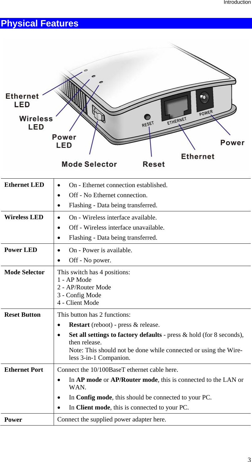
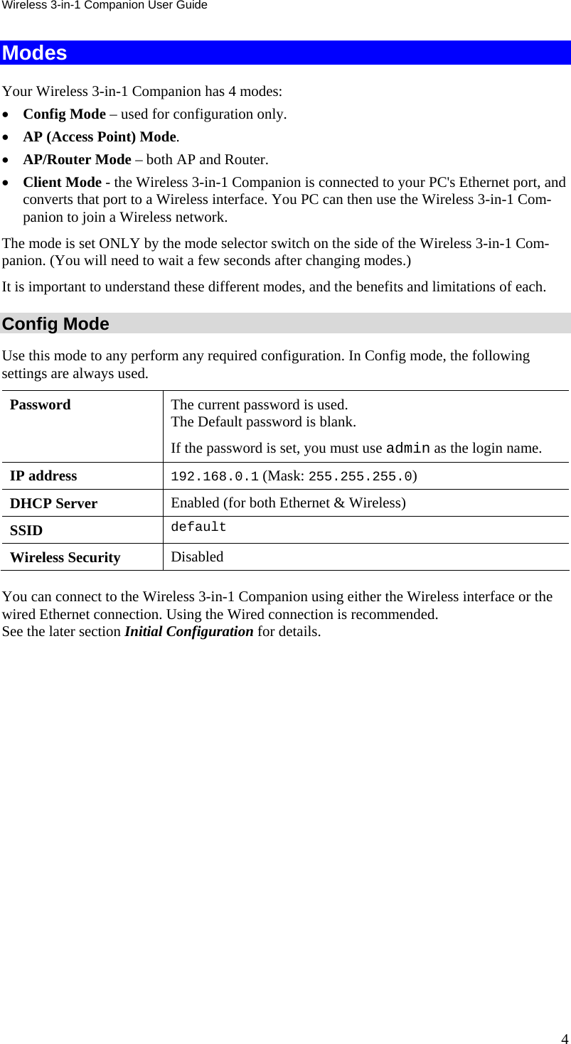
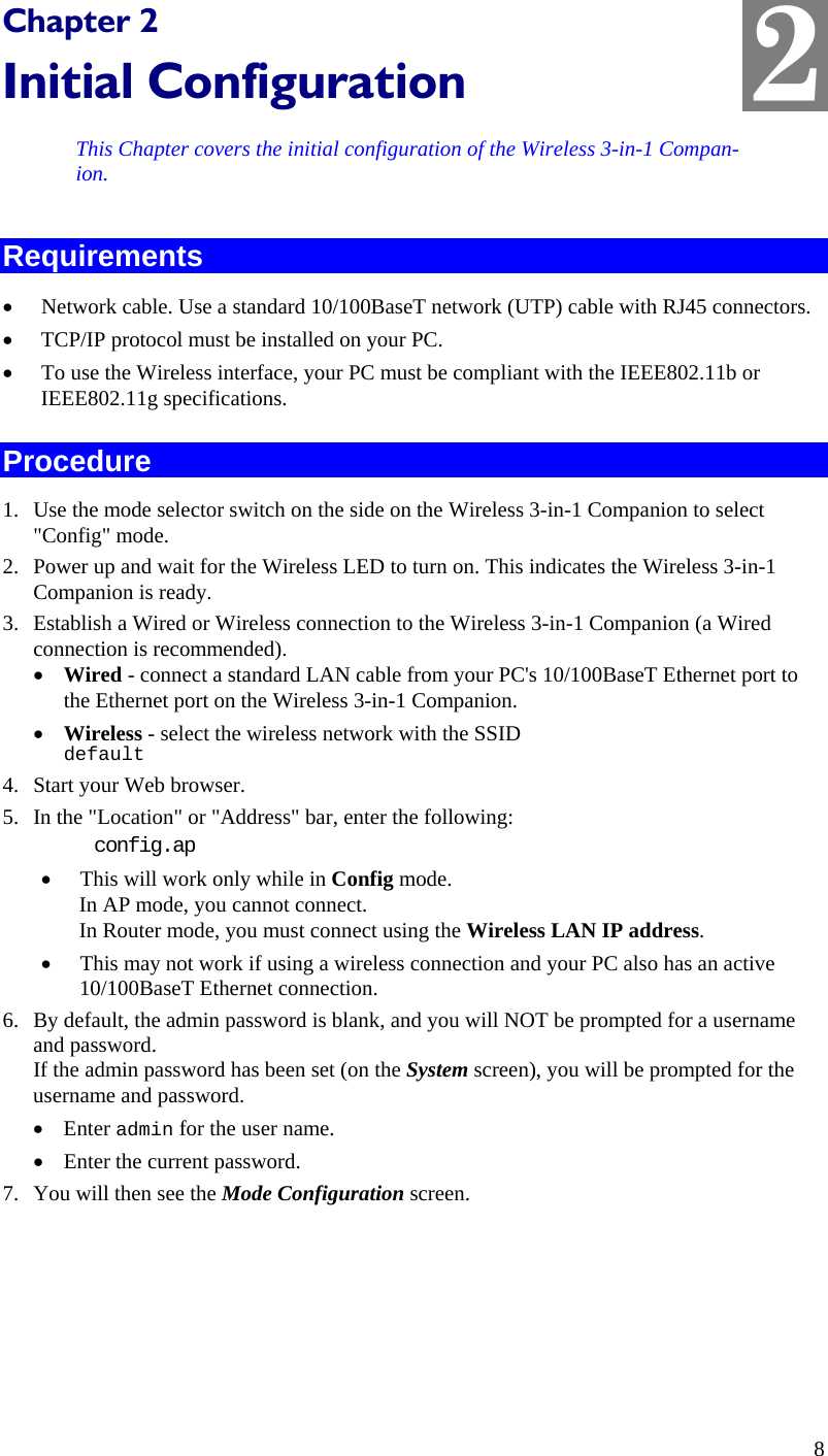
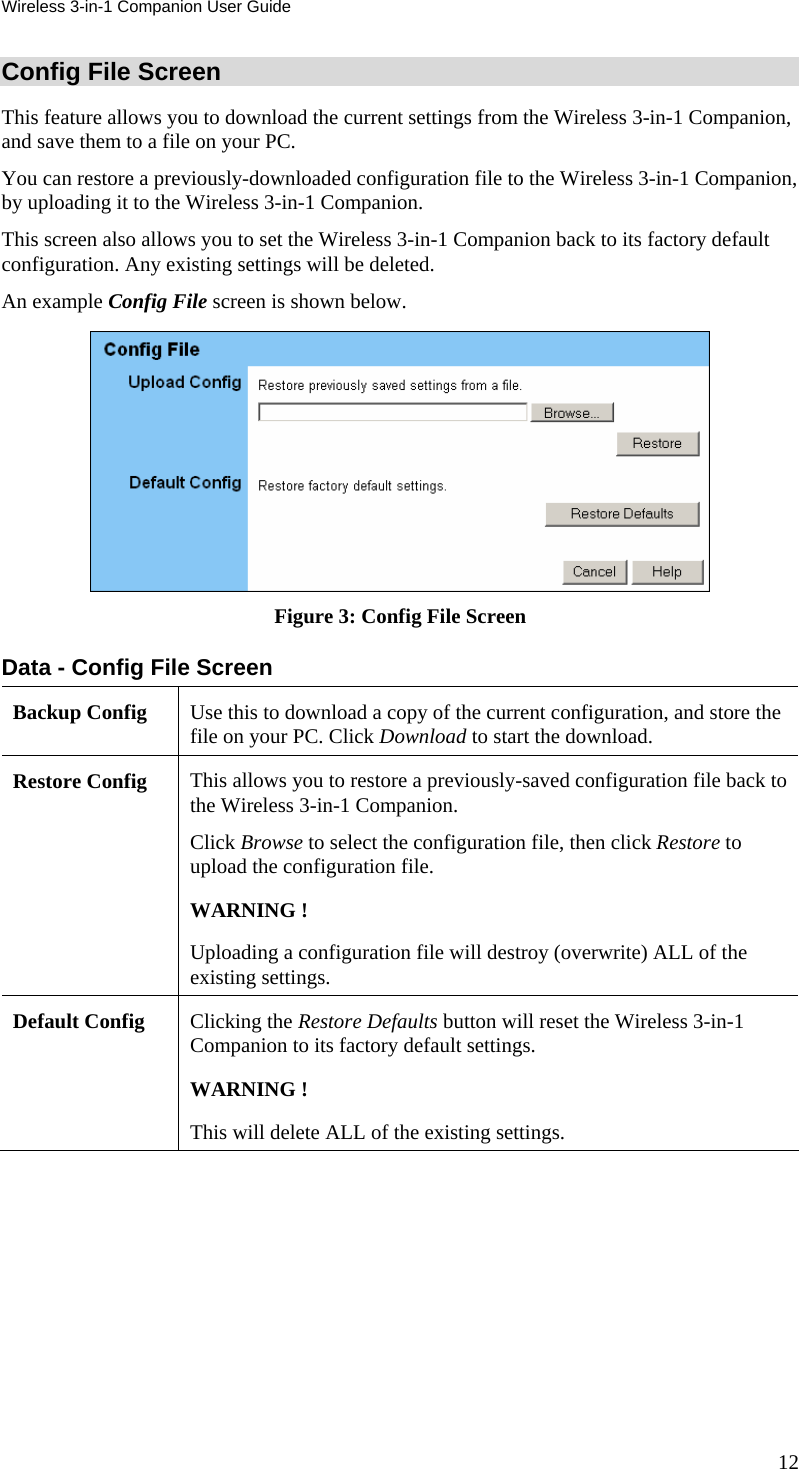
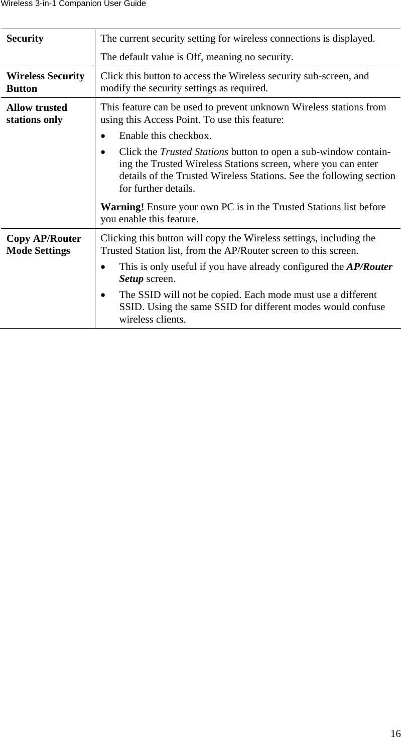
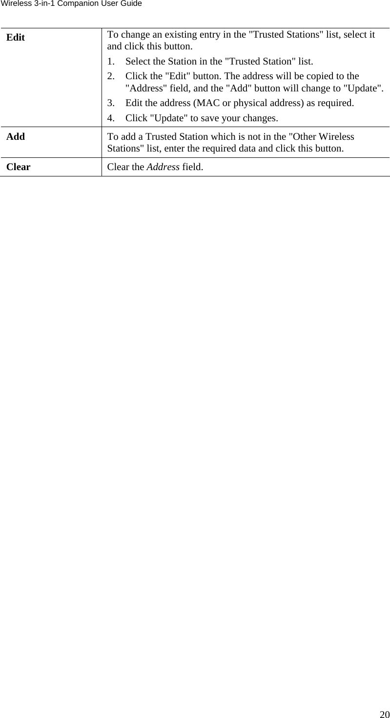
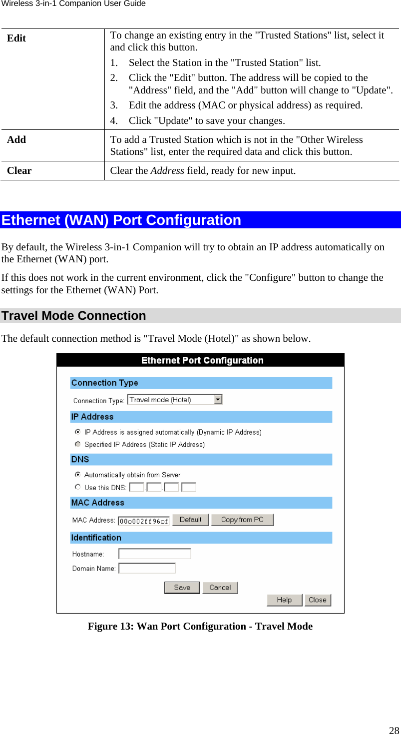

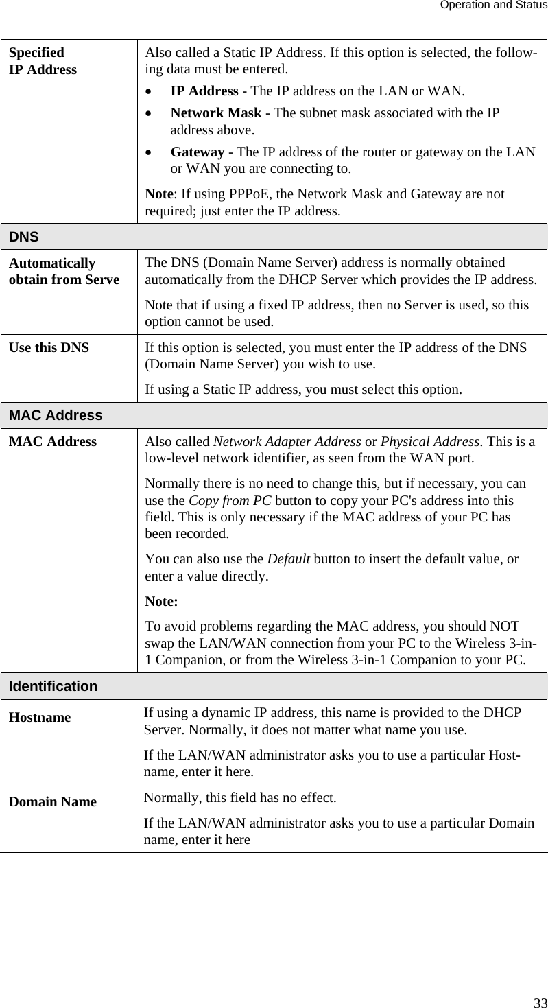
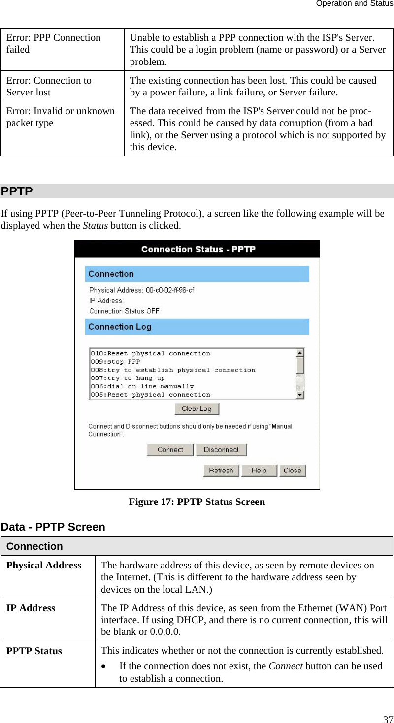
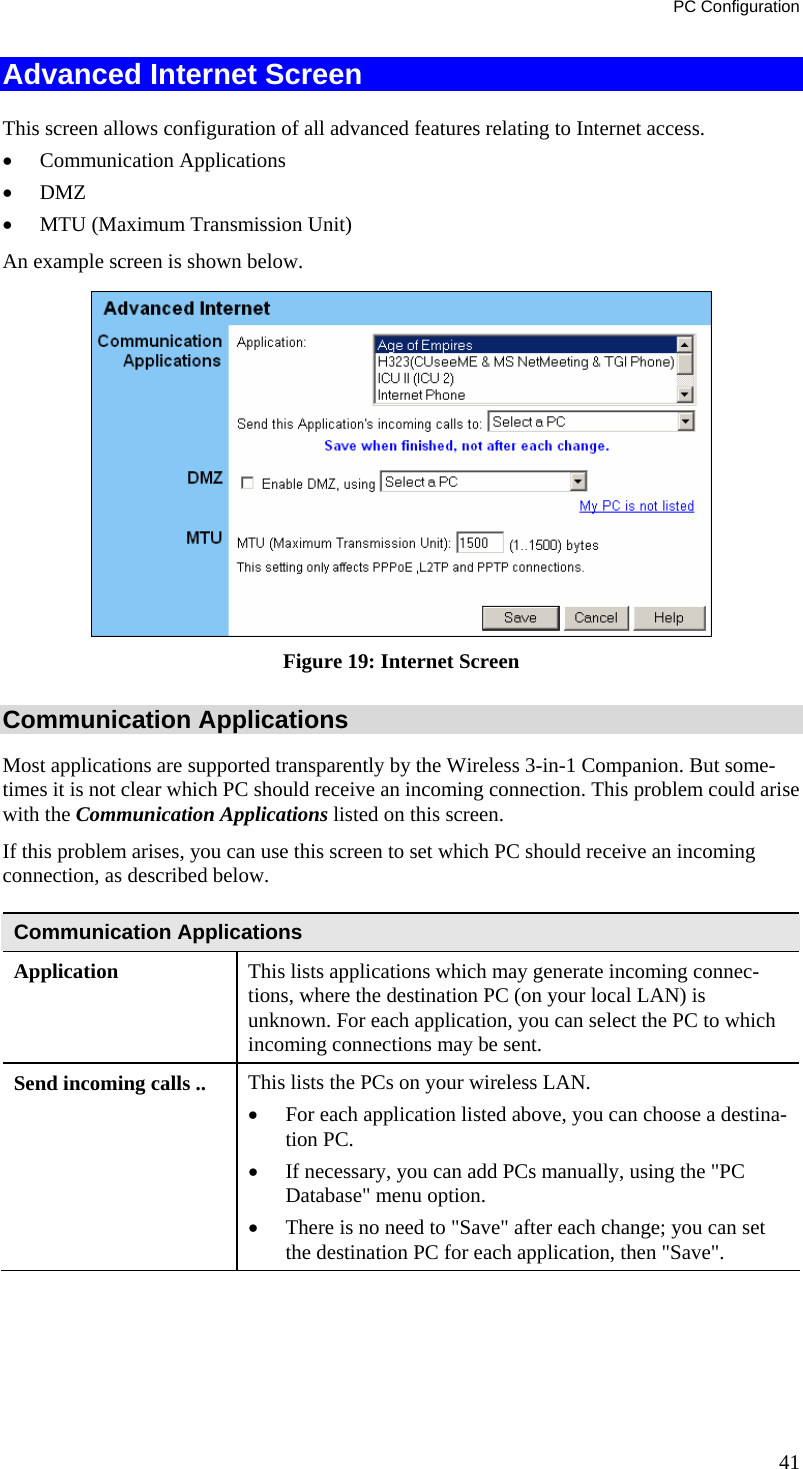

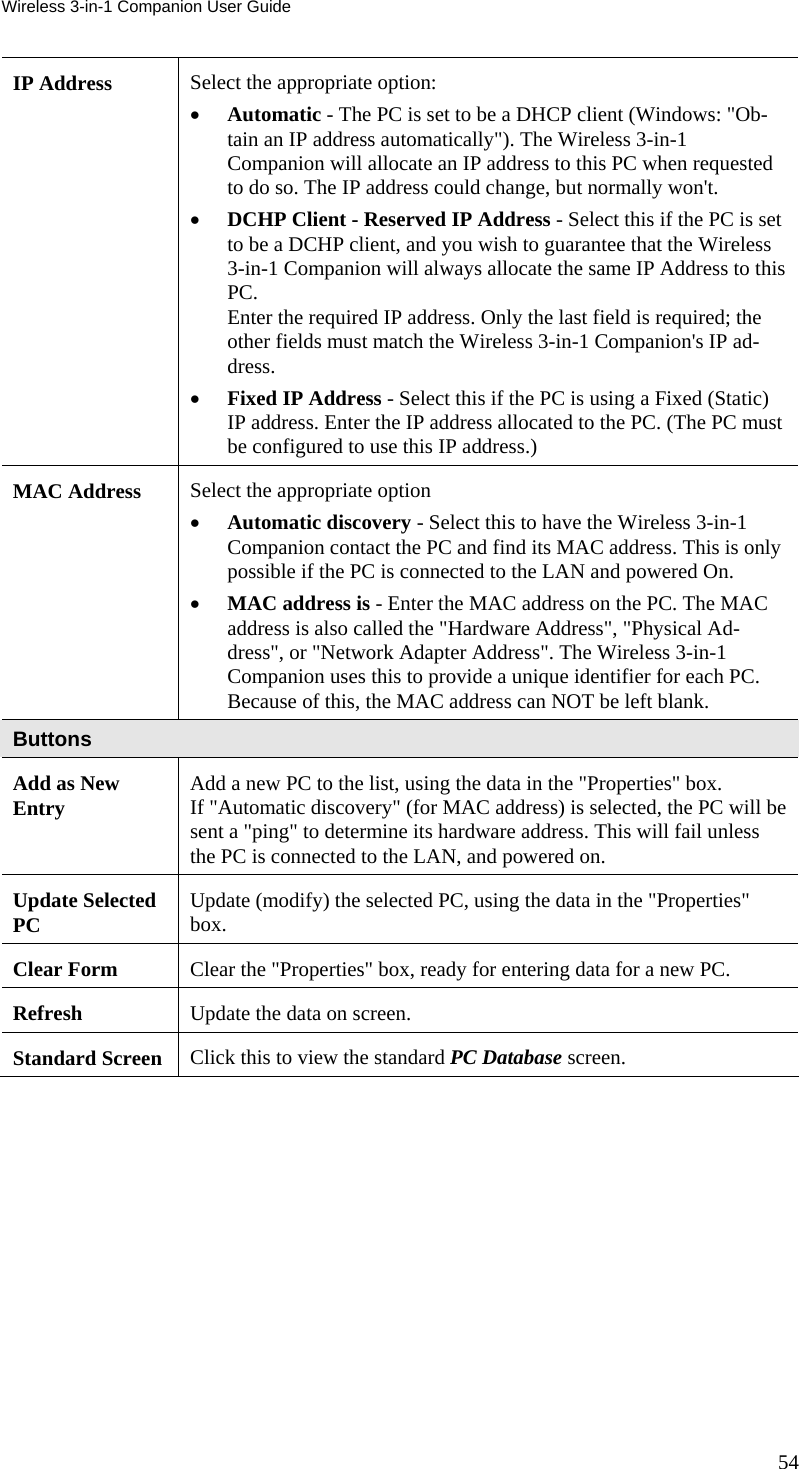
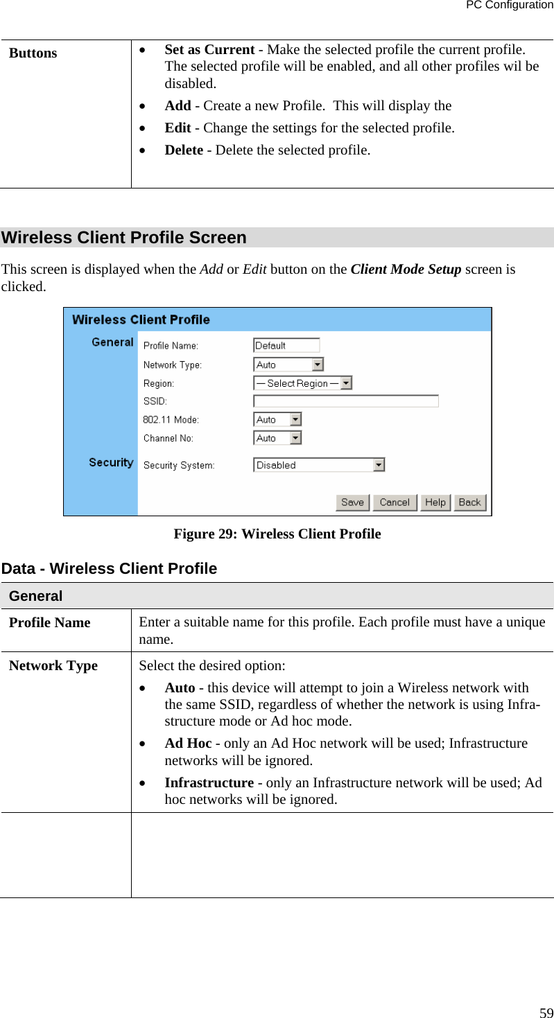
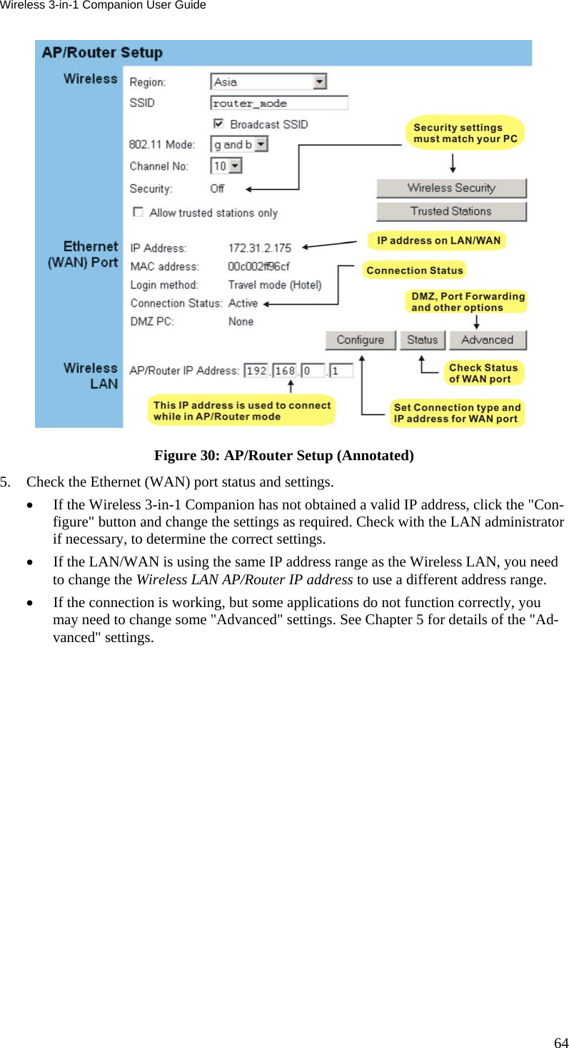
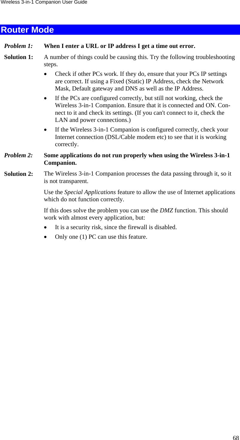
![Wireless 3-in-1 Companion User Guide Client Mode Setup The screen for Client Mode is reached by clicking the "Config" button for Client Mode on the Mode Configuration screen. In client mode, you can create a Profile for each Wireless network you use regularly. • A "Profile" contains all settings for the Wireless network, including the security settings. • Only one (1) Profile can be enabled at any time. • If the Wireless network defined by the currently-enabled profile is not available, then no wireless connection will be made. Client Mode Setup Screen Figure 28: Client Mode Setup Screen Data - Client Mode Setup Screen Wireless Profiles All available profiles are listed. For each profile, the following data is displayed: • * If a * is displayed before the name of the profile, this indicates the profile is the current profile (it is enabled). • Profile Name The current profile name is displayed. • [SSID] The current SSID associated with this profile. • Type The network type - Auto, Ad Hoc, or Infrastructure. • Security The current security system (e.g. WEP ) is displayed. 58](https://usermanual.wiki/Sercomm/IP802SMV2/User-Guide-534960-Page-62.png)