Sercomm NA403 Zigbee / WiFi Compact Monitoring Gateway User Manual Cardbus USB Wireless Adapter
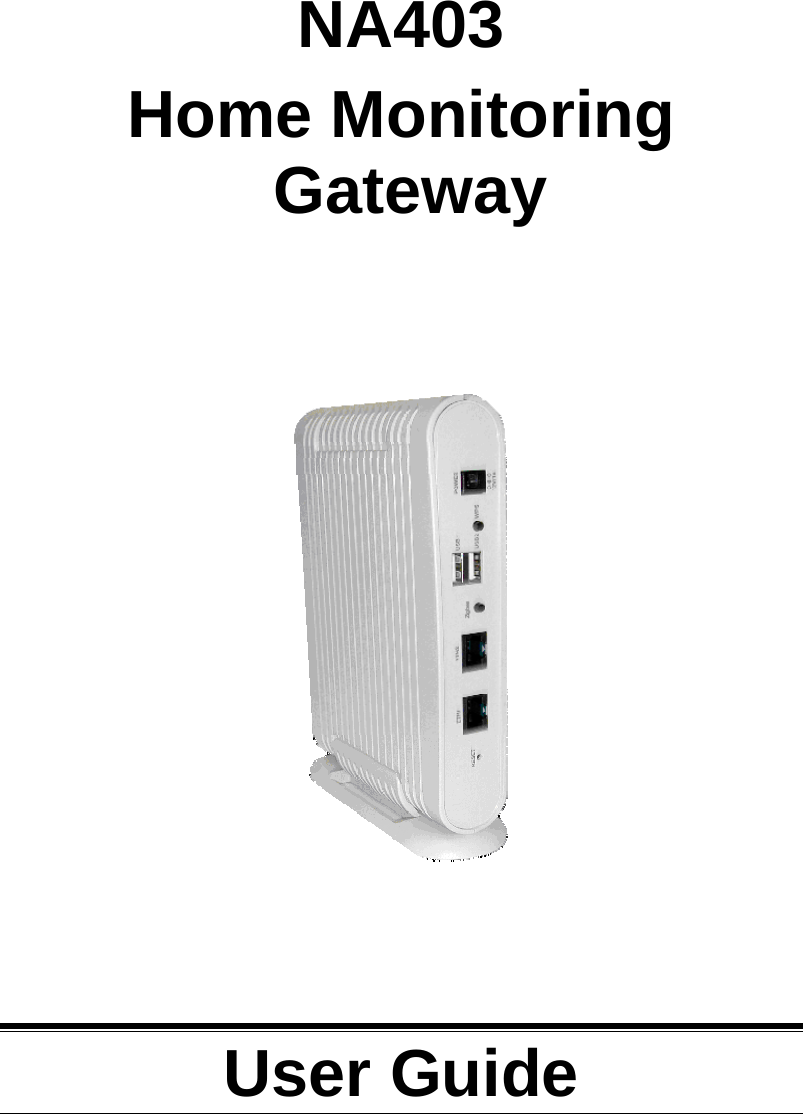
Sercomm Corporation Zigbee / WiFi Compact Monitoring Gateway Cardbus USB Wireless Adapter
UserManual.wiki
>
Sercomm
>
NA403 User Manual
Manual
Navigation menu
Upload a User Manual
Namespaces
Wiki Guide
HTML
PDF
Info
Views
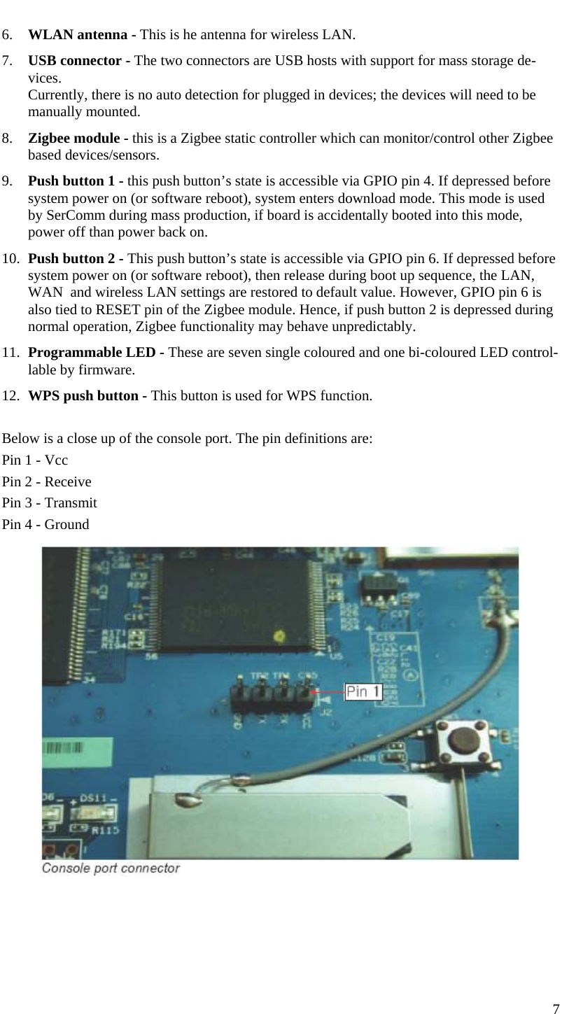
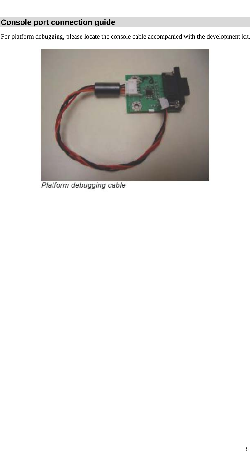
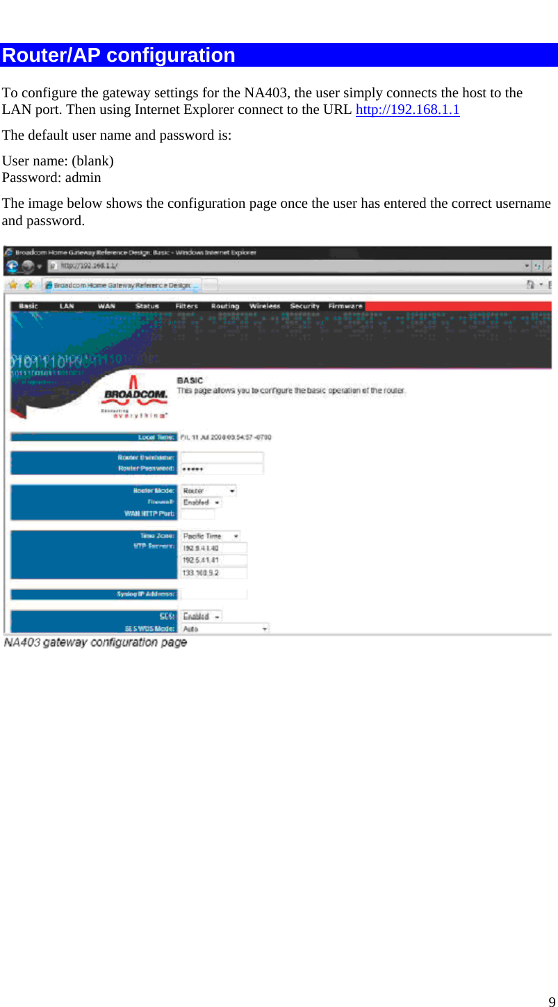
User Manual
Discussion / Help
Navigation