Sercomm NA502S Multiple RF Home Gateway User Manual Cardbus USB Wireless Adapter
Sercomm Corporation Multiple RF Home Gateway Cardbus USB Wireless Adapter
Sercomm >
Users Manual
i
NA502S
Multiple RF Home Gate-
way
User Guide

ii
Table of Contents
CHAPTER 1 INTRODUCTION .............................................................................................. 1
Package Contents .............................................................................................................. 1
Features .............................................................................................................................. 1
LEDs ................................................................................................................................... 2
CHAPTER 2 INITIAL INSTALLATION............................................................................... 5
Requirements ..................................................................................................................... 5
Procedure ........................................................................................................................... 5
SIM Card Installation ....................................................................................................... 7
CHAPTER 3 CONFIGURATION ........................................................................................... 8
Configuration ..................................................................................................................... 8
APPENDIX A SPECIFICATIONS .......................................................................................... 9
Multiple RF Home Gateway ............................................................................................. 9
Regulatory Approvals ....................................................................................................... 9
Copyright 2016. All Rights Reserved.
Document Version: 1.2
All trademarks and trade names are the properties of their respective owners.

1
Chapter 1
Introduction
This Chapter provides an overview of the Multiple RF Home Gateway's fea-
tures and capabilities.
Congratulations on the purchase of your new Multiple RF Home Gateway. The Multiple RF
Home Gateway is a consumer electronic device, which is designed to bridge all appliances of
your home, from IP cameras to sensors, and allow you to monitor and manage them over the
Internet. Most of the devices can be paired with the gateway via a single button push.
Package Contents
The following items should be included:
Multiple RF Home Gateway Unit x 1
Power Adapter x 1
If any of the above items are damaged or missing, please contact your dealer immediately.
Features
MT7621S processor with128MB Flash and 512MB RAM
One 10/100/1000 Ethernet port with RJ45 connector
Front Panel LEDs
Z-Wave Transceiver
ZigBee Transceiver
Bluetooth Transceiver
3G Wireless
USB 2.0 port
Battery Backup (2~4 hours)
SIM Card Slot
Built-in Siren
Two-way Voice
Internal antenna for WiFi, ZigBee, Z-Wave, Bluetooth, 433/345 and 3G
1
2
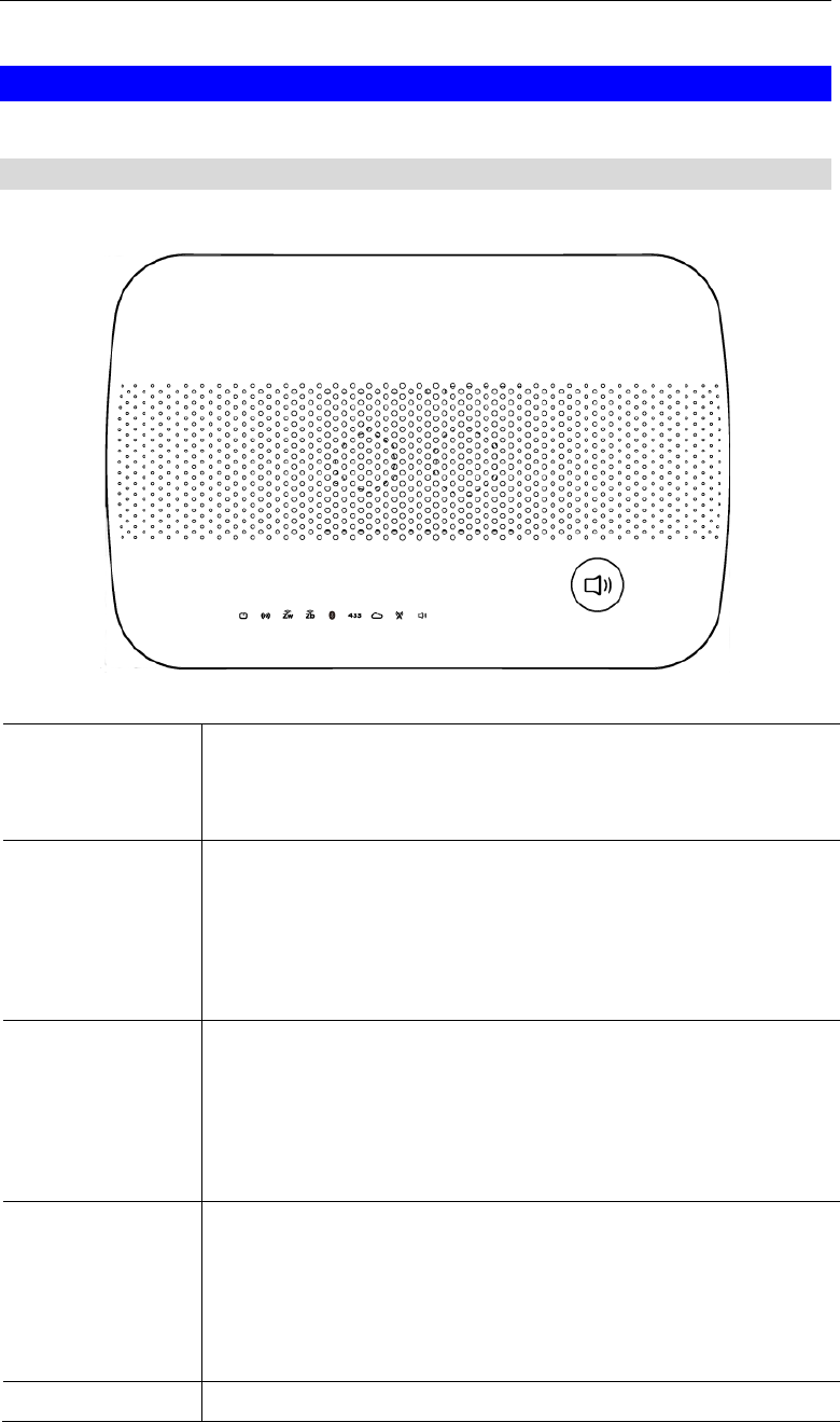
LEDs
Front Panel
The Multiple RF Home Gateway has 9 LEDs.
POWER (Green)
On - Power On/Normal Operation
Off - Power Off
Flashing - Rebooting.
WiFi
(Green)
On - WPS mode is selected.
On (5 seconds) - WiFi connection is established.
Off - No WiFi connection available.
Flashing - Data is being transmitted or received via the Wireless
connection.
Z-Wave
(Green)
On - Z-Wave mode is selected.
On (5 seconds) - Z-Wave sensor added or synchronization is
successful.
Off - Z-Wave module is in idle mode.
Flashing - Z-Wave module is in active mode.
ZigBee
(Green)
On - ZigBee mode is selected.
On (5 seconds) - ZigBee sensor added or synchronization is
successful.
Off - ZigBee module is in idle mode.
Flashing - ZigBee module is in active mode.
Bluetooth LE
On - Bluetooth mode is selected.
3
(Green)
On (5 seconds) - Bluetooth sensor added or synchronization is
successful.
Off - Bluetooth module is in idle mode.
Flashing - Bluetooth module is in active mode.
3G
(Green)
On - 3G connection established.
Off - No active 3G connection.
Flashing - Data is being transmitted or received via the 3G con-
nection.
433MHz/345MHz
(Green)
On - 433MHz/345MHz mode is selected.
On (5 seconds) - 433MHz/345MHz sensor added or synchroniza-
tion is successful.
Off - 433MHz/345MHz module is in idle mode.
Flashing - 433MHz/345MHz module is in active mode.
Service
(Green)
On - Cloud service is available and working properly.
Off - Cloud service is not available.
Flashing - Cloud service is not sending data properly.
Voice
(Green)
On - Voice function is enabled.
Off - Voice function is disabled.
Flashing - A voice call is proceeding.
Voice Button
Push the Voice button on the device to start the voice call.
Push the Voice button for three seconds again to stop the voice
call.
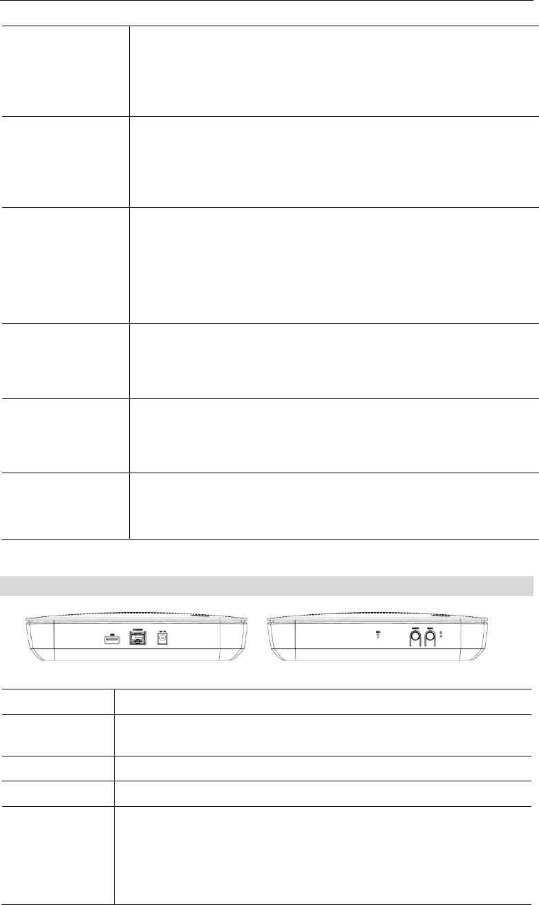
Rear/Side Panel
Power Port
Connect the supplied power adapter here.
ETHERNET
Port
Use a standard LAN cable (RJ45 connector) to connect your PC to the
port.
USB Port
The connector is USB host with support for mass storage device.
Mic
The built-in microphone is located on the side of the device.
Select Button
Push the Select button on the device to choose the desired RF mode
(WiFi/Z-Wave/ZigBee/Bluetooth LE/433MHz), and then the LED
of the selected mode will be on.
Push the Select button for three seconds again to unselect the RF
mode if needed.

4
Sync Button
After selecting the RF mode, push the Sync button to synchronize
the gateway and sensors.
Push the Sync button for three seconds again to stop the synchroni-
zation process if needed.
Reset
This button has two (2) functions:
Reboot. When pressed and released, the Multiple RF Home
Gateway will reboot (restart).
Clear All Data. This button can also be used to clear ALL data
and restore ALL settings to the factory default values.
To Clear All Date and restore the factory default values:
1. Power On.
2. Keep holding the Reset Button down for 3 seconds.
Release the Reset Button. The Multiple RF Home Gateway is now using
the factory default values.
5
Chapter 2
Initial Installation
This Chapter covers the software installation of the Multiple RF Home Gate-
way.
Requirements
Use a standard 10/100/1000 BaseT network (UTP) cable with RJ45 connector.
Procedure
1. Choose an Installation Site
Select a suitable place to install the Multiple RF Home Gateway.
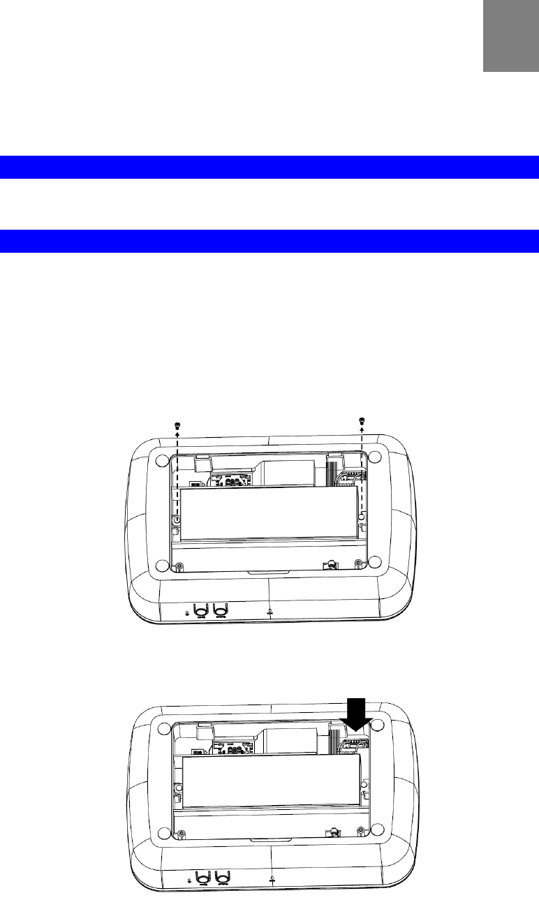
2. Connect Battery Plug Connector
The supplied backup battery can provide excellent continuous power source when discon-
necting power to the device.
1. Remove the screws on the back cover of the device with a screwdriver.
2. Put the battery connector into the plug, and this will charge and maintain your device’s
backup battery.
2
6
3. Attach the back cover to the device with the screws.
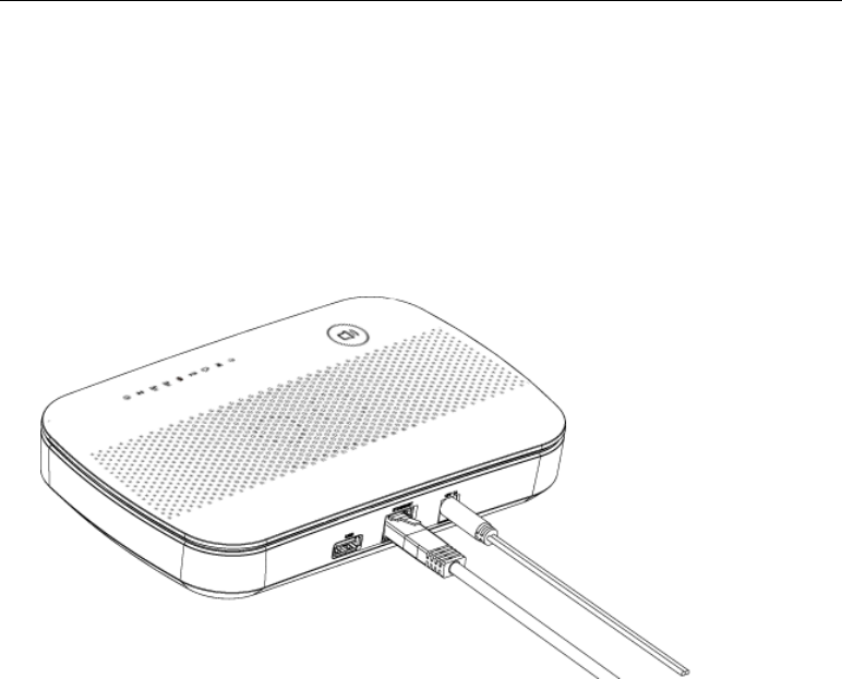
3. Connect LAN Cable
Use a standard LAN cable to connect the device to the Ethernet port on the Multiple RF
Home Gateway.
4. Power Up
Connect the supplied power adapter to the Multiple RF Home Gateway. Use only the pow-
er adapter provided. Using a different one may cause hardware damage.
5. Check the LEDs
The Power LED should be ON.
The WiFi LED should be ON (provided the PC is also ON.)
Initial Installation
7
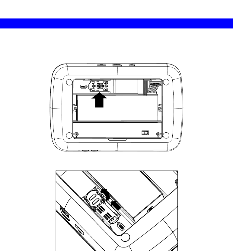
SIM Card Installation
1. Ensured the device is powered off.
2. Remove the screws on the back cover of the device with a screwdriver.
3. Find the location of the SIM card tray.
4. Push the SIM card cover upward.
5. Insert the SIM card into the slot. Make sure the SIM card is installed correctly.
6. Put the SIM card cover back.
7. Attach the back cover to the device with the screws.

8
Chapter 3
Configuration
This Chapter provides Setup details of the Gateway.
Configuration
The Multiple RF Home Gateway can offer customers with seamless communication between
devices and clouds while at home or away. This gateway is designed to provide complete
connectivity with all certified devices including cameras, security systems and WiFi/ZigBee/Z-
Wave/Bluetooth/3G devices.
Preparation
Before attempting to configure the Multiple RF Home Gateway, please ensure that:
Your PC can establish a physical connection to the Multiple RF Home Gateway. The PC
and the Multiple RF Home Gateway must be directly connected (using the Hub port on the
Multiple RF Home Gateway) or on the same LAN segment.
The Multiple RF Home Gateway must be installed and powered ON.
Choose the desired RF mode by using the Select button of the gateway, and then push the
Sync button for pairing the gateway and sensors. Make sure that the gateway and added
sensors are synchronized successfully before using.
After completing the preparation, the Multiple RF Home Gateway is ready to be used.
3
9
Appendix A
Specifications
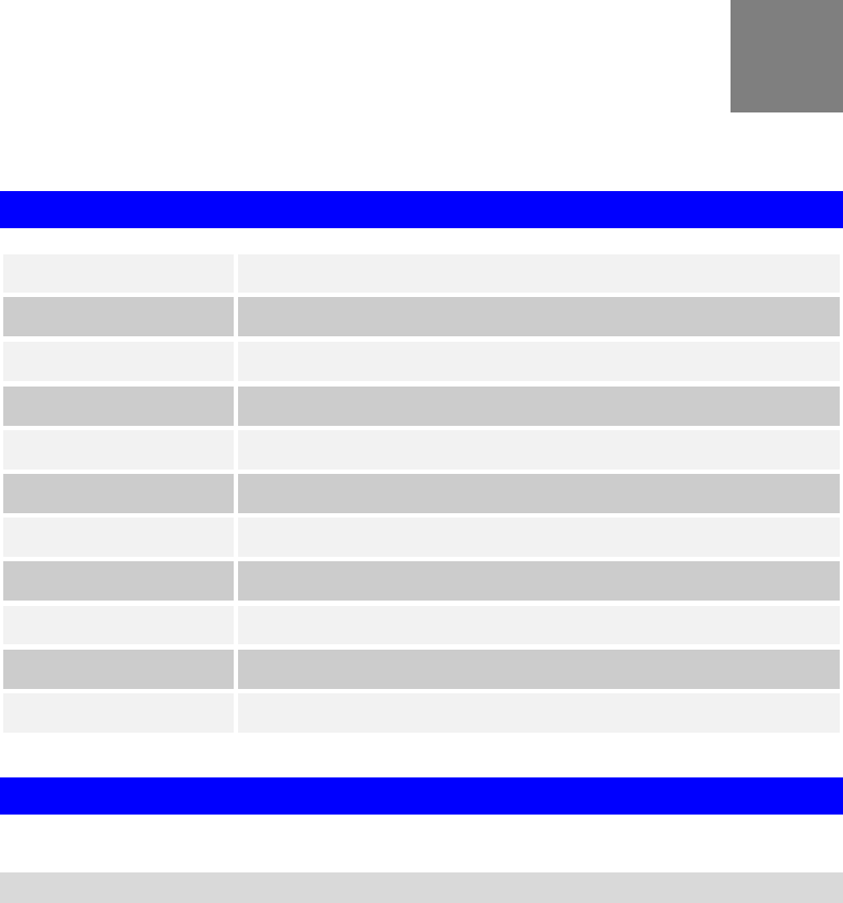
Multiple RF Home Gateway
Model
Multiple RF Home Gateway
Dimensions
222mm(W) * 148mm(D) * 48mm(H)
Operating Temperature
0 C to 40 C
Buttons
4
Network Protocol:
TCP/IP
Network Interface:
1 * 10/100/1000BaseT (RJ45) LAN connection
LEDs
9
Battery
2S1P 18650 Battery
USB Port
1 * USB 2.0 Type A Port
SIM Card Slot
1
Power Adapter
12V, 2A
Regulatory Approvals
FCC Statement
Federal Communication Commission Interference Statement
This equipment has been tested and found to comply with the limits for a Class B digital device,
pursuant to Part 15 of the FCC Rules. These limits are designed to provide reasonable protec-
tion against harmful interference in a residential installation. This equipment generates, uses
and can radiate radio frequency energy and, if not installed and used in accordance with the
instructions, may cause harmful interference to radio communications. However, there is no
guarantee that interference will not occur in a particular installation. If this equipment does
cause harmful interference to radio or television reception, which can be determined by turning
the equipment off and on, the user is encouraged to try to correct the interference by one of the
following measures:
- Reorient or relocate the receiving antenna.
- Increase the separation between the equipment and receiver.
A

10
- Connect the equipment into an outlet on a circuit different from that
to which the receiver is connected.
- Consult the dealer or an experienced radio/TV technician for help.
FCC Caution: Any changes or modifications not expressly approved by the party responsible
for compliance could void the user's authority to operate this equipment.
This device complies with Part 15 of the FCC Rules. Operation is subject to the following two
conditions: (1) This device may not cause harmful interference, and (2) this device must accept
any interference received, including interference that may cause undesired operation.
IMPORTANT NOTE:
Radiation Exposure Statement:
This equipment complies with FCC radiation exposure limits set forth for an uncontrolled
environment. This equipment should be installed and operated with minimum distance 20cm
between the radiator & your body.
This transmitter must not be co-located or operating in conjunction with any other antenna or
transmitter.
Country Code selection feature to be disabled for products marketed to the US/CANADA
Operation of this device is restricted to indoor use only