Sercomm NA900ZB ZigBee Home Monitoring Gateway User Manual
Sercomm Corporation ZigBee Home Monitoring Gateway
Sercomm >
User manual
ZigBee Home Monitoring
Gateway
User Guide

i
Table of Contents
CHAPTER 1 INTRODUCTION .............................................................................................1
Package Contents ..............................................................................................................1
Specification.......................................................................................................................1
LEDs...................................................................................................................................2
CHAPTER 2 INITIAL INSTALLATION..............................................................................5
Requirements.....................................................................................................................5
Procedure...........................................................................................................................5
CHAPTER 3 BOARD DESCRIPTION..................................................................................6
Components and connectors ............................................................................................6
CHAPTER 4 ............................................................................................................................10
FCC STATEMENT ................................................................................................................10
FCC STATEMENT.........................................................................................................10
Copyright © 2012. All Rights Reserved.
Document Version: 1.0
All trademarks and trade names are the properties of their respective owners.

1
Chapter 1
Introduction
This Chapter provides an overview of the ZigBee Home Monitoring Gate-
way's features and capabilities.
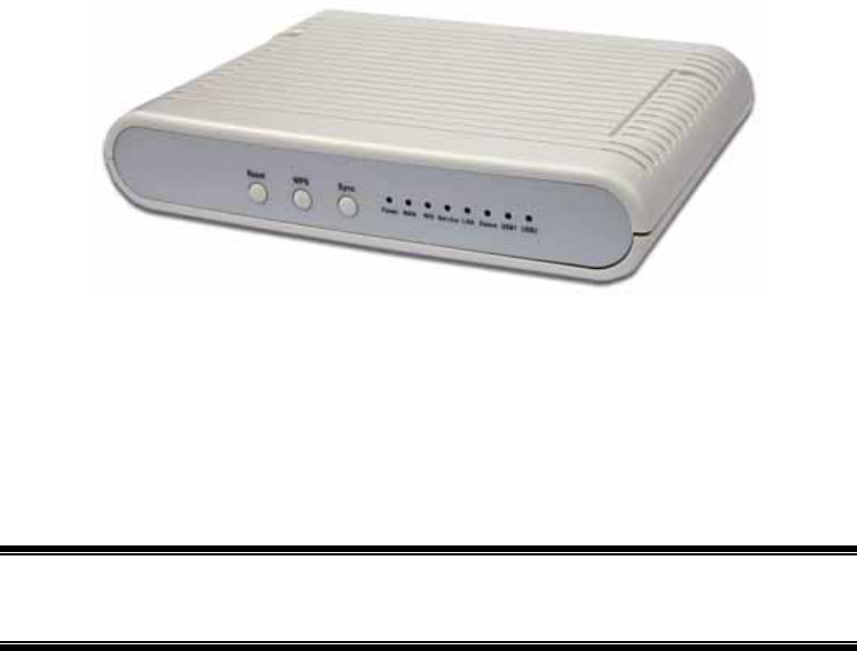
Congratulations on the purchase of your new ZigBee Home Monitoring Gateway. The ZigBee
Home Monitoring Gateway is a consumer electronic device, which is used for home monitor-
ing and security.
Package Contents
The following items should be included:
• The ZigBee Home Monitoring Gateway Unit
• Power Adapter
If any of the above items are damaged or missing, please contact your dealer immediately.
Specification
• DDR2 SDRAM 64MB
• NAND 32MB Flash
• Four Ethernet ports with RJ45 connectors.
• Front Panel LEDs
• Zigbee module
• Two USB 2.0 ports
• Sync button
• WPS button
• Reset button
• Power In connector
• Two Internal antennae
1
2
LEDs
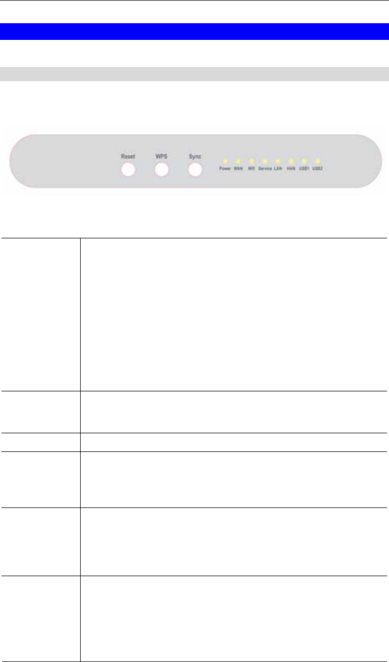
Front-mounted LEDs
The ZigBee Home Monitoring Gateway has 8 LEDs.
Reset This button has two (2) functions:
• Reboot. When pressed and released, the ZigBee Home Monitoring
Gateway will reboot (restart).
• Clear All Data. This button can also be used to clear ALL data and
restore ALL settings to the factory default values.
To Clear All Data and restore the factory default values:
1. Power On.
2. Keep holding the Reset Button down for 8 seconds.
Release the Reset Button. The ZigBee Home Monitoring Gateway is
now using the factory default values.
WPS button Push the WPS button on the device and on your other wireless device to
perform WPS function that easily creates an encryption-secured wireless
connection automatically.
Sync Button Push this button to synchronize for portal server or ZigBee clients.
POWER
(Green)
• On - Power On
• Off - Power Off
• Flashing - Reboot or Firmware upgrade.
WAN (Green) • On - Connection to the Gateway attached to the WAN (Internet)
port is established.
• Off - No connection to the Gateway.
• Flashing - Data is being transmitted or received via the connection.
WiFi & WPS WiFi
• On (Green) - Wireless connection available
• Off (Green) - No Wireless connection available.
• Flashing (Green) - Data is being transmitted or received via the
Wireless connection.

3
WPS
• On (Amber) - Problem occurred while trying to enable the
WPS function.
• On (Green) - WPS function is enabled.
• Flashing - Data is being transmitted or received via the connection.
Service • On (Green)- Open for Sensor Binding (Add)
• Off - System is in ready mode, no sensor is needed to be bined
(added.)
• Flashing - Sensor is binding (adding)
LAN (Green) • On (Green)- LAN connection established.
• Off - No active connection on the corresponding LAN port.
• Flashing - Data is being transmitted or received via the correspond-
ing LAN (hub) port.
HAN • On - Zwave//ZigBee function enabled.
• Off - Zwave/ZigBee function disabled
• Flashing - Data is being transmitted or received via the connection.
USB (1~2) • On (Green)- USB connection established.
• Off - No active connection on the corresponding USB port.
• Flashing - Data is being transmitted or received via the correspond-
ing USB port.
4
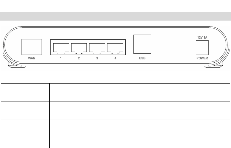
Rear Panel
WAN port
(10/100BaseT) Connect the DSL or Cable Modem here. If your modem came with a
cable, use the supplied cable. Otherwise, use a standard LAN cable.
LAN (1~4) Port Use standard LAN cables (RJ45 connectors) to connect your PCs to
these ports.
USB (1~2) Port The two connectors are USB hosts with support for mass storage
devices.
Power Port Connect the supplied power adapter here.
5
Chapter 2
Initial Installation
This Chapter covers the software installation of the ZigBee Home Monitoring
Gateway.
Requirements
• Network cables. Use standard 10/100BaseT network (UTP) cables with RJ45 connectors.
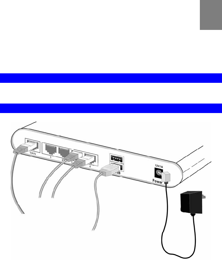
Procedure
1. Choose an Installation Site
Select a suitable place to install the ZigBee Home Monitoring Gateway.
2. Connect LAN Cables
Use standard LAN cables to connect devices to the Ethernet ports on the ZigBee Home
Monitoring Gateway.
4. Power Up
Connect the supplied power adapter to the ZigBee Home Monitoring Gateway. Use only
the power adapter provided. Using a different one may cause hardware damage.
5. Check the LEDs
• The POWER LED should be ON.
• The LAN LED should be ON (provided the PC is also ON.)
2
6
Chapter 3
Board Description
This Chapter provides board description for the ZigBee Home Monitoring
Gateway.
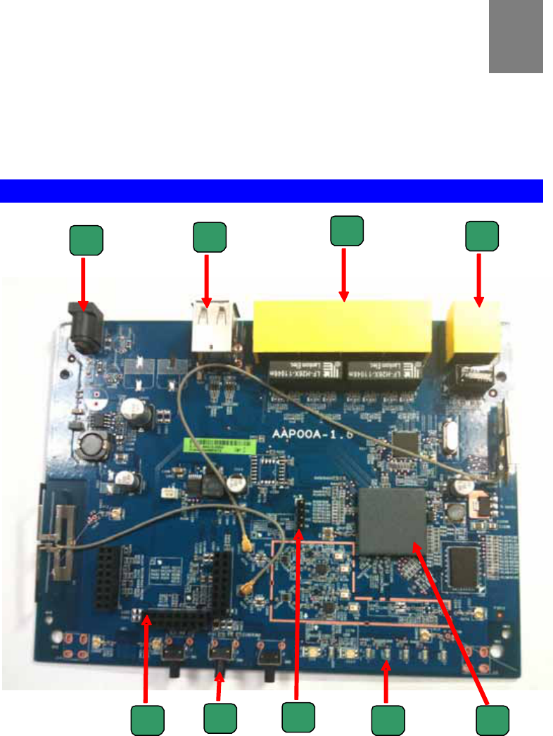
Components and connectors
|
3
9 1
4
23
57
68

7
• 1. USB type A connector
• 2. LAN port
• 3. WAN port
• 4. Expansion slot connectors
• 5. Push buttons.
• 6. Console port
• 7. LEDs
• 8. RT3662 processor
• 9. DC power jack
8
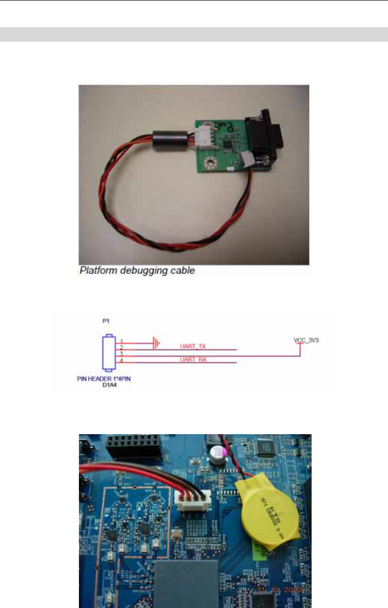
Console port connection guide
For platform debugging, please locate the console cable accompanied with the development kit.
Then follow the steps illustrated below:
Pin definition
1. Connect cable to console port
2. Execute minicom on Linux host machine
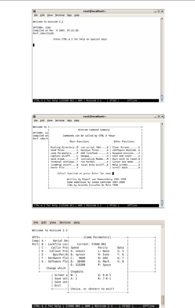
9
3. Press Ctrl+A then Z to enter minicom configuration
4. Set Comm port to baud rate 57600, 8 data bits, no parity bits, and one stop bit.

10
Chapter 4
FCC STATEMENT 4
This equipment has been tested and found to comply with the limits for a Class B
digital device, pursuant to part 15 of the FCC rules. These limits are designed to
provide reasonable protection against harmful interference in a residential installation.
This equipment generates, uses and can radiate radio frequency energy and, if not
installed and used in accordance with the instructions, may cause harmful interference
to radio communications. However, there is no guarantee that interference will not
occur in a particular installation. If this equipment does cause harmful interference to
radio or television reception, which can be determined by turning the equipment off
and on, the user is encouraged to try to correct the interference by one or more of the
following measures:
-Reorient or relocate the receiving antenna.
-Increase the separation between the equipment and receiver.
-Connect the equipment into an outlet on a circuit different from that to which the
receiver is connected.
-Consult the dealer or an experienced radio/TV technician for help.
You are cautioned that changes or modifications not expressly approved by the party
responsible for compliance could void your authority to operate the equipment.
FCC RF Radiation Exposure Statement:
1. This Transmitter must not be co-located or operating in conjunction with any other
antenna or transmitter.
2. This equipment complies with FCC RF radiation exposure limits set forth for an
uncontrolled environment. This equipmentshould be installed and operated with a
minimum distance of 20 centimeters between the radiator and your body.