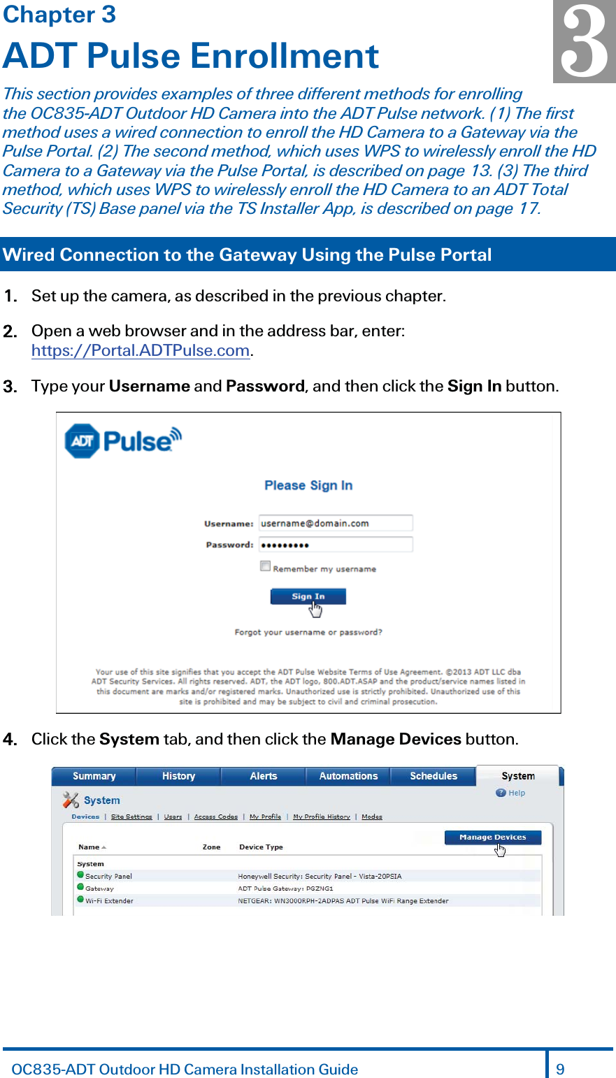
Sercomm OC835 Waterproof HD IP Camera User Manual OC835 ADT Waterproof Wireless Day Night HD Camera

Sercomm Corporation Waterproof HD IP Camera OC835 ADT Waterproof Wireless Day Night HD Camera

User Manual

ADT Pulse® Interactive Solutions OC835-ADT  Quick Installation Guide
Table of Contents CHAPTER 1 INTRODUCTION ............................................................................ 3 Overview ...............................................................................................................  3 Physical Details ................................................................................................... 4 Package Contents ............................................................................................... 6 CHAPTER 2 BASIC SETUP ................................................................................. 7 Installation ............................................................................................................  7 CHAPTER 3 ADT PULSE ENROLLMENT ......................................................... 9 Wired Connection to the Gateway Using the Pulse Portal......................... 9 Wireless Connection to the Gateway Using the Pulse Portal .................. 13 Wireless Connection to the TS Base Using the Installer App .................. 17 If the Camera Continually Goes Offline ........................................................ 20 CHAPTER 4 WALL MOUNTING ...................................................................... 21 APPENDIX A SPECIFICATIONS ...................................................................... 23 OC835-ADT Outdoor Day/Night HD Camera ............................................ 23 Regulatory Approvals ...................................................................................... 24 Property of ADT LLC.  Information accurate as of published date and is provided “as is” without warranty of any kind.  ©2015 ADT LLC dba ADT Security Services. All rights reserved. ADT, the ADT logo, 800 ADT.ASAP and the product/service names listed are marks and/or registered marks of ADT. Unauthorized use is strictly prohibited. Third party marks are property of their respective owners. OC835-ADT-QIG-00 (08/15) 2  OC835-ADT Outdoor HD Camera Installation Guide
Chapter 1 Introduction This section provides information about the OC835-ADT Outdoor Day/Night HD Camera's features, components and capabilities. Overview The OC835-ADT is a true outdoor day/night wireless camera with HD resolution, 802.11n Wi-Fi connectivity and Wi-Fi Protected Setup (WPS) support. This camera is intended for use with ADT Pulse®. Features x Standalone Design.  The camera is a standalone system with built-in CPU and video encoder. It requires only a power source and a connection to the ADT Pulse Gateway or ADT Total Security (TS) Base panel. x Dual Video Support.  The OC835-ADT supports H.264 and MJEPG video compression. x Day/Night Switch:  With the day/night switching feature, you can view and record images even at night. x IR LED Support. The infrared LED can provide illumination for up to 6 meters, providing superior video quality under low-light conditions such as on cloudy days, or in the early morning or evening.  x PIR (Passive Infrared Sensor) Support. The embedded PIR Sensor senses infrared light radiating from human bodies in its field of view. x Built-in Heater.  The built-in heater ensures that the camera will continue to operate even in extremely cold outdoor climates. The heater turns on when the temperature falls below 42qF (6qC). Wireless Features  x Supports 802.11n Wireless Standard. The 802.11n standard provides backward compatibility with the 802.11b and g standards. x Supports WPS. Wi-Fi Protected Setup (WPS) can simplify the process of connecting the Wireless HD Camera to the wireless network by using the push button configuration. x Wired and Wireless Network. The OC835-ADT can be connected to the Pulse network wirelessly. It can also be hardwired to the network. 1 OC835-ADT Outdoor HD Camera Installation Guide 3
Chapter 1 Introduction Physical Details Front  Figure 1: Front Panel Light Sensor  This is a hardware sensor to detect lux. Lens  The lens cannot be adjusted. Please ensure that the lens cover remains clean.  PIR Sensor  This is a Passive Infrared sensor to detect motion. Rear  Figure 2: Rear Panel Light Sensor Lens PIR SensorNetwork Port WPS/Reset Button DC Power Input Power LED Network/Wireless LED 4  OC835-ADT Outdoor HD Camera Installation Guide
Chapter 1 Introduction  DC Power Input  Connect the supplied 12V power adapter here. Do not use other power adapters; doing so may damage the camera. Power LED (Green, Amber) On (Green).  Power on. Off.  No power. Blinking (Green).  The Power LED blinks during start up for approximately 1 minute.  Blinking (Amber).  The firmware is being upgraded. On (Amber).  The firmware upgrade has failed. Network/Wireless LED (Green, Amber) On (Green).  Network connection is available (wired or wireless). Off.  Wired/wireless network is not connected or camera is not sending/receiving data. Blinking (Green).  Data is being transmitted or received via the wired/wireless connection. On (Amber).  If the LED is on for 5 seconds and then turns off, the WPS function has failed. Blinking (Amber).  The WPS connection is active. WPS/Reset Button   This button serves two functions on the camera. x WPS Pin Code Mode.  When pressed and held for 5 seconds during the Pulse enrollment process, the camera creates an encryption-secured wireless connection. x Reset. When pressed and held over 15 seconds, the camera reboots and the settings are restored to default values. Network Port  Use a Micro USB to RJ-45 Adapter Cable (not included) and a standard Ethernet cable (not included) to connect the camera to the Pulse Gateway or TS Base panel. Note: x Plugging in the Micro USB to RJ-45 Adapter Cable will disable the wireless interface. Only one interface can be active at any time. x The Micro USB to RJ-45 Adapter Cable should only be connected or disconnected when the camera is powered OFF. Attaching or detaching the Micro USB to RJ-45 Adapter Cable while the camera is powered on does NOT switch the interface between wired and wireless.  OC835-ADT Outdoor Day/Night HD Camera Installation Guide 5
Chapter 1 Introduction  Package Contents The following items are included in the package.   Figure 3: What’s in the Box 6  OC835-ADT Outdoor HD Camera Installation Guide
Chapter 2 Basic Setup This section provides information on how to assemble and configure the OC835-ADT Outdoor HD Camera. Installation  1.  Assemble the Camera Attach the Camera Stand to the camera.2. Make the Connection Using a Wired Connection If you are using a wired connection to the OC835-ADT, connect a Micro USB to RJ-45 Adapter Cable (not included) to the USB port of the camera. Then use a standard Ethernet cable (not included) to connect to the Pulse Gateway or Total Security (TS) Base panel.  Figure 4: Wired Network Connection Using a Wireless Connection The wireless (WPS) connection between the camera and the Pulse Gateway or Total Security (TS) Base panel is performed during the Pulse enrollment. This process is detailed starting on page 13.  NOTE: The Wireless and LAN interfaces cannot be used simultaneously. Making a wired LAN connection disables the wireless interface. 3.   Power Up Connect the supplied 12V power adapter to the camera and power up. Use only the power adapter provided. Using a different one may cause hardware damage. 2 OC835-ADT Outdoor HD Camera Installation Guide 7
Chapter 2 Basic Setup Use only the power adapter provided. Using a different one can result in hardware damage.  Figure 5: Routing the Power Cable The Power LED turns on briefly, and then starts blinking. (The Power LED will continue to blink during startup, which takes about one minute. After startup is completed, the Power LED should remain ON.) 4.  Check the LEDs x Power LED. At power up, the Power LED turns on briefly, and then starts blinking, which takes about one minute. After startup has completed, the Power LED remains on. x Network/WPS LED. At power up, the Network/WPS LED is off.  (The Network/WPS LED will flash amber when the camera attempts to connect wirelessly to the Pulse Gateway / TS Base. The Network/WPS LED will turn solid green when the wireless connection is successful.) 5.  Enroll the Camera in ADT Pulse This process is described in the next chapter, ADT Pulse Enrollment. 6. Mount the Camera Place the camera in a location near a power source. For mounting on a wall using the mounting plate, see Chapter 4 Wall Mounting on page 21. Mounting Suggestion To get the best video quality for targets at night, make sure that the camera’s field of view does not include a large foreground object, such as tabletop or side wall. If installing on a tabletop, place the camera as close to the edge as possible. If installing on a wall, angle the camera so that a minimal portion of the wall is visible. 8  OC835-ADT Outdoor HD Camera Installation Guide
Chapter 3 ADT Pulse Enrollment This section provides examples of three different methods for enrolling the OC835-ADT Outdoor HD Camera into the ADT Pulse network. (1) The first method uses a wired connection to enroll the HD Camera to a Gateway via the Pulse Portal. (2) The second method, which uses WPS to wirelessly enroll the HD Camera to a Gateway via the Pulse Portal, is described on page 13. (3) The third method, which uses WPS to wirelessly enroll the HD Camera to an ADT Total Security (TS) Base panel via the TS Installer App, is described on page 17. Wired Connection to the Gateway Using the Pulse Portal 1. Set up the camera, as described in the previous chapter. 2. Open a web browser and in the address bar, enter: https://Portal.ADTPulse.com. 3. Type your Username and Password, and then click the Sign In button.  4. Click the System tab, and then click the Manage Devices button.  3 OC835-ADT Outdoor HD Camera Installation Guide 9
Chapter 3 ADT Pulse Enrollment 5. In the Manage Devices screen, click Cameras.  6. Click the Add button at the bottom of the screen.   7. On the rear of the camera locate the camera’s MAC ID.  10  OC835-ADT Outdoor HD Camera Installation Guide
Chapter 3 ADT Pulse Enrollment 8. On the Add Camera screen, enter the camera’s MAC ID. Do not click CContinue at this time.  9. Ensure that the camera is connected to the device port of the Gateway using the Micro USB to RJ-45 Adapter Cable / Ethernet cable and connected to the supplied 12VDC power adapter.  10. After the Power and Network LEDs turn on solid green, click Continue. 11. Wait for the camera to add. It could take a few minutes, especially if an upgrade is required.  OC835-ADT Outdoor Day/Night HD Camera Installation Guide 11
Chapter 3 ADT Pulse Enrollment 12. Assign the camera a unique name (usually based on the location of the camera) in the Name field, and then click the Save button at the upper right of the screen.  13. The Cameras screen appears, now displaying the added camera.  14. At the top left of the screen, click Go Back. 15. You are returned to the Manage Devices screen. The total number of installed cameras has increased by one. Click Close. 16. Click Close again to confirm.  17. Disconnect the camera from the Gateway and remove from power.  18. Install the camera in its final location. For Wall Mounting, refer to Chapter 4. 12  OC835-ADT Outdoor HD Camera Installation Guide
Chapter 3 ADT Pulse Enrollment Wireless Connection to the Gateway Using the Pulse Portal 1. Set up the camera, as described in Chapter 2. 2. Open a web browser and in the address bar, enter: https://Portal.ADTPulse.com. 3. Type your Username and Password, and then click the Sign In button.  4. Click the System tab, and then click the Manage Devices button.  5. In the Manage Devices screen, click Cameras.  OC835-ADT Outdoor Day/Night HD Camera Installation Guide 13
Chapter 3 ADT Pulse Enrollment 6. In the Cameras screen, click the Add Using WPS button at the bottom of the screen.   7. Locate the PIN number located on the label on the rear of the camera and enter that number in the WPS PIN field.  8. Ensure that the camera is powered on, and then click the Continue button to initiate the WPS process.  14  OC835-ADT Outdoor HD Camera Installation Guide
Chapter 3 ADT Pulse Enrollment The following screen appears.  9. Press and hold the WPS/RESET button on the camera for 5 seconds to establish a wireless connection.  Note: You must complete the WPS connection within 2 minutes or else the process will time out. The time remaining is displayed in the upper left portion of the screen.  The Network/WPS LED flashes amber as the Gateway attempts to connect to the camera.  The wireless connection is successful when the Network/WPS LED turns solid green.  OC835-ADT Outdoor Day/Night HD Camera Installation Guide 15
Chapter 3 ADT Pulse Enrollment 10. When the Camera Details screen appears, showing that the camera has been enrolled, assign the OC835-ADT a unique name (usually based on the location of the camera) in the Name field, and then click Save.  The new camera appears in the Cameras list.  11. At the top left of the screen, click Go Back. 12. You are returned to the Manage Devices screen. The total number of installed cameras has increased by one. Click Close. 13. Click Close again to confirm.  14. Disconnect the camera from power. 15. Install the camera in its final location. For Wall Mounting, refer to Chapter 4.16  OC835-ADT Outdoor HD Camera Installation Guide
Chapter 3 ADT Pulse Enrollment Wireless Connection to the TS Base Using the Installer App Note:  In ADT Total Security (TS) Systems, the gateway is integrated with the TS Base panel and is not a separate device. 1. Install and configure the camera, as described in the previous chapter. 2. Launch an Internet browser from a computer and log in to the Installer App. 3. Select Pulse Devices.  4. Click Cameras.  OC835-ADT Outdoor Day/Night HD Camera Installation Guide 17
Chapter 3 ADT Pulse Enrollment 5. Click the Add Using WPS button, located at the bottom of the screen.  6. Locate the PIN number located on the label on the rear of the camera and enter that number in the WPS PIN field.   7. Ensure that the camera is powered on, and then click the Continue button to initiate the WPS process.  18  OC835-ADT Outdoor HD Camera Installation Guide
Chapter 3 ADT Pulse Enrollment The following screen appears.   8. Press and hold the WPS/RESET button on the camera for 5 seconds to establish a wireless connection.  The Network/WPS LED flashes amber as the TS Base attempts to connect to the camera. The wireless connection is successful when the Network/WPS LED turns solid green. Note: You must complete the WPS connection within 2 minutes or else the process will time out. The time remaining is displayed in the upper left portion of the screen. 9.  When the Camera Details screen appears, showing that the camera has been enrolled, assign the OC835-ADT a unique name (usually based on the location of the camera) in the Name field, and then click Save.  OC835-ADT Outdoor Day/Night HD Camera Installation Guide 19
Chapter 3 ADT Pulse Enrollment The Pulse enrollment is complete. The newly-added device appears in the Cameras list.  10. At the top left of the screen, click Go Back. 11. Disconnect the camera from power. 12. Install the camera in its final location.  For Wall Mounting, refer to Chapter 4. If the Camera Continually Goes Offline If after enrolling it the camera, it continually goes offline (Power LED blinks continually), the camera will automatically attempt to recover the wireless connection. If the camera cannot recover on its own, take the following measures to re-establish the Wi-Fi connection. 1. Power cycle the camera. 2. If the previous measure fails, move the Pulse Gateway closer to the camera. 3. If the previous measure fails, press the camera’s reset button for 15 seconds, and then re-enroll the camera into Pulse. 4. If the previous measure fails, install a Wi-Fi Range Extender model WN3000RPH-2ADPAS. 20  OC835-ADT Outdoor HD Camera Installation Guide
Chapter 4 Wall Mounting This section provides details for final mounting of the OC835-ADT Outdoor Day/Night HD Camera. You should ensure that the camera is configured and enrolled in ADT Pulse before permanently mounting it. Mounting Suggestion. To get the best video quality for targets at night, make sure that the camera’s field of view does not include a large foreground object, such as tabletop or side wall. If installing on a tabletop, place the camera as close to the edge as possible. If installing on a wall, angle the camera so that a minimal portion of the wall is visible. 11. Unscrew the camera stand and remove it from the camera. 2. Hold the stand at the location where you would like to mount the camera and mark the location of the two mounting holes. 3. Drill two pilot holes on the mounting surface at the marked locations. 4. Align the two mounting holes on the camera stand with the two pilot holes, and mount the stand to the surface using the two screws supplied.  Figure 6: Installing the Camera Stand 5. Screw/attach the camera onto the camera stand.  Figure 7: Attaching the Camera   4 OC835-ADT Outdoor HD Camera Installation Guide 21
Chapter 4 Wall Mounting 6. Connect the power cable into the back of the camera, and then insert the grommet as shown in the figures below.    Figure 8: Attaching the Power Cable  Ensure that the grommet is positioned properly to prevent water from entering the camera. 7. Rotate the power input cover to tighten it, providing a watertight seal for the power cable.  Figure 9: Securing the Power Cable 8. Plug the adapter end into a power outlet. 9. Adjust the camera to a desired position and secure it firmly. 10. Verify that the camera is active on the wireless network and is recognized by ADT Pulse.  Note:  If the camera does not re-connect, use of the ADT Wi-Fi extender, part # WN3000RPH-2ADPAS may be recommended to improve wireless connectivity. 22  OC835-ADT Outdoor HD Camera Installation Guide
Appendix A Specifications OC835-ADT Outdoor Day/Night HD Camera Dimensions  W x H x D  2.99” x 2.99” x 1.91” (76mm x 76mm x 48.6mm) Video Compression  H.264 and MJPEG Image Resolution 16:9 720p (1280x720), 640x360 4:3 XGA (1024x720), VGA (640x480), QVGA (320x240) Mixed Mode (720p, VGA, QVGA) Operating Temperature –40qF to 122qF  (–40qC to 50 C) Heater operation: 42qF to 32qF  (6qC to 0 C) Storage Temperature  –40qF to 158qF  (-40qC to 70qC) Network Protocols  TCP/IP, HTTP, HTTPS, DHCP, UPnP, NTP, RTCP, DNS Network Interface  1 RJ-45 LAN connection for Ethernet through Micro USB to RJ-45 Adapter Cable Wireless Interface   IEEE 802.11n/802.11b/802.11g compatible, WEP 64/128 bit, WPA/WPA2 personal security support Button  1, WPS/Network LEDs  2, Power and Network/WPS IR LEDs  2 Power Adapter  12VDC/1.5A, 100 to 240VAC  A OC835-ADT Outdoor HD Camera Installation Guide 23
Thisnotinteinteharmbytinteɀ•In•Corece•CoToaapptooconThisfolloɀɀTcaussequipmeninstalledanerferencetoerferencewmfulinterfeturningtheerferencebyReorientorcreasetheonnecttheeiverisconnonsultthedassurecontiprovedbythoperatethisnectingtocsdevicecomowingtwocThisdeviceThisdeviceseundesiretgeneratesndusedinaoradiocommillnotoccurerencetoraequipmentyoneoftherrelocatethseparationequipmentnected.dealeroraninuedcomphepartyresequipmentcomputeromplieswithconditions:maynotcamustaccepedoperations,usesandcaccordancemunicationrinaparticadioortelevoffandon,efollowingmhereceivingbetweenthintoanoutnexperiencepliance,anyponsiblefot.(ExampleorperipheraPart15oftauseharmfuptanyinterfn.canradiatewiththeins.However,cularinstallavisionrecep,theuserismeasures:gantenna.heequipmetletonacircedradio/TVchangesororcomplianc:useonlysaldevices).theFCCRululinterferenferencereceradiofrequstructions,r,thereisnoation.Ifthisption,whichsencourageentandrececuitdifferenVtechnicianrmodificatiocecouldvohieldedintees.Operationce,andeived,incluuencyenergmaycauseoguaranteesequipmenthcanbedetedtotrytoceiver.ntfromthatforhelp.onsnotexpridtheuser'erfacecableonissubjecdinginterfegyand,ifharmfulethattdoescausterminedcorrectthettowhichtresslysauthorityeswhencttotheerencethatsethemay
FCCRadiationExposureStatementThisequipmentcomplieswithFCCRFradiationexposurelimitssetforthforanuncontrolledenvironment.Thisequipmentshouldbeinstalledandoperatedwithaminimumdistanceof20centimetersbetweentheradiatorandyourbody.Thistransmittermustnotbecolocatedoroperatinginconjunctionwithanyotherantennaortransmitter.CANICES3(B)/NMB3(B)ThisdevicecomplieswithRSSGENoftheIndustryCanadaRules.Operationissubjecttothefollowingtwoconditions:(1)Thisdevicemaynotcauseharmfulinterference,and(2)thisdevicemustacceptanyinterferencereceived,includinginterferencethatmaycauseundesiredoperation.CedispositifestconformeàlanormeCNRGENd'IndustrieCanadaapplicableauxappareilsradioexemptsdelicence.Sonfonctionnementestsujetauxdeuxconditionssuivantes:(1)ledispositifnedoitpasproduiredebrouillagepréjudiciable,et(2)cedispositifdoitacceptertoutbrouillagereçu,ycomprisunbrouillagesusceptibledeprovoquerunfonctionnementindésirable.ThisradiotransmitterhasbeenapprovedbyIndustryCanadatooperatewiththeantennatypeslistedbelowwiththemaximumpermissiblegainandrequiredantennaimpedancearestrictlyprohibitedforusewiththisdevice.LeprésentémetteurradioaétéapprouvéparIndustrieCanadapourfonctionneraveclestypesd'antenneénuméréscidessousetayantungainadmissiblemaximalet  l'impédancerequisepourchaquetyped'antenne.Lestypesd'antennenoninclusdanscetteliste,oudontlegainestsupérieuraugainmaximalindiqué,sontstrictementinterditspourl'exploitationdel'émetteur.
ICRadiationExposureStatementThisequipmentcomplieswithICradiationexposurelimitssetforthforanuncontrolledenvironment.Thisequipmentshouldbeinstalledandoperatedwithminimumdistance20cmbetweentheradiatorandyourbody.Déclarationd'expositionauxradiations:Cetéquipementestconformeauxlimitesd'expositionauxrayonnementsICétabliespourunenvironnementnoncontrôlé.Cetéquipementdoitêtreinstalléetutiliséavecunminimumde20cmdedistanceentrelasourcederayonnementetvotrecorps.

Navigation menu