Sercomm RC8061 Wireless Network Camera User Manual
Sercomm Corporation Wireless Network Camera
Sercomm >
Contents
- 1. User manual 1
- 2. User manual 2
User manual 1
Network Camera
User’s Guide

i
Table of Contents
CHAPTER 1 INTRODUCTION..............................................................................................1
Overview ............................................................................................................................1
Physical Details - Network Camera .................................................................................4
Package Contents ..............................................................................................................6
CHAPTER 2 BASIC SETUP ...................................................................................................7
System Requirements........................................................................................................7
Installation - Network Camera.........................................................................................8
Setup using the Windows Wizard....................................................................................9
CHAPTER 3 VIEWING LIVE VIDEO................................................................................14
Overview ..........................................................................................................................14
Requirements...................................................................................................................14
Connecting to a Camera on your LAN..........................................................................14
Connecting to a Camera via the Internet......................................................................16
Viewing Live Video .........................................................................................................18
CHAPTER 4 ADVANCED VIEWING SETUP ...................................................................20
Introduction.....................................................................................................................20
Adjusting the Video Image .............................................................................................20
Viewing the live Video on your cell phone.....................................................................23
Controlling User Access to the Video Stream...............................................................25
Making Video available from the Internet....................................................................26
Viewing Live Video via the Internet ..............................................................................29
Motion Detection Alerts..................................................................................................30
CHAPTER 5 WEB-BASED MANAGEMENT ....................................................................32
Introduction.....................................................................................................................32
Connecting to Network Camera.....................................................................................32
Welcome Screen...............................................................................................................33
Administration Menu......................................................................................................34
System Screen..................................................................................................................35
Network Screen................................................................................................................37
Wireless Screen (Wireless Model Only) ........................................................................40
DDNS Screen ...................................................................................................................42
IP Filter ............................................................................................................................44
I/O Port.............................................................................................................................45
Video & Audio Screen.....................................................................................................46
Video Access Screen........................................................................................................49
User Database Screen......................................................................................................51
Pan/Tilt Screen ................................................................................................................52
Motion Detection Screen.................................................................................................55
E-Mail Screen ..................................................................................................................56
FTP Screen.......................................................................................................................58
HTTP Screen ...................................................................................................................59
SMB Client Screen ..........................................................................................................60
Event Trigger Screen ......................................................................................................61
Maintenance Screen ........................................................................................................64
Status Screen....................................................................................................................66
Log Screen........................................................................................................................68
CHAPTER 6 WINDOWS VIEWING/RECORDING UTILITY........................................69
Overview ..........................................................................................................................69
ii
Installation .......................................................................................................................69
System Tray Icon.............................................................................................................70
Main Screen .....................................................................................................................70
Camera Setup ..................................................................................................................71
Monitor Program - for Streams Live Viewing..............................................................75
Recorder Program - for Streams Recording.................................................................78
CHAPTER 7 TROUBLESHOOTING ..................................................................................83
Overview ..........................................................................................................................83
Problems...........................................................................................................................83
APPENDIX A SPECIFICATIONS........................................................................................85
Network Camera .............................................................................................................85
Regulatory Approvals.....................................................................................................86
Copyright Notice..............................................................................................................87
APPENDIX B STREAMING VIDEO/AUDIO SOLUTION.............................................102
Overview ........................................................................................................................102
Streaming Video/Audio through Internet Camera.....................................................102
P/N: 956YM80001
Copyright © 2008. All Rights Reserved.
Document Version: 1.0
All trademarks and trade names are the properties of their respective owners.
1
Chapter 1
Introduction
This Chapter provides details of the Network Camera's features, components
and capabilities.
Overview
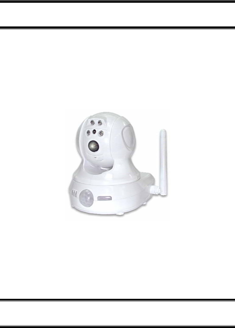
The Network Camera has an Integrated Microcomputer and a high quality CMOS digital-
Image-Sensor, enabling it to display high quality live streaming video over your wired LAN,
the Internet, and for the Network Camera, an 802.11g Wireless LAN.
Using enhanced MPEG-4 technologies, the Network Camera is able to stream high quality
video and audio directly to your PC. The high compression capabilities of MPEG-4 reduce
network bandwidth requirements to amazingly low levels.
With built-in PIR sensor and White Light LEDs, the Network camera can provide home
security and illumination around 5 meters long under low light conditions in a simple,
economical manner.
A convenient and user-friendly Windows program is provided for both viewing and recording
video. If necessary, you can even view video using your Web Browser, on a variety of software
platforms.
Figure 1: Network Camera
Features
• Standalone Design. The Network Camera is a standalone system with built-in CPU and
Video encoder. It requires only a power source and a connection to your LAN or Wireless
LAN.
1

2
• Dual Video Support. The Network Camera can support both MEPG4 and MJEPG video
for different image compression.
• Stream Live Video to Multiple Users. The MPEG4 encoder and HTTP server built
into the camera generate a ready-to-view video stream. Just connect to the camera using
your Web browser or the provided Windows utility to view live video.
• Suitable for Home, Business or Public Facilities. Whether for Home, Business or
Public Facility surveillance, or just for entertainment and fun, the Network Camera has the
features you need.
• Multi-Protocol Support. Supporting TCP/IP networking, SMTP (E-mail), HTTP and
other Internet related protocols, the Network Camera can be easily integrated into your
existing network.
• Easy Configuration. A Windows-based Wizard is provided for initial setup.
Subsequent administration and management can be performed using a standard web
browser. The administrator can configure and manage the Network Camera via the LAN
or Internet.
• Viewing/Recording Utility. A user-friendly Windows utility is provided for viewing
live video. For periods when you are absent, or for scheduled recording, this application
also allows you to record video to an ASF file on your PC. The recorded files are in a
standard Windows Media format, and thus usable by a wide variety of programs if
required.
• Motion Detection. This feature can detect motion in the field of view. The Network
Camera will compare consecutive frames to detect changes caused by the movement of
large objects. This function only works indoors due to the sensitivity of the CMOS sensor.
When motion is detection, an E-mail alert can be sent, or some other action may be
triggered.
• Flexible Scheduling. You can limit access to the video stream to specified times using
a flexible scheduling system. The Motion Detection feature can also have its own schedule,
so it is active only when required.
• Syslog Support. If you have a Syslog Server, the Network Camera can send its log data
to your Syslog Server.
• Audio Support. You can listen as well as look! Audio is encoded with the video if
desired. You can use either the built-in microphone or an external microphone.
• PIR (Passive Infrared Sensor) Support. The Network Camera is embedded with an
PIR Sensor, which senses infrared light radiating from human bodies in its field of view.
This feature is very helpful in enhancing home security systems.
• White Light LEDs Support. Each Network Camera has 4 white light LEDs. The LEDs
can provide illumination around 5 meters long, that can help to output a better video
quality while under low-light conditions such as indoors, on cloudy days, or in the
morning or evening. The white light can be used to deliver warning as well.
Internet Features
• User-definable HTTP port number. This allows Internet Gateways to use "port
mapping" so the Network Camera and a Web Server can share the same Internet IP
address.
• SMB Client Support. With Server Message Block Protocol (SMB protocol) support, the
client applications in a computer can read, create, and update files on the remote server.
• DDNS Support. In order to view video over the Internet, users must know the Internet
IP address of the gateway used by the Network Camera. But if the Gateway has a dynamic
IP address, DDNS (Dynamic DNS) is required. Since many existing Gateways do not
support DDNS, this function is incorporated into the Network Camera.

3
• NTP (Network-Time-Protocol) Support. NTP allows the Network Camera to
calibrate its internal clock from an Internet Time-Server. This ensures that the time stamp
on Video from the Network Camera will be correct.
Security Features
• User Authentication. If desired, access to live video can be restricted to known users.
Users will have to enter their username and password before being able to view the video
stream. Up to 10 users can view the video simultaneously.
• Password-Protected Configuration. Configuration data can be password protected, so
that it only be changed by the Network Camera Administrator.
Wireless Features (Wireless Model Only)
• Standards Compliant. The Network Camera complies with the IEEE802.11g (DSSS)
specifications for Wireless LANs.
• Supports both 802.11b and 802.11g Standards. The Network Camera supports both
802.11b and 802.11g standards.
• Speeds to 54Mbps. All speeds up to the 802.11g maximum of 54Mbps are supported.
• Wired and Wireless Network Support. The Network Camera supports either wired or
wireless transmission.
• WEP Support. Full WEP support (64/128 Bit) on the Wireless interface is provided.
• WPA/WPA2 Support. The WPA Personal/WPA2 Personal standard is also supported,
allowing advanced encryption of wireless data.
• WPS Support. WPS (Wi-Fi Protected Setup) can simplify the process of connecting any
device to the wireless network by using the push button configuration (PBC) on the
Wireless Access Point, or entering a PIN code if there's no button.
4
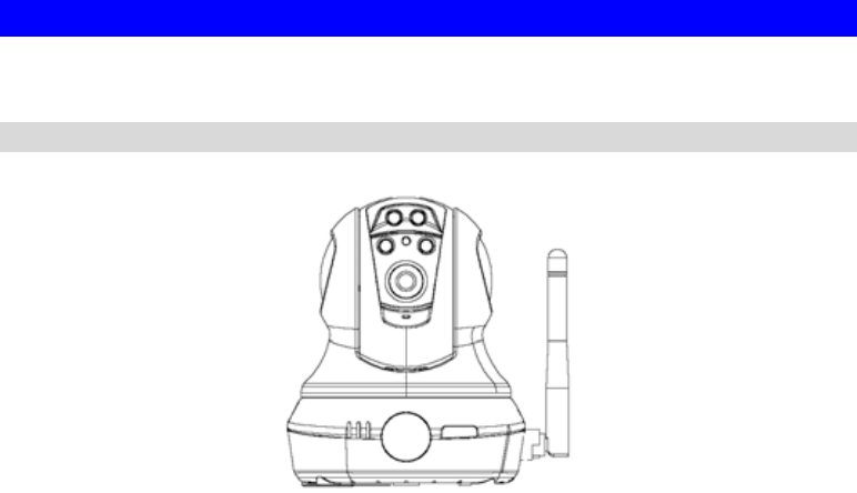
Physical Details - Network Camera
Front - Network Camera
Figure 2: Front Panel
White Light LEDs These white LEDs are designed for the supply of backlighting while
under the low-light environments.
Light Sensor The light sensor can be used to distinguish between light and dark,
as well as determine the intensity of the light.
Echo Cancellation Echo cancellation can reduce background noise and remove hybrid
to provide better voice quality.
Lens No physical adjustment is required or possible for the lens, but you
should ensure that the lens cover remain clean. The image quality is
degraded if the lens cover is dirty or smudged.
Microphone The built-in microphone is mounted on the front.
Power LED
(Green) On - Power on.
Off - No power.
Blinking - The Power LED will blink during start up. This will take
15 to 20 seconds.
Active LED
(Green) Off - No user is viewing the camera.
Blinking - User(s) is viewing the camera.
Network LED
(Green, Amber) On (Green) - Wireless or LAN connection is available.
Off - Wireless or LAN is not connected or camera is not
sending/receiving data.
Blinking (Green) - Data is being transmitted or received via the
LAN or Wireless connection.
On (Amber) - If the LED is on for 5 seconds, the WPS is not
processing successfully.
Blinking (Amber) - WPS function is being processed.
PIR Sensor The PIR sensor is designed for human body detection.
5
Privacy Button On (Green) - The privacy button is in use.
Off - The privacy button is not activated.
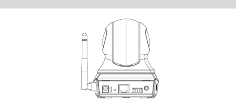
Rear - Network Camera
Figure 3: Rear Panel
Antenna Attach the supplied antenna here. The antenna is adjustable; best
results are usually obtained with the antenna positioned vertically.
Power Input Connect the supplied 5V power adapter here. Do not use other
power adapters; doing so may damage the camera.
Reset Button This button is recessed; you need a pin or paper clip can be used to
depress it. It can be activated at any time the camera is in the
"ready" mode.
• Reset to manufacturer default valued and reboot. When
pressed and held over 10 seconds, the settings of Network
Camera will be set to their default values.
Note:
After this procedure is completed, all LEDs will blink three times to
confirm that the reset was completed successfully.
WPS Button
(Wireless Model
Only)
Push the WPS button on the device and on your other wireless
device to perform WPS function that easily creates an encryption-
secured wireless connection automatically.
• WPS PBC Mode. When pressed and released (less then 3
seconds), the Network Camera will be in the WPS PBC mode
(Auto link mode).
• WPS Pin Code Mode. When pressed and held for over 3
seconds (less than 10 seconds), the Network Camera will be in
the WPS Pin Code mode.

6
LAN port Use a standard LAN cable to connect your Network Camera to a
10/100BaseT hub or switch.
Note:
• Plugging in the LAN cable will disable the Wireless interface.
Only 1 interface can be active at any time.
• The LAN cable should only be connected or disconnected when
the camera is powered OFF. Attaching or detaching the LAN
cable while the camera is powered on does NOT switch the
interface between wired and wireless.
Digital
Input/Output The GPIO terminal block includes 1 input port and 1 output port.
Speaker out If required, an external speaker can be plugged in here.
Package Contents
The following items should be included: If any of these items are damaged or missing, please
contact your dealer immediately.
1. Network Camera
2. Antenna (Wireless Model Only)
3. Power adapter
4. Installation CD-ROM
5. Quick Installation Guide

7
Chapter 2
Basic Setup
This Chapter provides details of installing and configuring the Network
Camera.
System Requirements
• To use the wired LAN interface, a standard 10/100BaseT hub or switch and network cable
is required.
• To use the Wireless interface on the wireless model, other Wireless devices must be
compliant with the IEEE802.11b or IEEE802.11g specifications. All Wireless stations
must use compatible settings.
The default Wireless settings are:
Mode: Infrastructure
SSID: ANY
Wireless Security: Disabled
Domain: USA (USA Area)
Eu (Europe Area)
Channel No.: Auto
2

8
Installation - Network Camera
1. Assemble the Camera
Screw the supplied antenna to the mounting point on the rear.
Attach the Camera Mount to the camera.
2. Connect the LAN Cable
Connect the Network Camera to a 10/100BaseT hub or switch, using a standard LAN
cable.
For the Wireless Model, this will disable the Wireless Interface.
The Wireless and LAN interfaces cannot be used
simultaneously. Using the LAN interface is recommended for
initial configuration. After the Wireless settings are correct,
the Wireless interface can be used.
The first time you connect to the camera, you should connect
the LAN cable and configure the Network Camera with
appropriate settings. Then you can unplug the LAN cable and
power off the camera. The Network Camera will be in wireless
interface when you power on the camera again.
3. Power Up
Connect the supplied 5Vpower adapter to the Network Camera and power up. Use only the
power adapter provided. Using a different one may cause hardware damage.
4. Check the LEDs
• The Power LED will turn on briefly, then start blinking. It will blink during startup, which
takes 15 to 20 seconds. After startup is completed, the Power LED should remain ON.
• The Network LED should be ON.
For more information, refer to Physical Details - Network Camera in Chapter 1.
NOTE: Do not force the Pan/Tilt part of the Network Camera to twist, otherwise it may
cause internal gear set damages.
9
Setup using the Windows Wizard
Initial setup should be performed using the supplied Windows-based setup Wizard. This
program can locate the Network Camera even if its IP address is invalid for your network. You
can then configure the Network Camera with appropriate TCP/IP settings for your LAN.
Subsequent administration can be performed with your Web browser, as explained in Chapter
5 - Web-based Management.
Setup Procedure
1. Insert the supplied CD-ROM into your drive. If the setup program does not start
automatically, run NetworkCamera.exe in the root folder.
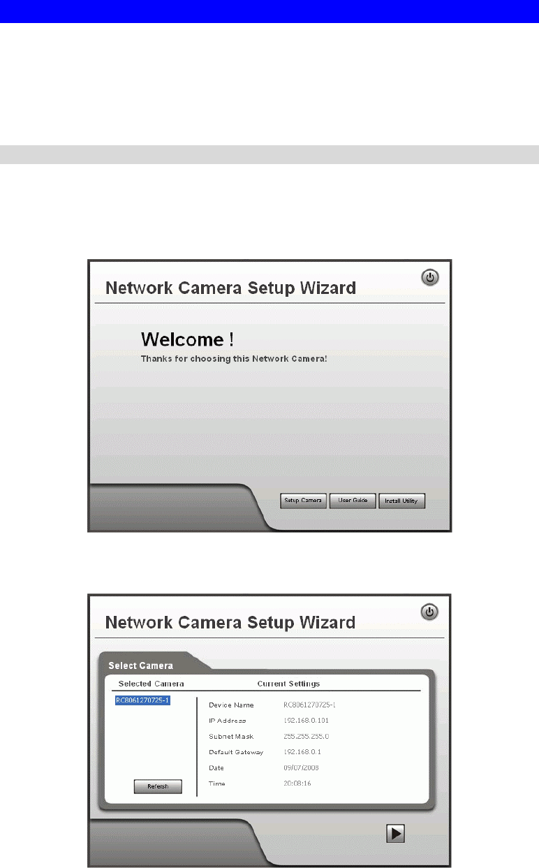
• You will see the Welcome screen shown below.
• Click the Setup Camera button to start the setup Wizard
Figure 4: Welcome Screen
2. The next screen, shown below, will list all the Network Cameras on your LAN.
Figure 5: Camera List Screen
10
• Select the desired Camera from the list on the left. The current settings for the selected
Camera will be displayed in the table on the right.
• Click Next to continue.
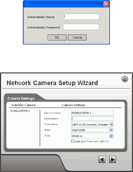
3. You will be prompted to enter the Administrator Name and Administrator Password, as
shown below.
• If using the default values, enter administrator for the name, and leave the
password blank.
• Otherwise, enter the Administrator Name and Administrator Password set on the
Maintenance screen.
Figure 6: Password Dialog
4. This screen allows you to enter a suitable Description, and set the correct Time Zone,
Date, and Time. Make any desired changes, then click Next to continue.
Figure 7: Camera Settings
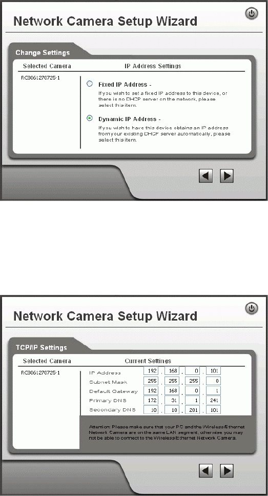
5. On the following IP Address Settings screen, shown below, choose Fixed IP Address or
Dynamic IP Address.
11
Figure 8: Fixed or Dynamic IP Selection
• Fixed IP Address is recommended, and can always be used.
• Dynamic IP Address can only be used if your LAN has a DCHP Server.
Click Next to continue.
6. If you chose Fixed IP Address, the following TCP/IP Settings screen will be displayed.
Figure 9: TCP/IP Settings
• Enter an unused IP Address from within the address range used on your LAN.
• The Subnet Mask and Default Gateway fields must match the values used by PCs on
your LAN.
• The Primary DNS address is required in order to use the E-mail alert or Dynamic
DNS features. Enter the DNS (Domain Name Server) address recommended by your
ISP.
• The Secondary DNS is optional. If provided, it will be used if the Primary DNS is
unavailable.
Click Next to continue.
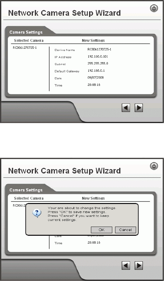
7. The next screen, shown below, displays all details of the Network Camera.
12
• Click Next if the settings are correct
• Click Back to modify any incorrect values.
Figure 10: Save Settings
8. Click OK to confirm that you want to save the new settings. If you want to cancel your
changes, click Cancel.
Figure 11: Confirm Screen
9. After clicking OK, you will see the screen below.
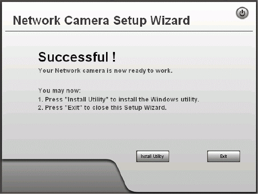
13
Figure 12: Final Screen
Clicking the Install Utility button will install the Viewing/Recording utility described in
Chapter 6 - Windows Viewing/Recording Utility.
10. Click Exit to end the Wizard.
Setup is now complete.

14
Chapter 3
Viewing Live Video
This Chapter provides basic information about viewing live video.
Overview
After finishing setup via the Windows-based Wizard, all LAN users can view live video using
Internet Explorer on Windows.
This Chapter has details of viewing live video using Internet Explorer.
But many other powerful features and options are available:
• To view multiple cameras simultaneously, or record video (either interactively or by
schedule), you should install the Windows Viewing/Recording utility. Refer to Chapter 6 -
Windows Viewing/Recording Utility for details on installing and using this program.
• The camera administrator can also adjust the Video Stream, and restrict access to the video
stream to known users by requiring viewers to supply a username and password. See
Chapter 4 - Advanced Viewing Setup for details.
• To make Live Video from the camera available via the Internet, your Internet Gateway or
Router must be configured correctly. See Making Video available from the Internet in
Chapter 4 - Advanced Viewing Setup for details.
Requirements
To view the live video stream generated by the Network Camera, you need to meet the
following requirements:
• Windows 2000, Windows XP.
• Internet Explorer 6 or later.
Connecting to a Camera on your LAN
To establish a connection from your PC to the Network Camera:
1. Use the Windows utility to get the IP address of the Network Camera.
2. Start Internet Explorer.
3. In the Address box, enter "HTTP://" and the IP Address of the Network Camera.
4. When you connect, the following screen will be displayed.
3
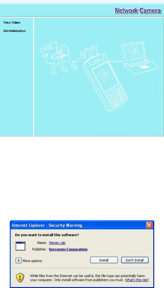
15
Figure 13: Home Screen
5. Click View Video.
6. If the Administrator has restricted access to known users, you will then be prompted for a
username and password.
Enter the name and password assigned to you by the Network Camera administrator.
7. The first time you connect to the camera, you will be prompted to install an ActiveX
component (OCX or CAB file), as in the example below.
You must install this ActiveX component (OCX or CAB file) in order to view the
Video stream in Internet Explorer.
Click the "Yes" button to install the ActiveX component.
Figure 14: ActiveX OCX Prompt
8. Video will start playing automatically. There may be a delay of a few seconds while the
video stream is buffered.

16
Connecting to a Camera via the Internet
You can NOT connect to a camera via the Internet unless the camera
Administrator has configured both the camera and the Internet Gateway/Router
used by the camera.
See Making Video available from the Internet in Chapter 4 - Advanced Viewing Setup for
details of the required configuration.
Also, you need a broadband Internet connection to view video effectively. Dial-up connections
are NOT supported.
To establish a connection from your PC to the Network Camera via the Internet:
1. Obtain the following information from the Administrator of the camera you wish to
connect to:
• Internet IP Address or Domain Name of the camera.
• Port number for HTTP connections.
• Login (username, password) if required.
2. Start Internet Explorer.
3. In the Address box, enter the following:
HTTP://Internet_Address:port_number
Where Internet_Address is the Internet IP address or Domain Name of the camera,
and port_number is the port number used for HTTP (Web) connections to the camera.
Examples using an IP address:
HTTP://203.70.212.52:1024
Where the Internet IP address is 203.70.212.52 and the HTTP port number is 1024.
Example using a Domain Name:
HTTP://mycamera.dyndns.tv:1024
Where the Domain name (using DDNS in this example) is mycamera.dyndns.tv and
the HTTP port number is 1024.
17
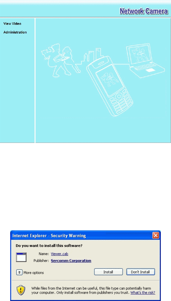
4. When you connect, the following screen will be displayed.
Figure 15: Home Screen
5. Click View Video.
6. If the Administrator has restricted access to known users, you will then be prompted for a
username and password.
Enter the name and password assigned to you by the Network Camera administrator.
7. The first time you connect to the camera, you will be prompted to install an ActiveX
component (OCX or CAB file), as in the example below.
You must install this ActiveX component (OCX or CAB file) in order to view the
Video stream in Internet Explorer.
Click the "Yes" button to install the ActiveX component.
Figure 16: ActiveX OCX Prompt
8. Video will start playing automatically. There may be a delay of a few seconds while the
video stream is buffered.
18
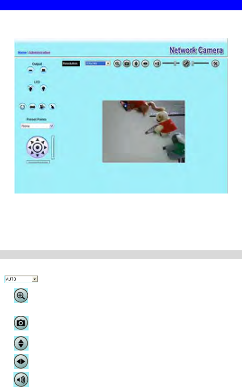
Viewing Live Video
After installing the ActiveX component, you will be able to view the live video stream in its
own window, as shown below.
Figure 17: View Video Screen
There are a number of options available on this screen, accessed by select list, button or icon.
See the table below for details.
Note: The options can only be configured while using IE browser. Other browsers can just
view the video rather than configuration.
General Options
These options are always available, regardless of the type of camera you are connected to.
Resolution. Use this drop-down list to select the desired video size.
Zoom. A digital zoom feature is available. To zoom in on a section of the
window, click this icon. Then use your mouse to select the section you want
to magnify. Click the icon again to disable the zoom feature.
Snapshot. Click this to take a single JPEG "snapshot" image of the current
video.
Flip. Click this to have the image swapped top-to-bottom.
Mirror. Click this to have the image swapped left-to-right.
Audio On. This icon is displayed if audio is On. Click on the icon to turn
audio Off.

19
Speaker On. This icon is displayed if speaker is On. Click on the icon to
turn speaker Off.
Volume. If audio is enabled, use this slider to adjust the volume.
Setup. Select the desired video format from the drop-down list.
ON. Click this to set the output I/O port to ON mode.
OFF. Click this to set the output I/O port to OFF mode.
LED ON. Click this to turn on the White LEDs.
LED OFF. Click this to turn off the White LEDs.
Camera Patrol. Move through the Preset positions in the sequence defined
by the Camera Administrator.
Camera Auto Pan. Click this to have the camera moved from left to right
automatically.
Motion Detection. Click this button to have the camera moved to the
Motion Detection Preset position.
Direct P/T. Use this to move the camera to the Pan/Tilt position directly.
Preset Points. Select the desired Preset points.
Move Control. Use this to move the camera to the desired position. There
may a short delay after clicking the desired icon. You should wait a couple
of seconds rather than click again.
Or you can drag the vertical or horizontal slider bar to have quicker
movement of the Network Camera to the desired position.

20
Chapter 4
Advanced Viewing Setup
This Chapter provides information about the optional settings and features for
viewing video via the Network Camera. This Chapter is for the Camera
Administrator only.
Introduction
This chapter describes some additional settings and options for viewing live Video:
• Adjusting the video image
• Controlling user access to the live video stream
• Making video available from the Internet
• Using the Motion Detection feature
Adjusting the Video Image
If necessary, the Network Camera Administrator can adjust the Video image.
To Adjust the Video Image:
1. Connect to the Web-based interface of the Network Camera. (See Chapter 5 - Web-based
Management for details.)
2. Select Administration, then Video & Audio. You will see a screen like the example below.
Figure 18: Video & Audio Screen
3. Make the required adjustments, as explained below, and save your changes.
4

21
MPEG-4 Settings
Resolution Select the desired video resolution format. The default resolution is
set to 320*240.
Video Quality
Control
• Constant Bit Rate: Select the desired bit rate. The default is set
to 256 Kbps.
• Fixed Quality: Select the desired option. The default fix quality
is set to Normal.
Max. Frame Rate Select the desired Maximum bandwidth for the video stream. Note
that you can specify EITHER the Bandwidth OR the Frame Rate,
not both. If the Bandwidth is defined, the frame rate will be adjusted
as necessary to achieve the specified frame rate.
The default values for bandwidth is 30.
MJPEG Settings
Resolution Select the desired video resolution format. The default resolution is
set to 320*240.
Fixed Video
Quality Select the desired fix quality. The default fix quality is set to
Normal.
Max. Frame Rate Select the desired Maximum bandwidth for the video stream. Note
that you can specify EITHER the Bandwidth OR the Frame Rate,
not both. If the Bandwidth is defined, the frame rate will be adjusted
as necessary to achieve the specified frame rate.
The default value for bandwidth is 30.
Mobil Settings
Enable Mobil
Streaming Enable streaming video for the mobile device by checking this
checkbox.
Resolution The default resolution is set to 160x120.
Video Quality
Control
• Constant Bit Rate: Select the desired fix bit rate.
• Fixed Quality: Select the desired option. The default fix quality
is set to Normal.
Max. Frame Rate Select the desired Maximum bandwidth for the video stream.
Access Code Enter the 8 digit code (0~9) for accessing the live video from camera
through cell phone connection.
Video Adjustment
Power Line
Frequency Select the power line frequency (50Hz or 60Hz) used in your region,
to improve the picture quality under florescent lighting.
White Balance Select the desired option to match the current environment and
lighting.
Brightness If necessary, you can adjust the brightness to obtain a better image.
For example, if the camera is facing a bright light, the image may be
too dark. In this case, you can increase the brightness.
Sharpness Select the desired option for the sharpness. You can select a
Sharpness value between -3 and 3.

22
Options
Microphone Enable audio by checking this checkbox. Using Audio will increase
the bandwidth requirements slightly.
Audio Type Select the desired audio type.
Speaker Enable speaker sound by checking this checkbox.
Flip This setting will have the image swapped top-to-bottom.
Mirror This setting will have the image swapped left-to-right.
Time Stamp If enabled, the current time will be displayed on the Video image.
Text Display Enable this setting if you want text to be displayed on the Video
image, and enter the desired text - up to 20 characters. This feature
is often used to identify each camera when multiple cameras are
installed.
White Light LEDs If the checkbox is enabled, the white light LEDs will be turned on
when the surrounding light is below 0.5 lux and Trigger Event
option in the event trigger screen is enabled.
23
Viewing the live Video on your cell phone
The live streaming of the Network Camera can even be viewed from a compatible cell phone,
so you can keep an eye on things almost everywhere you go. It’s just as easy as following the
required steps.
To Adjust the Mobile Settings
1. Connect to the Web-based interface of the Network Camera. (See Chapter 5 - Web-based
Management for details.)
2. Select Administration, then Video & Audio. You will see a screen like the example below.
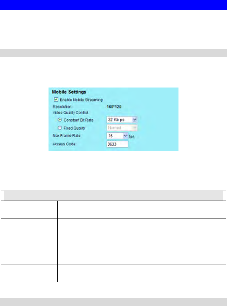
Figure 19: Mobile Settings
3. Check the checkbox of Enable Mobile Streaming and configure the related settings in the
Mobile Settings section, as explained below. Save your changes.
Mobil Settings
Enable Mobil
Streaming Enable streaming video for the mobile device by checking this
checkbox.
Resolution The default resolution is set to 160x120.
Video Quality
Control
• Constant Bit Rate: Select the desired fix bit rate.
• Fixed Quality: Select the desired option. The default fix quality
is set to Normal.
Max. Frame Rate Select the desired Maximum bandwidth for the video stream.
Access Code Enter the code for accessing the live video from camera through cell
phone connection.
Connecting Cell Phone to the Network Camera
A number of different mobile handsets are compatible with the Network Camera. Follow the
suggested steps (steps may differ according to the mobile phone you use).
Before connecting to the cell phone, please make sure the following:
• Mobile phone should be supported by 3GPP protocol.
• Camera Web management - RTSP port number in the Network screen needs to be entered.
Default is 554.
• Access code: 8 digits (0~9)
24
Steps :
1. Start IE
2. Select Add Bookmark
3. Click Edit
4. Enter desired value for Subject or leave it blank
5. Enter the camera’s IP address into the Address box.
RTSP://Internet_Address/Access_code
6. Click Play
25
Controlling User Access to the Video Stream
By default, anyone can connect to the Network Camera and view live Video at any time.
If desired, you can limit access to scheduled times, and also restrict access to known users.
To Control User Access to Live Video:
1. Connect to the Web-based interface of the Network Camera. (See Chapter 5 - Web-based
Management for details.)
2. Select Administration, then Video Access.
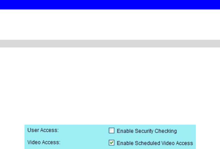
3. Set the desired options for Access.
Access
If the Video Access is disabled, users cannot connect using either their Web Browser or the
Windows utility. However, viewing video is still possible by logging in as the Administrator.
Figure 20: Controlling User Access
See Chapter 5 - Web-based Management for further details about using the Video Access and
User Database screens.
26
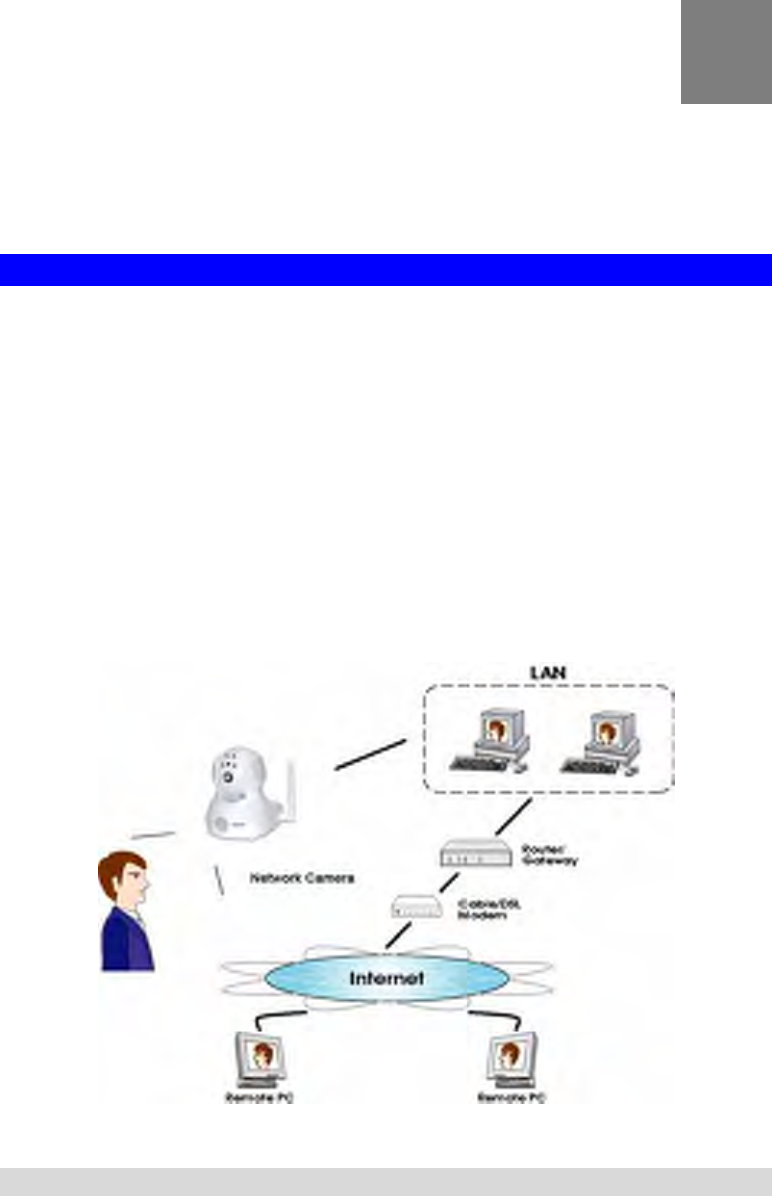
Making Video available from the Internet
If your LAN is connected to the Internet, typically by a Broadband Gateway/Router and
Broadband modem, you can make the Network Camera available via the Internet. You will
need to configure your Router or Gateway to allow connections from the Internet to the camera.
Router/Gateway Setup
Your Router or Gateway must be configured to pass incoming TCP (HTTP) connections (from
Internet Viewers) to the Network Camera. The Router/Gateway uses the Port Number to
determine which incoming connections are intended for the Network Camera.
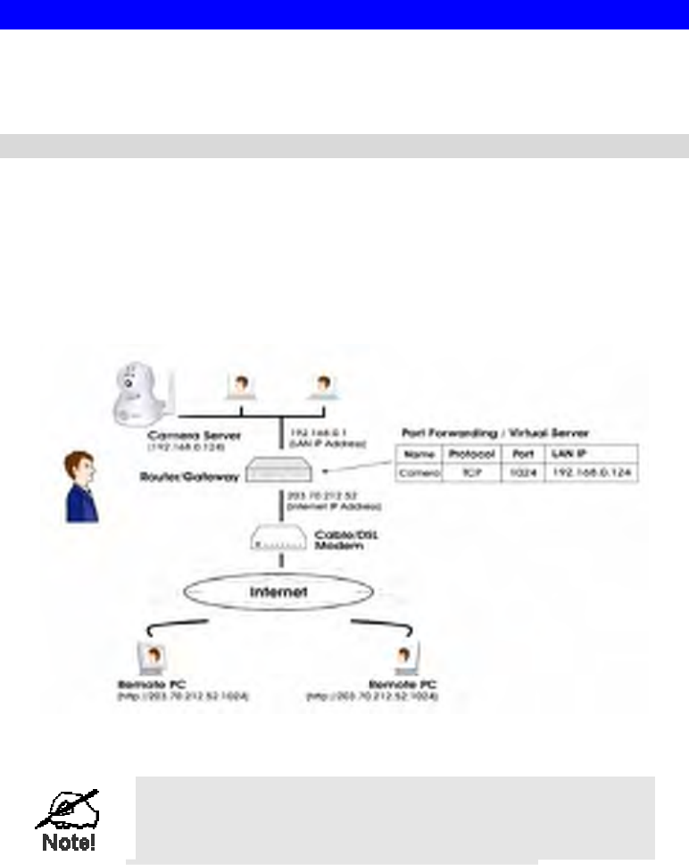
This feature is normally called Port Forwarding or Virtual Servers, and is illustrated below.
The Port Forwarding/Virtual Server entry tells the Router/Gateway that incoming TCP
connections on port 1024 should be passed to the Network Camera. If necessary, check the
user manual for your Router/Gateway for further details.
Figure 21: Connecting via the Internet
The "Port" for the Port Forwarding / Virtual Server entry
above is the " Secondary Port" number specified on the
Network screen of the Network Camera.
27
Network Camera Setup
The Network Camera configuration does NOT have be changed, unless:
• You wish to change the port number from the default value (1024).
• You wish to use the DDNS (Dynamic DNS) feature of the Network Camera.
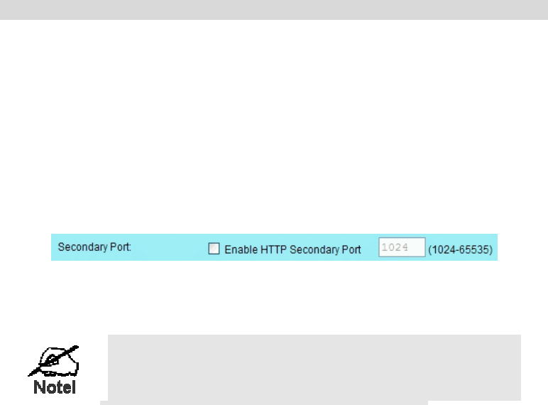
HTTP Port Configuration
Normally, HTTP (Web) connections use port 80. Since the Network Camera uses HTTP, but
port 80 is likely to be used by a Web Server, you can use a different port for the Network
Camera. This port is called the Secondary Port.
The default Secondary Port is 1024. If you prefer to use a different port number, you can
specify the port number on the Network Camera's Network screen, as shown below.
Figure 22: Network Screen
See Chapter 5 - Web-based Management for further details on using the Network screen.
Viewers need to know this port number in order to connect
and view live Video, so you must inform viewers of the
correct port number.
DDNS (Dynamic DNS)
Many internet connections use a "Dynamic IP address", where the Internet IP address is
allocated whenever the Internet connection is established.
This means that other Internet users don't know the IP address, so can't establish a connection.
DDNS is designed to solve this problem, by allowing users to connect to your LAN using a
domain name, rather than an IP address.
To use DDNS:
1. Register for the DDNS service with a supported DDNS service provider. You can then
apply for, and be allocated, a Domain Name.
2. Enter and save the correct DDNS settings on the DDNS screen of the Network Camera.
3. Both Router and Camera should use the same port number for DDNS service.
28
Figure 23: DDNS Screen
4. Operation is then automatic:
• The Network Camera will automatically contact the DDNS server whenever it detects
that the Internet IP address has changed, and inform the DDNS server of the new IP
address.
• Internet users can then connect to the camera using the Domain Name allocated by the
DDNS service provider.
Example: http://normanyu123456789.dyndns.org:6016
normanyu123456789.dyndns.org is domain host name. 6016 is the port number.
29
Viewing Live Video via the Internet
Clients (viewers) will also need a broadband connection; dial-up connections are NOT
recommended.
Viewing Live Video Using your Web Browser
If using your Web browser, you need to know the Internet IP address (or the Domain name) of
the camera's Router/Gateway, and the correct port number.
Enter the Internet address of the Router/Gateway, and its port number, in the Address (or
Location) field of your Browser.
Example - IP address:
HTTP://203.70.212.52:1024
Where the Router/Gateway's Internet IP address is 203.70.212.52 and the "Secondary
Port" number on the Network Camera is 1024.
Example - Domain Name:
HTTP://mycamera.dyndns.tv:1024
Where the Router/Gateway's Domain name is mycamera.dyndns.tv and the "Secondary
Port" number on the Network Camera is 1024.
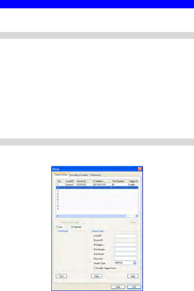
Viewing Live Video with the Viewing/Recording Utility
If using the Windows Viewing/Recording Utility, the details of the Network Camera must be
entered on the Camera Setup screen.
Figure 24: Add Camera from Internet
See Chapter 6 - Window Viewing/Recording Utility for full details on using the Windows
Viewing/Recording utility.
30
Motion Detection Alerts
The Motion Detection feature can generate an Alert when motion is detected.
The Network Camera will compare consecutive frames to detect changes caused by the
movement of large objects.
But the motion detector can also be triggered by:
• Sudden changes in the level of available light
• Movement of the camera itself.
Try to avoid these situations. The motion detection feature works best in locations where there
is good steady illumination, and the camera is mounted securely. It cannot be used outdoors
due to the sensitivity of the CMOS sensor.
Note: The Motion Detection settings can only be configured while using IE browser.
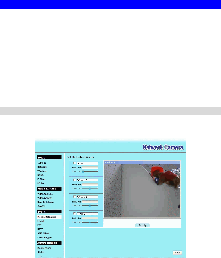
To Use Motion Detection Alerts
Using the Web-based interface on the Network Camera, select the Motion Detection screen,
then configure this screen as described below.
Figure 25: Motion Detection
1. Enable the Motion Detection feature.
2. Set the area or areas of the video image to be examined for movement. You can define up
to 4 areas, and set the motion threshold individually for each area.
3. If using a schedule, define the desired schedule in Event Trigger screen.
4. Save your changes.
5. Select the E-Mail screen to have alerts sent by E-mail:
• Enable and enter at least one (1) E-mail address
• Select or enter the desired options for Video Attachment, Show "From" as and Subject
fields.
• Enter details of the SMTP Server used to send the E-mail.

31
If the Motion Detection feature is enabled, but E-Mail is not
enabled, then the only action when motion is detected is to
log this event in the system log.

32
Chapter 5
Web-based Management
This Chapter provides Setup details of the Network Camera’s Web-based
Interface. This Chapter is for the Camera Administrator only.
Introduction
The Network Camera can be configured using your Web Browser. The Network Camera must
have an IP address which is compatible with your PC.
The recommended method to ensure this is to use the supplied Windows-based Wizard, as
described in Chapter 2 - Basic Setup.
Connecting to Network Camera
• If using only your Web Browser, use the following procedure to establish a connection
from your PC to the Network Camera:
• Once connected, you can add the Network Camera to your Browser's Favorites or
Bookmarks.
Connecting using your Web Browser
1. Use the Windows utility to get the IP address of the Network Camera.
2. Start your WEB browser.
3. In the Address box, enter "HTTP://" and the IP Address of the Network Camera.
4. You will then be prompted for a username and password.
• If using the default values, enter administrator for the name, and leave the
password blank.
• Otherwise, enter the Administrator ID and Administrator Password set on the
Maintenance screen.
5
33
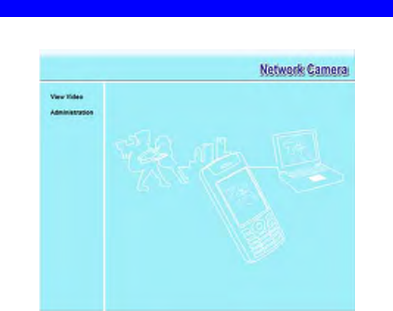
Welcome Screen
When you connect, the following screen will be displayed.
Figure 26: Welcome Screen
The menu options available from this screen are:
• View Video - View live Video using your Web Browser. See Chapter 3 - Viewing Live
Video for details.
• Administration - Access the Administration menu.

34
Administration Menu
Clicking on Administration on the menu provides access to all the settings for the Network
Camera.
The Administration menu contains the following options:
Setup
• System
• Network
• Wireless (Wireless Model Only)
• DDNS
• IP Filter
• I/O Port
Video Stream
• Video & Audio
• Video Access
• User Database
• Pan/Tilt
Event
• Motion Detection
• E-Mail
• FTP
• HTTP
• SMB Client
• Event Trigger
Administration
• Maintenance
• Status
• Log
35
System Screen
After clicking Administration on the main menu, or selecting System on the Administration
menu, you will see a screen like the example below.
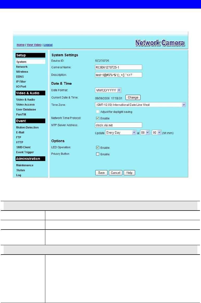
Figure 27: System Screen
Data - System Screen
System Settings
Device ID This displays the ID for the Network Camera.
Camera Name Enter the desired name for the Network Camera.
Description This field is used for entering a description, such as the location of the
Network Camera.
Date & Time
Date Format Select the desired date format, it will also be used to display the date
and time as an overlay on the video image.
The abbreviations used to predefine the date formats are list as follows:
• YYYY-MM-DD = Year-Month-Day, e.g. 2006-01-31
• MM/DD/YYYY = Month/Day/Year, e.g. 01/31/2006
• DD/MM/YYYY = Day/Month/Year, e.g. 31/01/2006

36
Current
Date & Time This displays the current date and time on the camera.
If it's not correct, click the Change button to modify the date/time
settings. This button will open a sub-screen where you have 2 options:
• Set the camera's date and time to match your PC.
• Enter the correct date and time.
Time Zone Choose the Time Zone for your location from the drop-down list.
If your location is currently using Daylight Saving, enable the Adjust
for daylight saving checkbox.
You must UNCHECK this checkbox when Daylight Saving
finishes.
Network Time
Protocol Enable or disable the Time Server feature as required.
If Enabled, the Network Camera will contact a Network Time Server at
regular intervals and update its internal timer.
NTP Server
Address Enter the address for the desired NTP server.
Update The Schedule determines how often the Network Camera contacts the
NTP Server.
Select the desired options.
LED Operation Enable this if you want to use this function.
Privacy Button If Enabled, click the Privacy button will stop uploading the stream
without turning the camera off. Click the button one more time to
continue uploading.
37
Network Screen
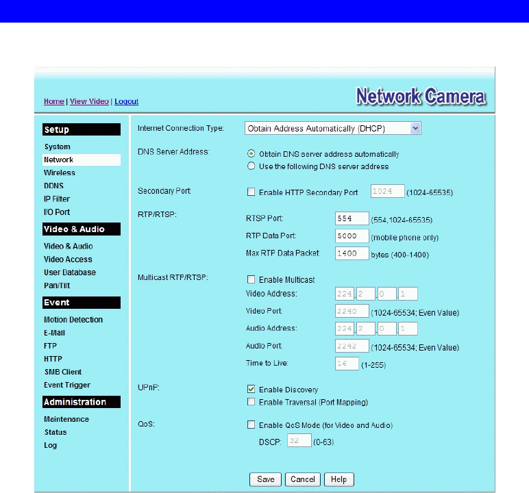
This screen is displayed when the Network menu option is clicked.
Figure 28: Network Screen

38
Data - Network Screen
Network
Internet Connection
Type There are 3 connection types:
• Obtain Address Automatically (DHCP): If selected, the
Network Camera will obtain its IP address and related
information from a DHCP Server. Only select this option if
your LAN has a DHCP Server.
• Static IP Address: If selected, you must assign the following
data to the Network Camera.
• IP Address - Enter an unused IP address from the address
range used on your LAN.
• Subnet Mask - Use the same value as PCs on your LAN.
• Default Gateway - Use the same value as PCs on your
LAN.
• PPPoE (PPP over Ethernet): This is the most common login
method, widely used with DSL modems. Normally, your ISP
will have provided some software to connect and login. This
software is no longer required, and should not be used.
• Username - The user name (or account name) provided by
your ISP.
• Password - Enter the password for the login name above.
Obtain DNS server
address
automatically
If selected, the Network Camera will use the DNS address or
addresses provided by the DHPC server.
This option is only available if the IP address setting is Obtain an
IP address Automatically.
Use the following
DNS server address Primary DNS server - Use the same value as PCs on your LAN.
Normally, your ISP will provide this address.
Secondary DNS server - This is optional. If entered, this DNS will
be used if the Primary DNS does not respond.
Secondary Port This sets the port number for HTTP (Web) connections to the
Camera, whether for administration or viewing video.
The secondary port can be used for DDNS, other service and when
more than 2 cameras are in use.
If enabled, you can connect using either port 80 or the Secondary
port. You must enter the Secondary port number (between 1024 to
65535) in the field provided.
Note that when using a port number which is not 80, you must
specify the port number in the URL. For example, if the Camera's
IP address was 192.168.1.100 and the Secondary port was 1024,
you would specify the URL for the Camera as follows:
http://192.168.1.100:1024

39
RTP/RTSP The RTSP (Real Time Streaming Protocol), a standard for
connected client(s) to control streaming data (MPEG-4) over the
World Wide Web. Enter the RTSP Port number (between 1024 and
65535) in the field provided. The default RTSP Port is 554.
The RTP (Real Time Transport Protocol), an Internet protocol for
transmitting real-time data such as audio and video.
Max RTP Data Packet field will let users limit the size of the file.
Enter the desired value between 400 and 1400.
Note: RTSP and RTP settings are for Mobil phone only.
Multicast RTP/RTSP
Enable Multicast Enable the feature as required.
Video Address Enter the address of video.
Video Port Enter the desired value (between 1024 to 65534) in the field
provided. The number you entered must be even values.
Audio Address Enter the address of the audio.
Audio Port Enter the desired value (between 1024 to 65534) in the field
provided. The number you entered must be even values.
Time to Live Enter the desired length of time, if the packets fail to be delivered
to their destination within. The Time to Live you entered must be
in-between 1 to 255.
UPnP
Enable Discovery If enabled, the Network Camera will broadcast its availability
through UPnP. UPnP compatible systems such as Windows XP will
then be able to detect the presence of the Network Camera.
Enable Traversal If enabled, HTTP, RTP and RTSP ports can be opened to establish
and maintain TCP/IP network connections with the camera that
traverse routers using network address translation (NAT).
QoS
Enable QoS Mode If enabled, the throughput level (for Video and Audio) is
guaranteed through QoS (Quality of Service).
DSCP Enter the desired value of Differentiated Services Code Point
(DSCP). The value must be between 0 to 63.
40
Wireless Screen (Wireless Model Only)
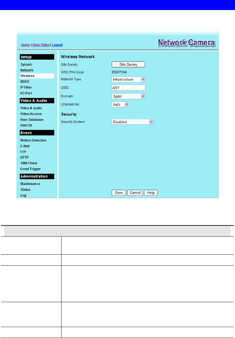
This screen is displayed when the Wireless menu option is clicked.
Figure 29: Wireless Screen
Data - Wireless Screen
Wireless Network
Site Survey Click the "Site Survey" button and select from a list of available
APs.
WSC PIN Code It displays the WSC PIN code number for the camera.
Network Type This determines the type of wireless communication used by the
Network Camera.
• If you have an Access Point, select Infrastructure.
• Otherwise, select Ad-hoc.
SSID This must match the value used by other devices on your wireless
LAN. The Default is ANY.
Note! The SSID is case sensitive.
Domain Select your region from the drop-down list.

41
Channel No. • In Infrastructure mode, this setting is ignored. The Network
Camera will use the Channel set on the Access Point.
• For Ad-hoc mode, select the Channel you wish to use on your
Network Camera. Other Wireless stations should use the same
setting.
• If you experience interference (shown by lost connections
and/or slow data transfers) you may need to experiment with
different channels to see which one is the best.
Security
Security System Select the desired option, and then enter the settings for the selected
method:
• Disabled - No security is used. Anyone using the correct SSID
can connect to your network. This is default.
• WEP - The 802.11b standard. Data is encrypted before
transmission, but the encryption system is not very strong.
• WPA/WPA2 Personal - Like WEP, data is encrypted before
transmission. WPA is more secure than WEP, and should be
used if possible. WPA Personal is the version of WPA which
does NOT require a Radius Server on your LAN.
WEP
Authentication Type Select the appropriate value - "Open System" or "Shared Key".
Check your wireless card's documentation to see what method to
use.
Note: In Infrastructure mode, either setting will normally work,
since most Access Points can use both methods.
WEP Encryption Select the WEP Encryption level:
• 64 Bit Keys (10 Hex chars)
• 128 Bit Keys (26 Hex chars)
• 64 Bit Keys (5 ASCII chars)
• 128 Bit Keys (13 ASCII chars)
Passphrase Enter a word or group of printable characters in the Passphrase box
and click the "Generate Keys" button to automatically configure the
WEP Key(s). If encryption strength is set to 64-bit, then each of the
four key fields will be populated with key values. If encryption
strength is set to 128-bit, then only the selected WEP key field will
be given a key value.
WEP Keys • Use the radio buttons to select the default key.
• Enter the key value you wish to use. Other stations must have
the same key values.
• Keys must be entered in Hex. Hex characters are the digits (0 ~
9) and the letters A ~ F.
• Click Clear Keys to set the Keys to be blank.
WPA/WPA2 Personal
Shared Key Enter the key value. Data is encrypted using a key derived from the
network key. Other Wireless Stations must use the same network
key. The PSK must be from 8 to 63 characters in length.
42
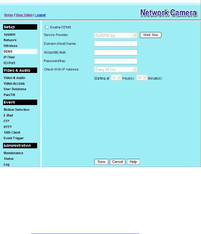
DDNS Screen
Many Internet connections use a "Dynamic IP address", where the Internet IP address is
allocated whenever the Internet connection is established.
This means that other Internet users don't know the IP address, so can't establish a connection.
DDNS is designed to solve this problem, as follows:
• You must register for the DDNS service with a DDNS service provider. The DDNS
Service provider will allocate a Domain Name to you upon request.
• The DDNS settings on the DDNS screen above must be correct.
• The Network Camera will then contact the DDNS server whenever it detects that the
Internet IP address has changed, and inform the DDNS server of the new IP address. (The
Check WAN IP Address determines how often the Network Camera checks if the Internet
IP address has changed.)
This system allows other internet users to connect to you using the Domain Name allocated by
the DDNS service provider.
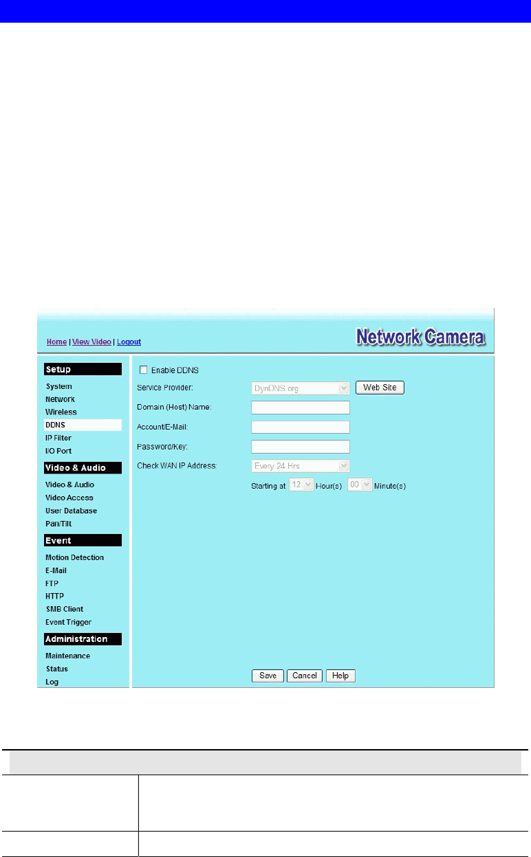
This screen is displayed when the DDNS menu option is clicked.
Figure 30: DDNS Screen
Data - DDNS Screen
DDNS
Enable DDNS Enable or disable the DDNS function, as required.
Only enable this feature if you have registered for the DDNS
Service with a DDNS Server provider.
Service Provider Choose a service provider from the list.

43
Web Site Button Click this button to open a new window and connect to the Web
site for the selected DDNS service provider.
Domain (Host)
Name Enter the Domain Name (Host Name) allocated to you by the
DDNS Server provider.
Account/E-Mail Enter the login name for the DDNS account.
Password/Key Enter the password for the DDNS account.
Check WAN IP
Address Set the schedule for checking if the Internet IP address has
changed. If the IP address has changed, the DDNS Server will be
notified.
NOTE: If the DDNS Service provided some software to perform
this IP address update or notification, you should NOT use this
software. The update is performed by the camera.
44
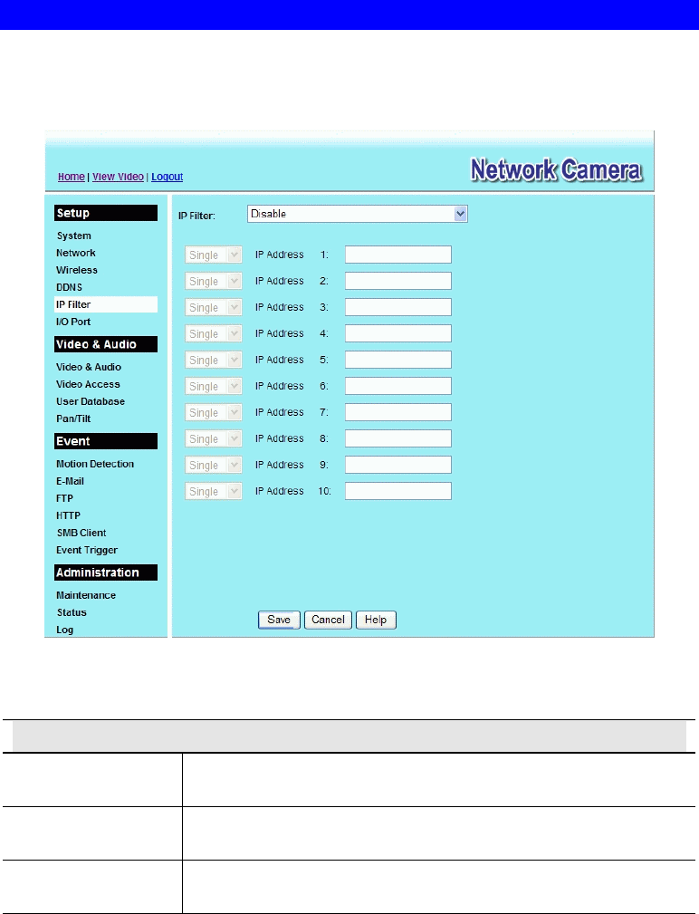
IP Filter
The IP Filter feature allows administrator to control network camera access by filtering IP
addresses. This screen is displayed when the IP Filter menu option is clicked.
Figure 31: IP Filter Screen
Data - IP Filter Screen
IP Filter
IP Filter Select the desired method to perform the IP address(or addresses)
filtering function.
Single/Range Select to perform either single IP address or a range of IP addresses
that you desired.
IP Address Enter an IP address or a range of IP addresses you would like to
allow or deny.
45
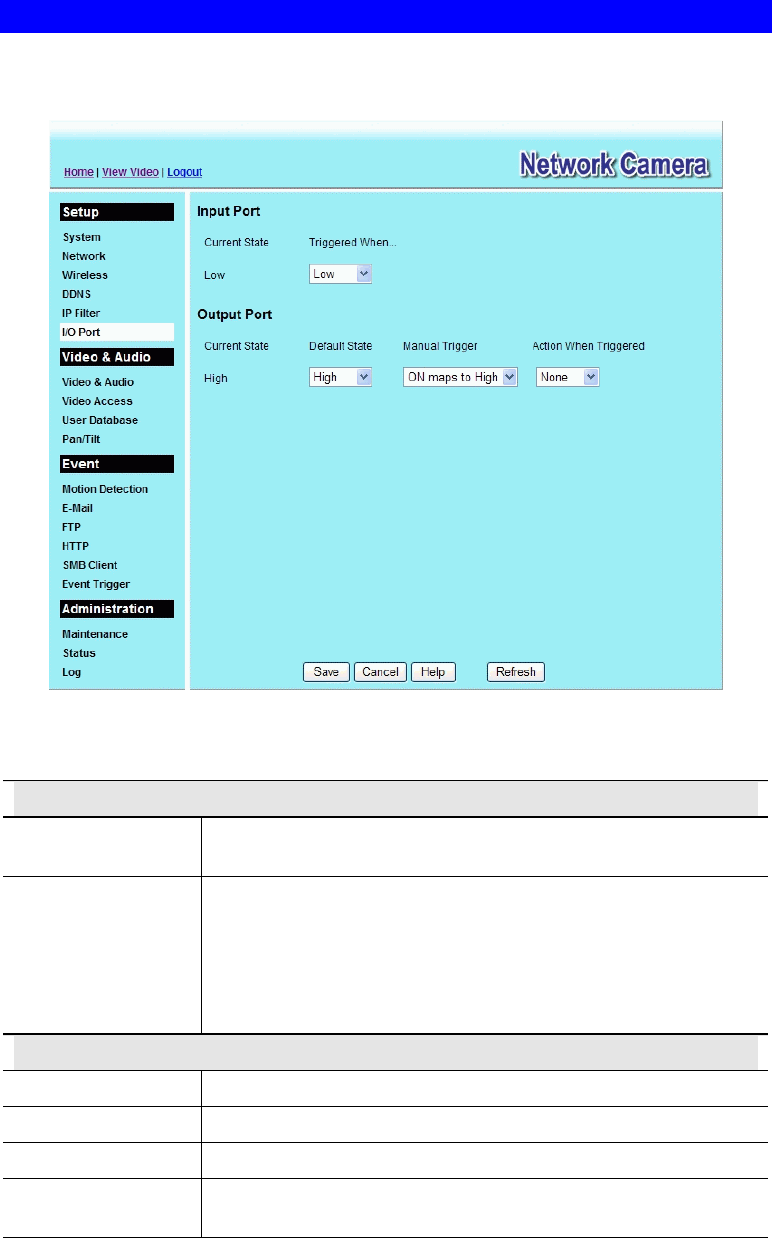
I/O Port
The Network Camera supports 1 input port and 1 output port. This screen is displayed when
the I/O Port menu option is clicked.
Figure 32: I/O Port Screen
Data - I/O Port Screen
Input Ports
Current State It indicates the current state of the input port. Once the configured
state is happened, it will trigger the event actions.
Triggered When… Select the desired State:
• High
• Low
• Rising
• Falling
Output Ports
Current State It indicates the current state of the output port.
Default State Select the desired option from the drop-down list.
Manual Trigger Select the option to control the output state.
Action When
Triggered If an event is happened, it will trigger the event alerting.
46
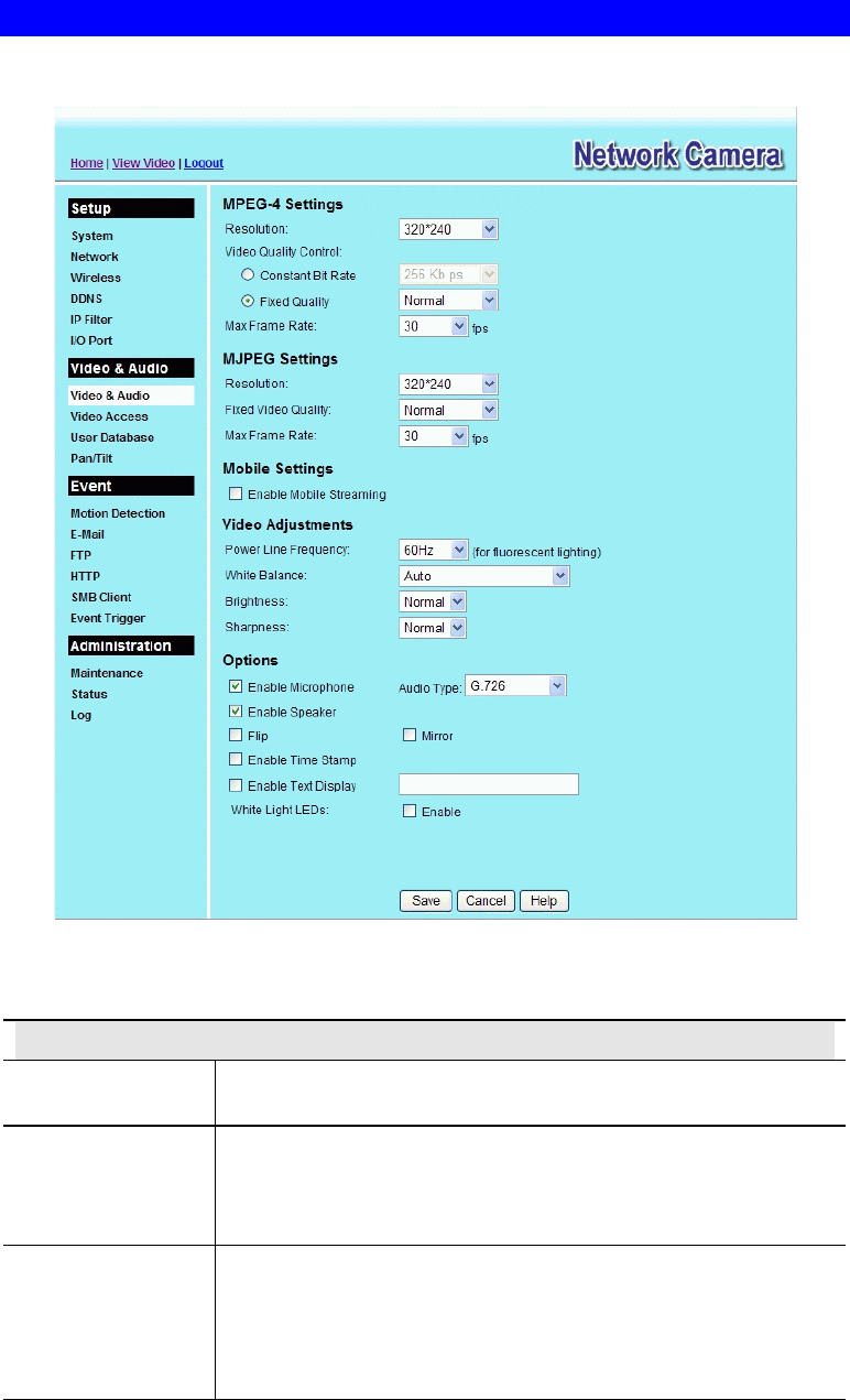
Video & Audio Screen
This screen is displayed when the Video & Audio menu option is clicked.
Figure 33: Video & Audio Screen
Data - Video & Audio Screen
MPEG-4 Settings
Resolution Select the desired video resolution format. The default resolution is
set to 320*240.
Video Quality
Control
• Constant Bit Rate: Select the desired bit rate. The default is set
to 256 Kbps.
• Fixed Quality: Select the desired option. The default fix quality
is set to Normal.
Max. Frame Rate Select the desired Maximum bandwidth for the video stream. Note
that you can specify EITHER the Bandwidth OR the Frame Rate,
not both. If the Bandwidth is defined, the frame rate will be adjusted
as necessary to achieve the specified frame rate.
The default values for bandwidth is 30.

47
MJPEG Settings
Resolution Select the desired video resolution format. The default resolution is
set to 320*240.
Fixed Video
Quality Select the desired fix quality. The default fix quality is set to
Normal.
Max. Frame Rate Select the desired Maximum bandwidth for the video stream. Note
that you can specify EITHER the Bandwidth OR the Frame Rate,
not both. If the Bandwidth is defined, the frame rate will be adjusted
as necessary to achieve the specified frame rate.
The default value for bandwidth is 30.
Mobil Settings
Enable Mobil
Streaming Enable streaming video for the mobile device by checking this
checkbox.
Resolution The default resolution is set to 160x120.
Video Quality
Control
• Constant Bit Rate: Select the desired fix bit rate.
• Fixed Quality: Select the desired option. The default fix quality
is set to Normal.
Max. Frame Rate Select the desired Maximum bandwidth for the video stream.
Access Code Enter the 8 digit code (0~9) for accessing the live video from camera
through cell phone connection.
Video Adjustment
Power Line
Frequency Select the power line frequency (50Hz or 60Hz) used in your region,
to improve the picture quality under florescent lighting.
White Balance Select the desired option to match the current environment and
lighting.
Brightness If necessary, you can adjust the brightness to obtain a better image.
For example, if the camera is facing a bright light, the image may be
too dark. In this case, you can increase the brightness.
Sharpness Select the desired option for the sharpness. You can select a
Sharpness value between -3 and 3.
Options
Microphone Enable audio by checking this checkbox. Using Audio will increase
the bandwidth requirements slightly.
Audio Type Select the desired audio type.
Speaker Enable speaker sound by checking this checkbox.
Flip This setting will have the image swapped top-to-bottom.
Mirror This setting will have the image swapped left-to-right.
Time Stamp If enabled, the current time will be displayed on the Video image.
Text Display Enable this setting if you want text to be displayed on the Video
image, and enter the desired text - up to 20 characters. This feature
is often used to identify each camera when multiple cameras are
installed.