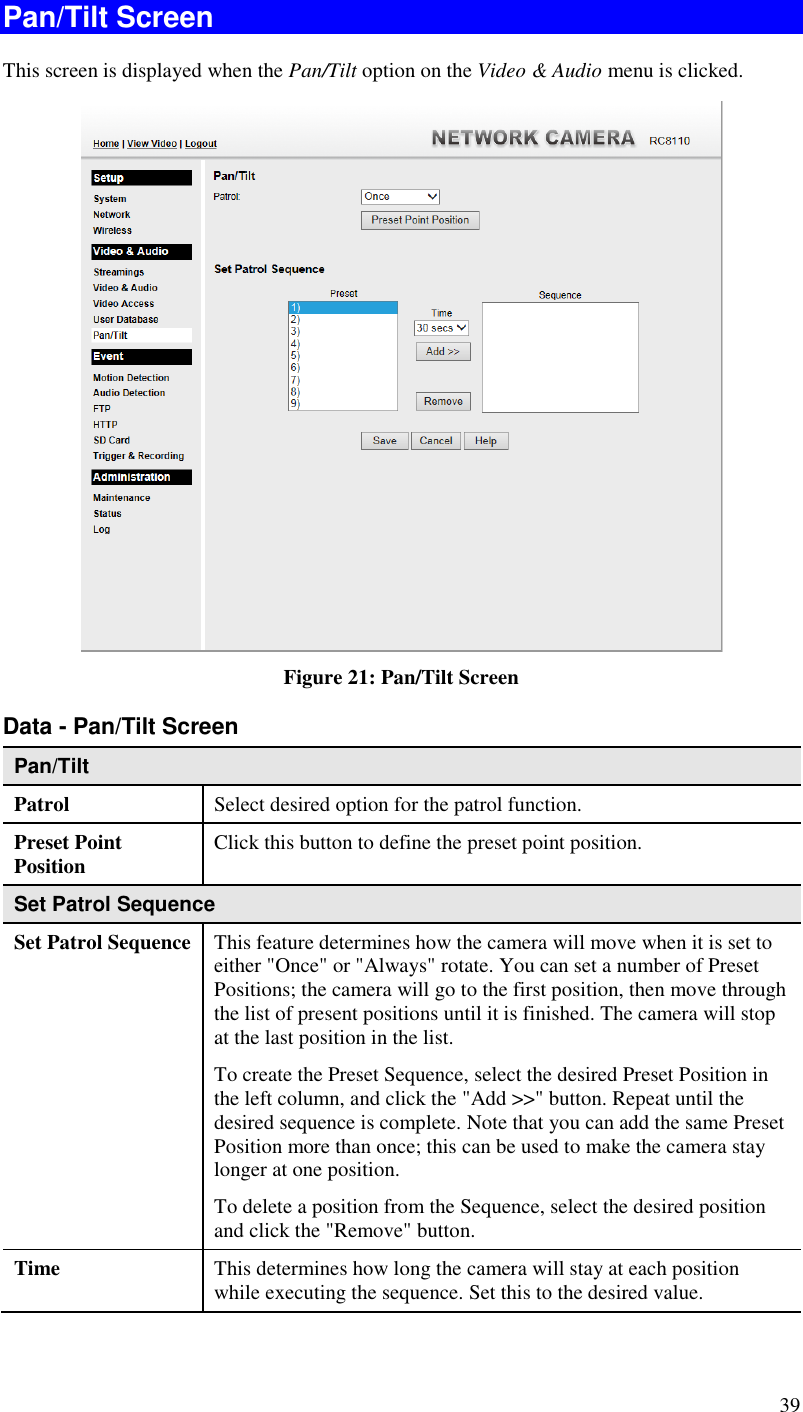
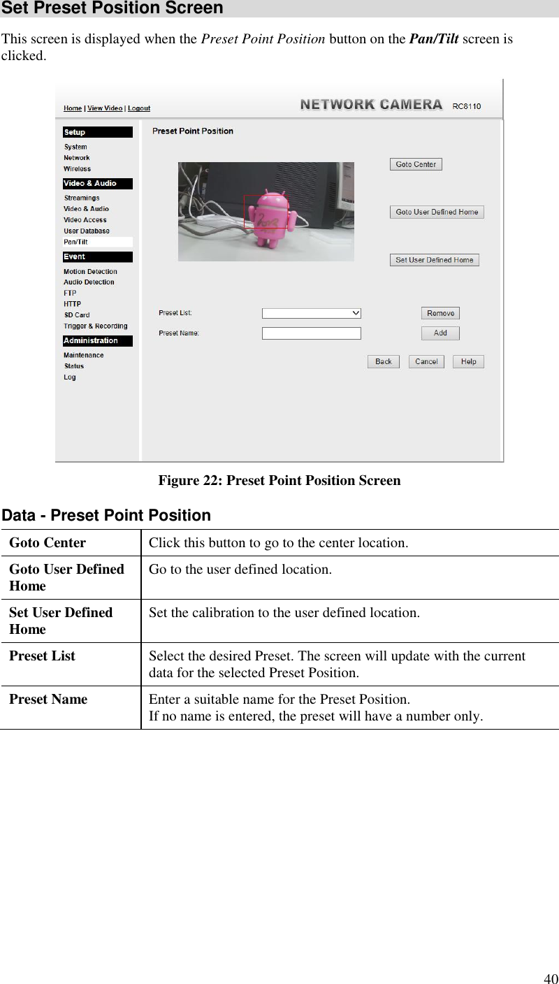
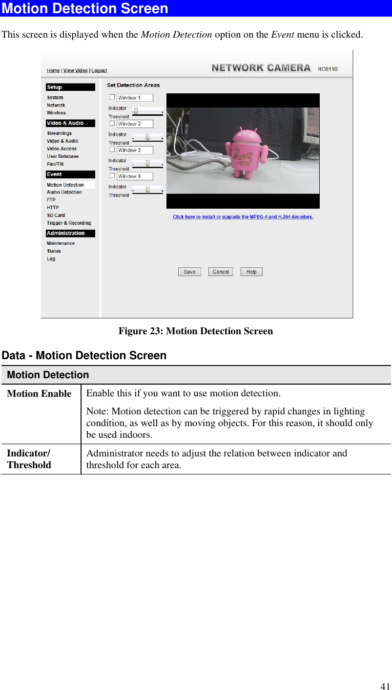
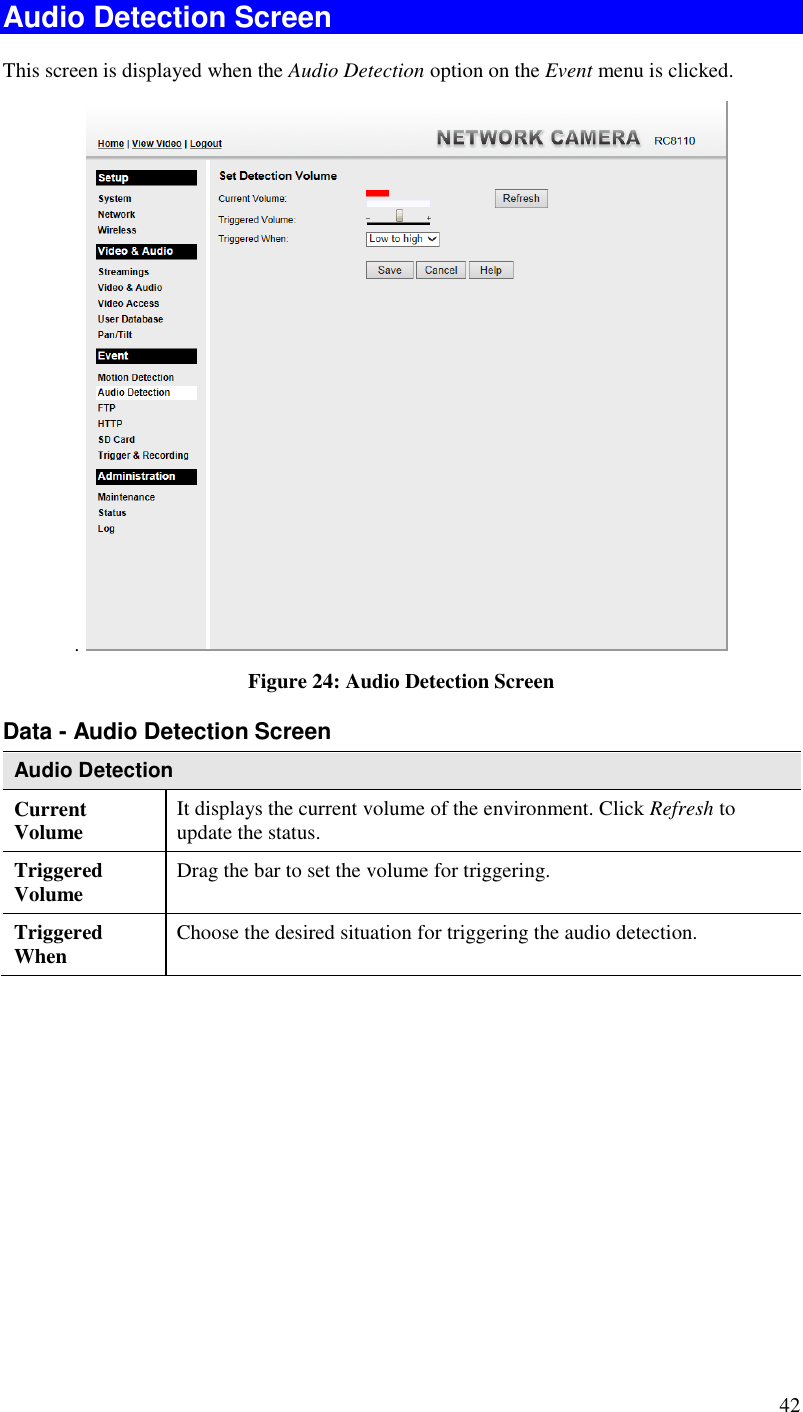
Sercomm RC8111 Wireless Network HD Camera User Manual Wireless 802 11g Network Camera

Sercomm Corporation Wireless Network HD Camera Wireless 802 11g Network Camera

User Manual

    Wireless Network HD Camera                  User’s Guide
  Table of Contents CHAPTER 1 INTRODUCTION.............................................................................................. 1 Overview ............................................................................................................................ 1 Physical Details - Wireless Network HD Camera ........................................................... 4 Package Contents .............................................................................................................. 6 CHAPTER 2 BASIC SETUP ................................................................................................... 7 System Requirements ........................................................................................................ 7 Installation - Wireless Network HD Camera .................................................................. 7 CHAPTER 3 VIEWING LIVE VIDEO .................................................................................. 9 Overview ............................................................................................................................ 9 Requirements ..................................................................................................................... 9 Connecting to a Camera on your LAN ............................................................................ 9 Connecting to a Camera via the Internet ...................................................................... 11 Viewing Live Video ......................................................................................................... 13 CHAPTER 4 ADVANCED VIEWING SETUP ................................................................... 15 Introduction ..................................................................................................................... 15 Adjusting the Video Image ............................................................................................. 15 Controlling User Access to the Video Stream ............................................................... 17 Making Video available from the Internet .................................................................... 18 Viewing Live Video via the Internet .............................................................................. 20 Motion Detection Alerts .................................................................................................. 21 CHAPTER 5 WEB-BASED MANAGEMENT .................................................................... 22 Introduction ..................................................................................................................... 22 Connecting to Wireless Network HD Camera .............................................................. 22 Welcome Screen ............................................................................................................... 23 Administration Menu ...................................................................................................... 24 System Screen .................................................................................................................. 25 Network Screen................................................................................................................ 27 Wireless Screen ................................................................................................................ 30 Streamings ........................................................................................................................ 32 Video & Audio Screen ..................................................................................................... 34 Video Access Screen ........................................................................................................ 36 User Database Screen ...................................................................................................... 38 Pan/Tilt Screen ................................................................................................................ 39 Motion Detection Screen ................................................................................................. 41 Audio Detection Screen ................................................................................................... 42 FTP Screen ....................................................................................................................... 43 HTTP Screen.................................................................................................................... 44 Trigger & Recording Screen .......................................................................................... 45 Maintenance Screen ........................................................................................................ 47 Status Screen .................................................................................................................... 49 Log Screen ........................................................................................................................ 51 CHAPTER 7 TROUBLESHOOTING .................................................................................. 52 Overview .......................................................................................................................... 52 Problems ........................................................................................................................... 52 APPENDIX A SPECIFICATIONS ........................................................................................ 54 Wireless Network HD Camera ..................................................... 錯誤! 尚未定義書籤。 Regulatory Approvals ..................................................................................................... 54 Copyright Notice .............................................................................................................. 56
               Copyright  2014. All Rights Reserved. Document Version: 1.0  All trademarks and trade names are the properties of their respective owners.
 1 Chapter 1 Introduction This Chapter provides details of the Wireless Network HD Camera's features, components and capabilities. Overview The Wireless Network HD Camera has an Integrated Microcomputer and a high quality Mega Pixel Omni Vision CMOS Sensor, enabling it to display high quality live streaming video over your wired LAN, the Internet, and for the Wireless Network HD Camera, an 802.11N Wireless LAN. Using enhanced H.264 technologies, the Wireless Network HD Camera is able to stream high quality video and audio directly to your PC. The high compression capabilities of H.264 reduce network bandwidth requirements to amazingly low levels. Furthermore, with the built-in infrared LED, the Wireless IP camera can provide illumination around 5 meters long under low light conditions in a simple, economical manner.   Figure 1: Wireless Network HD Camera Features  Standalone Design.  The Wireless Network HD Camera is a standalone system with built-in CPU and Video encoder. It requires only a power source and a connection to your LAN or Wireless LAN.  Dual Video Support. The Wireless Network HD Camera can support H.264 and MJEPG video for different image compression. 1
 2  Stream Live Video to Multiple Users.  The video encoder and HTTP server built into the camera generate a ready-to-view video stream. Just connect to the camera using your Web browser to view live video.   Suitable for Home, Business or Public Facilities.  Whether for Home, Business or Public Facility surveillance, or just for entertainment and fun, the Wireless Network HD Camera has the features you need.  Multi-Protocol Support.  Supporting TCP/IP networking, HTTP and other Internet related protocols, the Wireless Network HD Camera can be easily integrated into your existing network.   IR LED Support. Each Wireless Network HD Camera has one infrared LED. The LED can provide illumination around 5 meters long, that can help to output a better video quality while under low-light conditions such as indoors, on cloudy days, or in the morning or evening.   Motion Detection.  This feature can detect motion in the field of view. The Wireless Network HD Camera will compare consecutive frames to detect changes caused by the movement of large objects. This function only works indoors due to the sensitivity of the CMOS sensor. When motion is detection or some other action may be triggered.  Flexible Scheduling.  You can limit access to the video stream to specified times using a flexible scheduling system. The Motion Detection feature can also have its own schedule, so it is active only when required.  Syslog Support.  If you have a Syslog Server, the Wireless Network HD Camera can send its log data to your Syslog Server.  Audio Support.  You can listen as well as look! Audio is encoded with the video if desired. With built-in microphone, it is useful for bi-direction voice conversation.  Day/Night Switch. With the day/night switching feature, you are able to view and record better images even in the dark of night. Internet Features  User-definable HTTP/HTTPS port number.  This allows Internet Gateways to use "port mapping" so the Wireless Network HD Camera and a Web Server can share the same Internet IP address.  NTP (Network-Time-Protocol) Support.  NTP allows the Wireless Network HD Camera to calibrate its internal clock from an Internet Time-Server. This ensures that the time stamp on Video from the Wireless Network HD Camera will be correct. Security Features  User Authentication.  If desired, access to live video can be restricted to known users. Users will have to enter their username and password before being able to view the video stream.   Password-Protected Configuration.  Configuration data can be password protected, so that it only can be changed by the Wireless Network HD Camera Administrator.  Wireless Features   Supports 11n Wireless Stations.  The 802.11n standard provides for backward compatibility with the 802.11b standard, so 802.11n, 802.11b and 802.11g Wireless  stations can be used simultaneously.  Wired and Wireless Network Support. The Wireless Network HD Camera supports either wired or wireless transmission.
 3  WEP Support.  Full WEP support (64/128 Bit) on the Wireless interface is provided.  WPA/WPA2 Support.  The WPA Personal/WPA2 Personal standard is also supported, allowing advanced encryption of wireless data.  WPS Support. WPS (Wi-Fi Protected Setup) can simplify the process of connecting any device to the wireless network by using the push button configuration (PBC) on the Wireless Network HD Camera, or entering a PIN code if there's no button.
 4 Physical Details - Wireless Network HD Camera  Front - Wireless Network HD Camera  Figure 2: Front Panel 1. Light Sensor This is hardware sensor to detect LUX. 2. Lens No physical adjustment is required or possible for the lens, but you should ensure that the lens cover remain clean. The image quality is degraded if the lens cover is dirty or smudged. 3. infrared LED It is used to provide illumination for night time. 4. Microphone The built-in microphone is useful for bi-direction voice conversation.  Rear - Wireless Network HD Camera  Figure 3: Rear Panel
 5 1. LAN port Use the provided RJ-45 cable to connect your Wireless Network HD Camera to a 10/100BaseT hub or switch. Note:   Plugging in the LAN cable will disable the Wireless interface. Only 1 interface can be active at any time.  The RJ-45 cable should only be connected or disconnected when the camera is powered OFF. Attaching or detaching the RJ-45 cable while the camera is powered on does NOT switch the interface between wired and wireless. 2. DC Power Input Connect the supplied 12V power adapter here. Do not use other power adapters; doing so may damage the camera. 3. WPS Button  Push the WPS button on the device and on your other wireless device to perform WPS function that easily creates an encryption-secured wireless connection automatically.  WPS PBC Mode.  When pressed and released (less then 3 seconds), the Wireless Network HD Camera will be in the WPS PBC mode (Auto link mode).  WPS Pin Code Mode.  When pressed and held for over 3 seconds, the Wireless Network HD Camera will be in the WPS Pin Code mode. 4. Reset Button This button is recessed; you need a pin or paper clip can be used to depress it. It can be activated at any time the camera is in the "ready" mode.  Reset to manufacturer default valued and reboot. When pressed and held over 10 seconds, the settings of Network Camera will be set to their default values. 5. Power LED (Green) On - Power on. Off - No power. Blinking - The Power LED will blink during start up. This will take 55 to 57 seconds. 6. Network LED (Green, Amber) On (Green) - Network (Wireless or LAN) connection is available. Off - Wireless or LAN is not connected or camera is not sending/receiving data. Blinking (Green) - Data is being transmitted or received via the LAN or Wireless connection. On (Amber) - If the LED is on for 5 seconds and then off, the WPS function is failed. Blinking (Amber) - WPS function is being processed.
 6 Package Contents The following items should be included: If any of these items are damaged or missing, please contact your dealer immediately. 1. Wireless Network HD Camera x 1 2. Stand  x 1 3. DC power adapter  x 1
 7 Chapter 2 Basic Setup This Chapter provides details of installing and configuring the Wireless Network HD Camera. System Requirements  To use the wired LAN interface, a standard 10/100BaseT hub or switch and network cable is required.   To use the Wireless interface on the wireless model, other Wireless devices must be compliant with the IEEE802.11b, IEEE802.11g or IEEE 802.11n specifications. All Wireless stations must use compatible settings.  The default Wireless settings are: Mode: Infrastructure SSID: ANY  Wireless Security: Disabled Domain: USA Channel No.: Auto   Installation - Wireless Network HD Camera 1. Assemble the Camera Attach the Camera Stand to the camera. 2. Connect the RJ-45 Cable Connect the Wireless Network HD Camera to a 10/100BaseT hub or switch, using the supplied  RJ-45 cable.   For this Model, it will disable the Wireless Interface. The Wireless and LAN interfaces cannot be used simultaneously. Using the LAN interface is recommended for initial configuration. After the Wireless settings are correct, the Wireless interface can be used.  The first time you connect to the camera, you should connect the RJ-45 cable and configure the Wireless Network HD Camera with appropriate settings. Then you can unplug the RJ-45 cable and power off the camera. The Wireless Network HD Camera will be in wireless interface when you power on the camera again.  2
 8 3. Power Up Connect the supplied 12Vpower adapter to the Wireless Network HD Camera and power up. Use only the power adapter provided. Using a different one may cause hardware damage. 4. Check the LEDs  The Power LED will turn on briefly, then start blinking. It will blink during startup, which takes 55 to 57 seconds.  After startup is completed, the Power LED should remain ON.  The Network LED should be ON. For more information, refer to Physical Details - Wireless Network HD Camera in Chapter 1.
 9 Chapter 3 Viewing Live Video This Chapter provides basic information about viewing live video. Overview This Chapter has details of viewing live video using Internet Explorer. But many other powerful features and options are available:  The camera administrator can also adjust the Video Stream, and restrict access to the video stream to known users by requiring viewers to supply a username and password. See Chapter 4 - Advanced Viewing Setup for details.  To make Live Video from the camera available via the Internet, your Internet Gateway or Router must be configured correctly. See Making Video available from the Internet in Chapter 4 - Advanced Viewing Setup for details. Requirements To view the live video stream generated by the Wireless Network HD Camera, you need to meet the following requirements:  Windows XP, 32-bit Windows Vista/Windows 7.  Internet Explorer 7 or later, Firefox 3.0 or later. Connecting to a Camera on your LAN To establish a connection from your PC to the Wireless Network HD Camera: 1. Start Internet Explorer. 2. In the Address box, enter "HTTP://" and the IP Address of the Wireless Network HD Camera. 3. When you connect, the following screen will be displayed. 3
 10  Figure 4: Home Screen 4. Click View Video. 5. If the Administrator has restricted access to known users, you will then be prompted for a username and password.  Enter the name and password assigned to you by the Wireless Network HD Camera administrator. 6. The first time you connect to the camera, you will be prompted to install decoders. Choose "I accept the terms of the license agreement" and click "OK". 7. Video will start playing automatically. There may be a delay of a few seconds while the video stream is buffered.
 11 Connecting to a Camera via the Internet You can NOT connect to a camera via the Internet unless the camera Administrator has configured both the camera and the Internet Gateway/Router used by the camera. See Making Video available from the Internet in Chapter 4 - Advanced Viewing Setup for details of the required configuration. Also, you need a broadband Internet connection to view video effectively. Dial-up connections are NOT supported. To establish a connection from your PC to the Wireless Network HD Camera via the Internet: 1. Obtain the following information from the Administrator of the camera you wish to connect to:  Internet IP Address or Domain Name of the camera.  Port number for HTTP connections.  Login (username, password) if required. 2. Start Internet Explorer. 3. In the Address box, enter the following: HTTP://Internet_Address:port_number  Where Internet_Address is the Internet IP address or Domain Name of the camera, and port_number is the port number used for HTTP (Web) connections to the camera. Examples using an IP address:  HTTP://203.70.212.52:1024 Where the Internet IP address is 203.70.212.52 and the HTTP port number is 1024. 4. When you connect, the following screen will be displayed.  Figure 5: Home Screen
 12 5. Click View Video. 6. If the Administrator has restricted access to known users, you will then be prompted for a username and password.  Enter the name and password assigned to you by the Wireless Network HD Camera administrator. 7. The first time you connect to the camera, you will be prompted to install decoders. Choose "I accept the terms of the license agreement" and click "OK". 8. Video will start playing automatically. There may be a delay of a few seconds while the video stream is buffered.
 13 Viewing Live Video After installing the decoders, you will be able to view the live video stream in its own window, as shown below.  Figure 6: View Video Screen There are a number of options available on this screen, accessed by select list, button or icon. See the table below for details. Note: The options can only be configured while using IE browser. Other browsers can just view the video rather than configuration.  If the video still cannot be viewed, please install the decoders to solve this problem. You can install it from the following screens:  View Video Screen (preferred)  Figure 7: Install Decoders  Motion Detection Screen
 14 General Options These options are always available, regardless of the type of camera you are connected to.  Streaming.  Use this drop-down list to select the desired streaming.   Full Size. When using high-resolution mode (1280*720), click this button to see the full size of the image.  Select the desired option from the drop-down list.  Use this icon to start/stop viewing.  Use this icon to make the image back to original size.  Zoom Out.  A digital zoom out feature is available. To zoom out the window, click this icon.  Zoom In.  A digital zoom in feature is available. To zoom in the window, click this icon.   Speaker On/Off.  Use this button to turn the PC's speaker on or off.  Audio Upload On/Off.  Use this button to toggle the microphone on or off.  Volume.  If Speaker or Microphone is enabled, use this slider to adjust the volume.  Full Screen Display. Click this button to see the full screen of the image.  Camera Patrol.  Move through the Preset positions in the sequence defined by the Camera Administrator.  Camera Auto Pan. Click this to have the camera moved from left to right automatically.  Direct P/T. Use this to move the camera to the Pan/Tilt position directly.  Preset Points.  Select the desired Preset points.  Move Control.  Use this to move the camera to the desired position. There may a short delay after clicking the desired icon. You should wait a couple of seconds rather than click again. Or you can drag the vertical or horizontal slider bar to have quicker movement of the Network Camera to the desired position.
 15 Chapter 4 Advanced Viewing Setup This Chapter provides information about the optional settings and features for viewing video via the Wireless Network HD Camera. This Chapter is for the Camera Administrator only. Introduction This chapter describes some additional settings and options for viewing live Video:  Adjusting the video image  Controlling user access to the live video stream  Making video available from the Internet  Using the Motion Detection feature Adjusting the Video Image If necessary, the Wireless Network HD Camera Administrator can adjust the Video image.   To Adjust the Video Image: 1. Connect to the Web-based interface of the Wireless Network HD Camera. (See Chapter 5 - Web-based Management for details.) 2. Select Administration, then Streamings. You will see a screen like the example below.  Figure 8: Streamings Screen 3. Make the required adjustments, as explained below, and save your changes. 4
 16  Default Streaming Channel Select the default channel for streaming from the drop-down list. Streaming 1 Settings Video Format Select the desired format from the list. Resolution Select the desired video resolution format.   Video Quality Control  Constant Bit Rate: Select the desired bit rate. The default is set to 4.0 Mbps.  Fixed Quality: Select the desired option. The default fix quality is set to Normal. GOV Length Adjust the GOV interval in frame base. "2" means 1 I frame and 1 P Frame. "3" means 1 I frame and 2 P Frames. Enter the desired value between 2 and 150. Max. Frame Rate Select the desired Maximum frame rate for the video stream.  The default value is 30. User Defined URI You may enter the URI up to 32 characters long for accessing the live video from camera through cell phone connection. Streaming 2/3 Settings Enable Check the box if you want to enable the streaming. Video Format Select the desired format from the list. Resolution Select the desired video resolution format.   Video Quality Control  Constant Bit Rate: Select the desired bit rate. The default is set to 1.0 Mbps.  Fixed Quality: Select the desired option. The default fix quality is set to Normal. GOV Length Adjust the GOV interval in frame base. "2" means 1 I frame and 1 P Frame. "3" means 1 I frame and 2 P Frames. Enter the desired value between 2 and 150. Max. Frame Rate Select the desired Maximum frame rate for the video stream.  The default value is 30. User Defined URI You may enter the URI up to 32 characters long for accessing the live video from camera through cell phone connection.
 17 Controlling User Access to the Video Stream By default, anyone can connect to the Wireless Network HD Camera and view live Video at any time. If desired, you can limit access to scheduled times, and also restrict access to known users. To Control User Access to Live Video: 1. Connect to the Web-based interface of the Wireless Network HD Camera. (See Chapter 5 - Web-based Management for details.) 2. Select Administration, then Video Access.  3. Set the desired options for Access. Access Select the desired option as required:  If the User Access is enabled, users will be prompted for a username and password when they connect to the camera for viewing video.   When Video Access is enabled, viewing video is only available during the scheduled periods, and unavailable at other times. If this option is selected, you need to define a schedule; otherwise it is always disabled.  However, viewing video is still possible by logging in as the Administrator.   Figure 9: Controlling User Access See Chapter 5 - Web-based Management for further details about using the Video Access and User Database screens.
 18 Making Video available from the Internet If your LAN is connected to the Internet, typically by a Broadband Gateway/Router and Broadband modem, you can make the Wireless Network HD Camera available via the Internet. You will need to configure your Router or Gateway to allow connections from the Internet to the camera. Router/Gateway Setup Your Router or Gateway must be configured to pass incoming TCP (HTTP) connections (from Internet Viewers) to the Wireless Network HD Camera. The Router/Gateway uses the Port Number to determine which incoming connections are intended for the Wireless Network HD Camera. This feature is normally called Port Forwarding or Virtual Servers, and is illustrated below. The Port Forwarding/Virtual Server entry tells the Router/Gateway that incoming TCP connections on port 1024 should be passed to the Wireless Network HD Camera. If necessary, check the user manual for your Router/Gateway for further details.  Figure 10: Connecting via the Internet   The "Port" for the Port Forwarding / Virtual Server entry above is the " Secondary Port" number specified on the Network screen of the Wireless Network HD Camera.
 19 Wireless Network HD Camera Setup The Wireless Network HD Camera configuration does NOT have to be changed, unless:  You wish to change the port number from the default value. HTTPS Port Configuration Normally, HTTP (Web) connections use port 80. Since the Wireless Network HD Camera uses HTTP, but port 80 is likely to be used by a Web Server, you can use a different port for the Wireless Network HD Camera. This port is called the Secondary Port. The default HTTP/HTTPS Secondary Port is 1025. If you prefer to use a different port number, you can specify the port number on the Wireless Network HD Camera's Network screen, as shown below.  Figure 11: Network Screen See Chapter 5 - Web-based Management for further details on using the Network screen.   Viewers need to know this port number in order to connect and view live Video, so you must inform viewers of the correct port number.
 20 Viewing Live Video via the Internet Clients (viewers) will also need a broadband connection; dial-up connections are NOT recommended. Viewing Live Video Using your Web Browser If using your Web browser, you need to know the Internet IP address (or the Domain name) of the camera's Router/Gateway, and the correct port number. Enter the Internet address of the Router/Gateway, and its port number, in the Address (or Location) field of your Browser. Example - IP address:  HTTP://203.70.212.52:1024 Where the Router/Gateway's Internet IP address is 203.70.212.52 and the "Secondary Port" number on the Wireless Network HD Camera is 1024.
 21 Motion Detection Alerts The Motion Detection feature can generate an Alert when motion is detected. The Wireless Network HD Camera will compare consecutive frames to detect changes caused by the movement of large objects.  But the motion detector can also be triggered by:  Sudden changes in the level of available light  Movement of the camera itself. Try to avoid these situations. The motion detection feature works best in locations where there is good steady illumination, and the camera is mounted securely. It cannot be used outdoors due to the sensitivity of the CMOS sensor. Note: The Motion Detection settings can only be configured while using IE browser.  To Use Motion Detection Alerts Using the Web-based interface on the Wireless Network HD Camera, select the Motion Detection screen, then configure this screen as described below.  Figure 12: Motion Detection 1. Enable the Motion Detection feature. 2. Set the area or areas of the video image to be examined for movement. You can define up to 4 areas, and set the motion threshold individually for each area. 3. If using a schedule, define the desired schedule in Trigger & Recording screen. 4. Save your changes.  If the Motion Detection feature is enabled, but the related options in the Trigger & Recording screen are not enabled, then the only action when motion is detected is to log this event in the system log.
 22 Chapter 5 Web-based Management This Chapter provides Setup details of the Wireless Network HD Camera’s Web-based Interface. This Chapter is for the Camera Administrator only. Introduction The Wireless Network HD Camera can be configured using your Web Browser. The Wireless Network HD Camera must have an IP address which is compatible with your PC. Connecting to Wireless Network HD Camera  If using only your Web Browser, use the following procedure to establish a connection from your PC to the Wireless Network HD Camera:  Once connected, you can add the Wireless Network HD Camera to your Browser's Favorites or Bookmarks. Connecting using your Web Browser 1. Start your WEB browser. 2. In the Address box, enter "HTTP://" and the IP Address of the Wireless Network HD Camera.  3. You will then be prompted for a username and password.  If using the default values, enter administrator for the name, and leave the password blank.  Otherwise, enter the Administrator ID and Administrator Password set on the Maintenance screen.  5
 23 Welcome Screen When you connect, the following screen will be displayed.  Figure 13: Welcome Screen The menu options available from this screen are:  View Video - View live Video using your Web Browser. See Chapter 3 - Viewing Live Video for details.  Administration - Access the Administration menu.
 24 Administration Menu Clicking on Administration on the menu provides access to all the settings for the Wireless Network HD Camera. The Administration menu contains the following options: Setup  System   Network  Wireless   I/O Port Video & Audio  Streamings  Video & Audio   Video Access  User Database  Pan/Tilt  Event  Motion Detection  Audio Detection  FTP  HTTP  Trigger & Recording Administration   Maintenance  Status  Log
 25 System Screen After clicking Administration on the main menu, or selecting System on the Administration menu, you will see a screen like the example below.  Figure 14: System Screen Data - System Screen System Settings Device ID This displays the ID for the Wireless Network HD Camera. Camera Name Enter the desired name for the Wireless Network HD Camera. Description This field is used for entering a description, such as the location of the Wireless Network HD Camera. Date & Time  Date Format Select the desired date format, it will also be used to display the date and time as an overlay on the video image.  The abbreviations used to predefine the date formats are list as follows:   YYYY-MM-DD = Year-Month-Day, e.g. 2006-01-31   MM/DD/YYYY = Month/Day/Year, e.g. 01/31/2006  DD/MM/YYYY = Day/Month/Year, e.g. 31/01/2006 Current  Date & Time This displays the current date and time on the camera. If it's not correct, click the Change button to modify the date/time settings. This button will open a sub-screen where you have 2 options:  Set the camera's date and time to match your PC.  Enter the correct date and time.
 26 Time Zone Choose the Time Zone for your location from the drop-down list.  If your location is currently using Daylight Saving, please enable the Adjust for daylight saving checkbox. Network Time Protocol Enable or disable the Time Server feature as required. If Enabled, the Wireless Network HD Camera will contact a Network Time Server at regular intervals and update its internal timer. NTP Server Address Enter the address for the desired NTP server. Update The Schedule determines how often the Wireless Network HD Camera contacts the NTP Server.  Select the desired options. LED Operation Enable this if you want to use this function.
 27 Network Screen This screen is displayed when the Network option is clicked.  Figure 15: Network Screen  Data - Network Screen Network Internet Connection Type There are 3 connection types:  Obtain Address Automatically (DHCP): If selected, the Wireless Network HD Camera will obtain its IP address and related information from a DHCP Server. Only select this option if your LAN has a DHCP Server.  Static IP Address: If selected, you must assign the following data to the Wireless Network HD Camera.   IP Address - Enter an unused IP address from the address range used on your LAN.  Subnet Mask - Use the same value as PCs on your LAN.  Default Gateway - Use the same value as PCs on your LAN.   Obtain DNS server address automatically If selected, the Wireless Network HD Camera will use the DNS address or addresses provided by the DHPC server.  This option is only available if the IP address setting is Obtain an IP address Automatically.
 28 Use the following DNS server address Primary DNS server - Use the same value as PCs on your LAN. Normally, your ISP will provide this address.  Secondary DNS server - This is optional. If entered, this DNS will be used if the Primary DNS does not respond. HTTP/HTTPS This sets the port number for HTTP/HTTPS connections to the Camera, whether for administration or viewing video.  The HTTP (HyperText Transfer Protocol) is used for the standard of transferring files (text, graphic images and other multimedia files) on the World Wide Web. The default HTTP port is 60101. HTTPS (Hypertext Transfer Protocol Secure) can provide more secure communication with the SSL/TLS protocol, which support data encryption to HTTP clients and servers. The default HTTPS port is 1025. The Secondary port can be used for other service and when more than 2 cameras are in use. If enabled, you can connect using either port 80 or the Secondary port. You must enter the Secondary port number (between 1024 to 65535) in the field provided. Note that when using a port number which is not 80, you must specify the port number in the URL. For example, if the Camera's IP address was 192.168.1.100 and the Secondary port was 1024, you would specify the URL for the Camera as follows:       http://192.168.1.100:1024 RTP/RTSP The RTSP (Real Time Streaming Protocol), a standard for connected client(s) to control streaming data (MPEG-4) over the World Wide Web. Enter the RTSP Port number (between 1024 and 65535) in the field provided. The default RTSP Port is 554. The RTP (Real Time Transport Protocol), an Internet protocol for transmitting real-time data such as audio and video. Max RTP Data Packet field will let users limit the size of the file. Enter the desired value between 400 and 1400. Note: RTSP and RTP settings are for cell phone only. UPnP Enable Discovery If enabled, the Wireless Network HD Camera will broadcast its availability through UPnP. UPnP compatible systems such as Windows XP will then be able to detect the presence of the Wireless Network HD Camera. Enable Traversal If enabled, HTTP connections (from your Web Browser) can use secondary port instead of port 80 (the standard HTTP port) to access the camera.  Bonjour Enable Bonjour Service If enabled, the Wireless Network HD Camera can be accessed through a "Bonjour" enabled browser, such as Microsoft Internet Explorer (with a Bonjour plug-in) or Safari browser. You can also find other Bonjour-enabled devices on your network.
 29 QoS Enable QoS Mode If enabled, the throughput level (for Video and Audio) is guaranteed through QoS (Quality of Service). DSCP Enter the desired value of Differentiated Services Code Point (DSCP).  The value must be between 0 and 63.
 30 Wireless Screen  This screen is displayed when the Wireless menu option is clicked.  Figure 16: Wireless Screen Data - Wireless Screen Wireless Network  Site Survey Click the "Site Survey" button and select from a list of available APs. WSC PIN Code It displays the WSC PIN code number for the camera. SSID This must match the value used by other devices on your wireless LAN. The Default is ANY. Note! The SSID is case sensitive. Domain Select your region from the drop-down list. Channel No.  In Infrastructure mode, this setting is ignored. The Wireless Network HD Camera will use the Channel set on the Access Point.  For Ad-hoc mode, select the Channel you wish to use on your Wireless Network HD Camera. Other Wireless stations should use the same setting.  If you experience interference (shown by lost connections and/or slow data transfers) you may need to experiment with different channels to see which one is the best.
 31 Security Security System Select the desired option, and then enter the settings for the selected method:   Disabled - No security is used. Anyone using the correct SSID can connect to your network. This is default.  WEP - The 802.11b standard. Data is encrypted before transmission, but the encryption system is not very strong.   WPA/WPA2 Personal - Like WEP, data is encrypted before transmission. WPA is more secure than WEP, and should be used if possible. WPA Personal is the version of WPA which does NOT require a Radius Server on your LAN. WEP Authentication Type Normally this can be left at the default value of "Automatic." If that fails, select the appropriate value - "Open System" or "Shared Key." Check your wireless card's documentation to see what method to use. Note: In Infrastructure mode, either setting will normally work, since most Access Points can use both methods. WEP Encryption Select the WEP Encryption level:   64 Bit Keys (10 Hex chars)   128 Bit Keys  (26 Hex chars)  64 Bit Keys (5 ASCII chars)  128 Bit Keys  (13 ASCII chars) Passphrase Enter a word or group of printable characters in the Passphrase box and click the "Generate Key" button to automatically configure the WEP Key(s). If encryption strength is set to 64-bit, then each of the four key fields will be populated with key values. If encryption strength is set to 128-bit, then only the selected WEP key field will be given a key value. WEP Keys  Use the radio buttons to select the default key.   Enter the key value you wish to use. Other stations must have the same key values.   Keys must be entered in Hex. Hex characters are the digits (0 ~ 9) and the letters A ~ F.   Click Clear Keys to set the Keys to be blank.  Test Wireless Click this button to test the wireless connection. WPA/WPA2 Personal Shared Key Enter the key value. Data is encrypted using a key derived from the network key. Other Wireless Stations must use the same network key. The PSK must be from 8 to 63 characters or 64 hex characters in length.
 32 Streamings This screen is displayed when the Streamings menu option is clicked. If you want to view streaming via the cell phone: 1. Cell phone should be supported by 3GPP protocol. 2. Enter 554 for RTSP port number in the Network screen. 3. The H.264 format support cell phone option. 4. Enter the following address in the URI: RTSP:// Router IP address / User Defined URI 5. Select 15 fps for Max Frame Rate. Note! Due to the bandwidth limitation for the cell phone usage, please set the resolution, quality and frame rate to lower values.  Figure 17: Streamings Screen
 33 Data - Streamings Screen Default Streaming Channel Select the default channel for streaming from the drop-down list. Streaming 1 Settings Video Format Select the desired format from the list. Resolution Select the desired video resolution format.   Video Quality Control  Constant Bit Rate: Select the desired bit rate. The default is set to 2.0 Mbps.  Fixed Quality: Select the desired option. The default fix quality is set to Normal. Profile This is only for H.264 format only. There are 3 options:  Baseline Profile  Main Profile  High Profile GOV Length Adjust the GOV interval in frame base. "2" means 1 I frame and 1 P Frame. "3" means 1 I frame and 2 P Frames. Enter the desired value between 2 and 150. Max. Frame Rate Select the desired Maximum frame rate for the video stream.  The default value is 30. User Defined URI You may enter the URI up to 32 characters long for accessing the live video from camera through cell phone connection. Streaming 2/3 Settings Enable Check the box if you want to enable the streaming. Video Format Select the desired format from the list. Resolution Select the desired video resolution format.   Video Quality Control  Constant Bit Rate: Select the desired bit rate. The default is set to 1.0 Mbps.  Fixed Quality: Select the desired option. The default fix quality is set to Normal. Profile This is only for H.264 format only. There are 3 options:  Baseline Profile  Main Profile  High Profile GOV Length Adjust the GOV interval in frame base. "2" means 1 I frame and 1 P Frame. "3" means 1 I frame and 2 P Frames. Enter the desired value between 2 and 150. Max. Frame Rate Select the desired Maximum frame rate for the video stream.  The default value is 20. User Defined URI You may enter the URI up to 32 characters long for accessing the live video from camera through cell phone connection.
 34 Video & Audio Screen This screen is displayed when the Video & Audio menu option is clicked.  Figure 18: Video & Audio Screen Data - Video & Audio Screen Basic Video Adjustment Power Line Frequency Select the power line frequency (50Hz or 60Hz) used in your region, to improve the picture quality under florescent lighting. White Balance Select the desired option to match the current environment and lighting. Brightness If necessary, you can adjust the brightness to obtain a better image. For example, if the camera is facing a bright light, the image may be too dark. In this case, you can increase the brightness. Sharpness Select the desired option for the sharpness. You can select a Sharpness value between -3 and 3. Contrast Select the desired option for the Contrast. You can select a value between -3 and 3. Saturation Select the desired option for the Saturation. You can select a value between -3 and 3. Day/Night Switch Switching Method The Wireless Network HD Camera supports Day/Night mode switch for getting better quality of the low light condition. Select the desired method to use this function.
 35 IRLED Luminance Select the desired lightness for the IR LED. Options Enable Microphone Enable audio by checking this checkbox. Using Audio will increase the bandwidth requirements slightly. Audio Type Select the desired audio type. Flip This setting will have the image swapped top-to-bottom. Mirror This setting will have the image swapped left-to-right. Enable Time Stamp If enabled, the current time will be displayed on the Video image. Enable Text Display Enable this setting if you want text to be displayed on the Video image, and enter the desired text - up to 20 characters. This feature is often used to identify each camera when multiple cameras are installed.
 36 Video Access Screen This screen is displayed when the Video Access option is clicked.  Figure 19: Video Access Screen Data - Video Access Screen User Access Enable Security Checking  If disabled (default) - No login required. Users do not have to provide a username and password when they connect to the camera for viewing video.  If enabled - Require login. Users will be prompted for a username and password when they connect to the camera for viewing video. The camera administrator must use the "User Database" menu option to create the desired users. Video Access Enable Scheduled Video Access  If enabled - Viewing video is available during the scheduled periods and unavailable at other times. If this option is selected, you need to define a schedule. If no schedule is defined, this option is always disabled.   If disabled - The option will remain disabled until you enable it. Note that regardless of which setting is chosen, the Administrator can ALWAYS access the camera and view live video. Access Schedule Scheduled Periods  This displays all periods you have entered into the database. If you have not entered any periods, this list will be empty. Delete Use the Delete button to delete the selected item in the list.
 37 Add New Schedule Day Choose the desired option for the period. Start Time Enter the start time using a 24 hr clock. End Time Enter the end time using a 24 hr clock. Add Click this button to add a new period. Clear Use this button to clear the input fields.
 38 User Database Screen This screen is displayed when the User Database option is clicked.  Figure 20: User Database Screen Data - User Database Screen Existing Users User List This displays all users you have entered into the User database. If you have not entered any users, this list will be empty. The maximum number of users is 20. Edit, Delete, Delete All Use these buttons to manage the user database. User Properties User Name Enter the name for the user here.   Spaces, punctuation, and special characters must NOT be used in the name.   The name is case insensitive (case is ignored), so you can not have 2 names which differ only by case. User Password The password for this user. Confirm Password Re-enter the password for the user, to ensure it is correct. Control Level Select either Viewer or Operator for the user you plan to add.  Add Button Click this button to add a new user, using the data shown on screen. Clear Button Use this button to clear the input fields, ready to add a new user.
 39 Pan/Tilt Screen This screen is displayed when the Pan/Tilt option on the Video & Audio menu is clicked.  Figure 21: Pan/Tilt Screen Data - Pan/Tilt Screen Pan/Tilt Patrol Select desired option for the patrol function. Preset Point Position Click this button to define the preset point position. Set Patrol Sequence Set Patrol Sequence This feature determines how the camera will move when it is set to either "Once" or "Always" rotate. You can set a number of Preset Positions; the camera will go to the first position, then move through the list of present positions until it is finished. The camera will stop at the last position in the list.  To create the Preset Sequence, select the desired Preset Position in the left column, and click the "Add >>" button. Repeat until the desired sequence is complete. Note that you can add the same Preset Position more than once; this can be used to make the camera stay longer at one position.  To delete a position from the Sequence, select the desired position and click the "Remove" button. Time This determines how long the camera will stay at each position while executing the sequence. Set this to the desired value.
 40 Set Preset Position Screen This screen is displayed when the Preset Point Position button on the Pan/Tilt screen is clicked.   Figure 22: Preset Point Position Screen Data - Preset Point Position Goto Center Click this button to go to the center location. Goto User Defined Home Go to the user defined location. Set User Defined Home Set the calibration to the user defined location. Preset List Select the desired Preset. The screen will update with the current data for the selected Preset Position. Preset Name Enter a suitable name for the Preset Position. If no name is entered, the preset will have a number only.
 41 Motion Detection Screen This screen is displayed when the Motion Detection option on the Event menu is clicked.    Figure 23: Motion Detection Screen Data - Motion Detection Screen Motion Detection Motion Enable Enable this if you want to use motion detection.  Note: Motion detection can be triggered by rapid changes in lighting condition, as well as by moving objects. For this reason, it should only be used indoors. Indicator/ Threshold Administrator needs to adjust the relation between indicator and threshold for each area.
 42 Audio Detection Screen This screen is displayed when the Audio Detection option on the Event menu is clicked. .   Figure 24: Audio Detection Screen Data - Audio Detection Screen Audio Detection Current Volume It displays the current volume of the environment. Click Refresh to update the status. Triggered Volume Drag the bar to set the volume for triggering. Triggered When Choose the desired situation for triggering the audio detection.
 43 FTP Screen This screen is displayed when the FTP option on the Event menu is clicked.  Figure 25: FTP Screen Data - FTP Screen Primary/Secondary FTP FTP Server  Enter the address of the FTP Server. Port Enter the Port of the FTP Server to be connected. Login name Enter your login name for the FTP Server. Password Enter your password for the FTP Server. Enable Passive Mode Check the box to enable the Passive mode feature of the FTP. File Path Name Enter the file path/name of the FTP. Test the Server Click this button to test the server connection.  Secondary FTP Check the box to upload to the Secondary FTP if the camera can not connect to the primary FTP.
 44 HTTP Screen This screen is displayed when the HTTP option on the Event menu is clicked.  Figure 26: HTTP Screen Data - HTTP Screen HTTP Notification URL Enter the URL of your HTTP notification server. User Name Enter the user name of your HTTP server. Password Enter the password to match the user name above. Proxy Server Name Specify the proxy server name in the provided field if the camera needs to pass through a Proxy Server to do the HTTP notification. Proxy User Name Enter the user name for the proxy server. Proxy Password Enter the password for the proxy server. Proxy Port Number Enter the port number for the proxy server. Method Select the desired method of form data encoding.   Get - It should be used if and only if the form processing is independent, which typically means a pure query form. Generally it is advisable to do so.   Post - If there are problems related to long URLs and non-ASCII character repertoires, which can make it necessary to use "POST" even for independent processing.
 45 Trigger & Recording Screen This screen is displayed when the Trigger & Recording option is clicked.  Figure 27: Trigger & Recording Screen Data - Trigger & Recording Screen Event Schedule Schedule List  The Event Schedule shows all of the event types currently configured in the Waterproof HD IP Camera, along with various information about their configuration, as listed below:   Name - the descriptive event name set by the user.  Enable - shows the event is enable or disable.  Trigger - shows what kind trigger activate the event.  Actions - shows what kind of the actions will be issued when the event is triggered. Add, Edit, Delete Use these buttons to manage the schedule list.
 46 Add a new Schedule  Figure 28: Add schedule screen  Name Enter the name of the schedule. Schedule Schedule Choose the desired option:  Always  Schedule  Never Trigger Event Trigger by  Motion Detection - Movement in a motion detection window can be used to trigger events.  Audio Detection - The sound detection can be used to trigger events.  HTTP Trigger- If checked, a HTTP CGI command will be delivered to the HTTP server.  Periodically - If checked, the events will be triggered at regular intervals of time.  Continuously - If checked, the events will be triggered continuously. Interval - Select the desired interval from the list. Actions  HTTP - If checked, a HTTP CGI command will be delivered to the HTTP server.  FTP - If checked, an FTP upload will be activated to the FTP server. (FTP servers must be configured on the FTP page.)  Attachment Type  Pre/Post Capture - Select the desired length. The size of the file depends on this setting, and also the Video size and degree of compression.
 47 Maintenance Screen .  Figure 29: Maintenance Screen Data - Maintenance Screen Administrator Login Administrator ID Enter the name for the Administrator here.  Spaces, punctuation, and special characters must NOT be used in the name.  Administrator Password The password for the Administrator. Verify Password Re-enter the password for the Administrator, to ensure it is correct. Firmware Upgrade Upgrade File Click the "Browse" button and browse to the location on your PC where you stored the Firmware file. Select this file. Start Click this button to start the Firmware. When the upgrade is finished, the Wireless Network HD Camera will restart, and this management connection will be unavailable during the restart. Clear File Name This does NOT stop the Upgrade process if it has started. It only clears the input for the "Upgrade File" field.
 48 Backup & Restore Backup Configuration File Click Backup button to save the current configuration information to a text file. It is suggested to backup the configuration file, in order to restore the camera easily. Restore Configuration File Click Restore button to reinitialize the camera to load the new updated software. Do this after loading the upgrade file. Clear File Name This does NOT stop the Restore process if it has started. It only clears the input for the "Restore Configuration File" field. Restore Factory Defaults  Click Defaults button to reloads all default settings on the camera. Restart Camera Click Restart button to restarts the camera.
 49 Status Screen .   Figure 30: Status Screen Data - Status Screen System Device Name This shows the name of the Wireless Network HD Camera. Description This shows the description of the Wireless Network HD Camera, such as location. F/W version The version of the current firmware installed.  Network MAC Address The current IP address of the Wireless Network HD Camera. Streaming (1~3) Video Format It displays the current format of video. Resolution The image size of the video stream. Video Quality This displays the image quality of the video stream. Frame Rate This displays the frame rate of the video stream.
 50 UPnP Traversal Status The current status of port mapping. Buttons Refresh Update the log and any other data on screen.
 51 Log Screen This screen displays a log of system activity. .   Figure 31: Log Screen Data - Log Screen Log System Log This is a log of system activity. Refresh Button Click this to update the data shown on screen. Clear Log Click this button to restart the log. Enable Syslog Service Check the box to enable the System Log Server feature. Syslog Server Address Enter the address of the Syslog Server.
 52 Chapter 7 Troubleshooting This chapter covers the most likely problems and their solutions. Overview This chapter covers some common problems that may be encountered while using the Wireless Network HD Camera and some possible solutions to them. If you follow the suggested steps and the Wireless Network HD Camera still does not function properly, contact your dealer for further advice. Problems Problem 1: I can't connect to the Wireless Network HD Camera with my Web Browser to configure it. Solution 1: It is possible that your PC's IP address is not compatible with the IP address of the Wireless Network HD Camera.   Problem 2 When I try to connect to the Wireless Network HD Camera, I get prompted for a user name and password. Solution 2 You SHOULD be prompted for a user name and password if trying to access the Administration menu.  Enter the Administrator ID and Administrator Password set on the Maintenance screen. If you are just trying to view Video, the User Name/Password prompt indicates that the Administrator has restricted access to specified users. Ask the Administrator for your User Name and Password. Problem 3 I can't connect to the Wireless Network HD Camera using a Wireless connection. Solution 3 1) If a LAN cable is connected to the LAN port, the Wireless interface is disabled. Only one interface can be active. 2) Check that your PC and the Wireless Network HD Camera have compatible Wireless settings.  Mode (Infrastructure or Ad-hoc) must be correct.  ESSID must match.  WEP settings must match.  In Ad-hoc mode, the Channel should match, although this is often not required. Problem 4 Video quality may suddenly deteriorate. 7
 53 Solution 4 This can happen when an additional viewer connects to the Wireless Network HD Camera, overloading the camera or the available bandwidth. The image size and quality can be adjusted to cater for the required number of viewers and the available bandwidth. Problem 5 The motion detection feature doesn't send me any E-mail. Solution 5 It may be that the SMTP (Simple Mail Transport Protocol) server used by the camera to send the E-Mail will not accept mail. (This is to prevent span being sent from the server.). Try using a different SMTP server, or contact your ISP to see if SMTP access is being blocked. Problem 6 Using the motion detection feature, I receive E-Mails which don't show any moving objects. Solution 6 The motion detection feature doesn't actually detect motion. It compares frames to see if they are different. Major differences between frames are assumed to be caused by moving objects.  But the motion detector can also be triggered by:  Sudden changes in the level of available light  Movement of the camera itself. Try to avoid these situations. The motion detection feature works best in locations where there is good steady illumination, and the camera is mounted securely. This feature can NOT be used if the camera is outdoors. Problem 7 The image is blurry.  Solution 7 Try cleaning the lens, or adjusting the Video Quality Control setting on the Streamings screen. Video created by the lower settings will contain less detail; this is the trade-off for using less bandwidth. Problem 8 When is the best time to press WPS button? Solution 8 If there is no cable connected, you can press the WPS button after the Power LED starts blinking. Problem 9 In some older Window XP systems, it may not be able to see H.264 video streaming. Solution 9 In order to view H.264 video streaming in the older Window XP systems, please install the Microsoft .net framework 2.0 or later version, so the system will be able to deploy the built-in H.264 decoder of the camera. Problem 10 I use the camera via IE browser in protected mode of Windows Vista/7, there is no local recording/setup feature to be used. Even if I run it with IE browser in non-protected mode of Windows 7, the folder like "Windows" still can not be accessed. (There is no recording files found in this folder as well) Solution 10 There will be no local recording files and the setup service of associated folder if the IE browser is in protected mode. To use the local recording feature, please operate IE browser in  non-protected mode. Note! Some folders (ex. ″Windows″ folder) with high integrity level can not be accessed via non-protected mode of IE in Window 7.
 54 Appendix A Specifications Wireless Network HD Camera Model Wireless Network  HD Camera Dimensions 120mm (W) x 71mm (H) x 79mm (D) Operating Temperature 0 C to 45 C Video compression H.264 and MJPEG Image resolution 1280x 720, 640x480, 320x 240 (QVGA) Storage Temperature -20 C to 70 C Network Protocols TCP/IP,  DHCP, NTP, DNS, FTP, HTTP, HTTPS, RTSP, RTCP, UPnP  Network Interface 1 RJ-45 LAN connection for Ethernet  Wireless interface  IEEE 802.11n/802.11b/802.11g compatible, WEP 64/128 bit, WPA/WPA2 personal security support LEDs 1 Power Adapter 12V/1A, 100~240 VAC  Regulatory Approvals  FCC Statement This equipment has been tested and found to comply with the limits for a Class B digital device, pursuant to Part 15 of the FCC Rules.  These limits are designed to provide reasonable protection against harmful interference in a residential installation.  This equipment generates, uses and can radiate radio frequency energy and, if not installed and used in accordance with the instructions, may cause harmful interference to radio communications. However, there is no guarantee that interference will not occur in a particular installation. If this equipment does cause harmful interference to radio or television reception, which can be determined by turning the equipment off and on, the user is encouraged to try to correct the interference by one of the following measures:  Reorient or relocate the receiving antenna.  Increase the separation between the equipment and receiver.  Connect the equipment into an outlet on a circuit different from that to which the receiver is connected.  Consult the dealer or an experienced radio/TV technician for help. A
 55 To assure continued compliance, any changes or modifications not expressly approved by the party responsible for compliance could void the user's authority to operate this equipment. (Example - use only shielded interface cables when connecting to computer or peripheral devices). FCC Radiation Exposure Statement This equipment complies with FCC RF radiation exposure limits set forth for an uncontrolled environment. This equipment should be installed and operated with a minimum distance of 20 centimeters between the radiator and your body. This device complies with Part 15 of the FCC Rules. Operation is subject to the following two conditions:  (1) This device may not cause harmful interference, and  (2) This device must accept any interference received, including interference that may cause undesired operation. This transmitter must not be co-located or operating in conjunction with any other antenna or transmitter.  Replaceable Batteries CAUTION RISK OF EXPLOSION  IF BATTERY IS REPLACED BY AN INCORRECT TYPE. DISPOSE OF USED BATTERIES ACCORDING  TO THE INSTRUCTIONS CE Approvals The Wireless Network HD Camera and the Ethernet Wireless Network HD Camera meet the guidelines of the European Union and comply with the 99/5/EEC and RTTE 99/5EG directives, including the following standards:  EN60950   EN300 328  EN301 489-1  EN301 489-17 This is a Class B product. In a domestic environment this product may cause radio interference in which case the user may be required to take adequate measures.
 56 Copyright Notice Many software components are covered by the GNU GPL (General Public License). Some are covered by other Licenses.  You can check more details of each applicable license by clicking the License button in the Maintenance screen.

Navigation menu